


-2-
v7.1
Meshlium
X
treme
Index
Document version: v7.1 - 03/2017
© Libelium Comunicaciones Distribuidas S.L.
INDEX
1. General and safety information ......................................................................................................... 6
2. Important: read me before using ....................................................................................................... 7
3. Meshlium v4.0 vs Meshlium v3.5 ....................................................................................................... 8
3.1. Capabilities comparison ............................................................................................................................................................8
3.2. Compatibility with Waspmote and Plug & Sense! nodes ..............................................................................................9
3.3. Compatibility with current cloud software ........................................................................................................................9
3.4. XBee-PRO 868 vs XBee 868LP ............................................................................................................................................... 10
3.5. XBee-PRO 900 vs XBee-PRO 900HP .................................................................................................................................... 11
3.6. 3G (SIM5215) vs 4G (LE910) ................................................................................................................................................... 11
4. Contents of the box ........................................................................................................................... 13
5. Specications ..................................................................................................................................... 15
6. How to use Meshlium ........................................................................................................................ 18
6.1. Power supply ..............................................................................................................................................................................18
6.2. External SIM socket .................................................................................................................................................................. 19
6.3. How to install the antennas ..................................................................................................................................................20
6.4. Installation of the IP65 Ethernet cable .............................................................................................................................. 21
6.5. Installing Meshlium .................................................................................................................................................................. 24
6.6. Initialization, restart and shutdown ................................................................................................................................... 24
6.7. Setting the time ......................................................................................................................................................................... 25
7. Understanding Meshlium ................................................................................................................. 26
7.1. Concepts ......................................................................................................................................................................................26
7.2. Meshlium models .....................................................................................................................................................................26
7.3. Storage .......................................................................................................................................................................................... 27
7.4. Application model by model ................................................................................................................................................ 27
8. Accessing Meshlium – make it easy!................................................................................................. 29
9. Network interfaces setup .................................................................................................................. 31
9.1. Ethernet setup............................................................................................................................................................................31
9.2. WiFi Access Point setup ...........................................................................................................................................................34
9.2.1. Conguration ...............................................................................................................................................................34
9.2.2. Clients connected ......................................................................................................................................................36

-3-
v7.1
Meshlium
X
treme
Index
9.3. Network setup conrmation .................................................................................................................................................37
9.4. 4G setup ....................................................................................................................................................................................... 38
9.5. Proxy setup .................................................................................................................................................................................. 39
10. Wireless Sensor Networks ............................................................................................................... 41
10.1. Meshlium and Waspmote ....................................................................................................................................................41
10.2. Receiving and storing data ................................................................................................................................................. 42
10.2.1. Receiving trough RF communications .............................................................................................................42
10.2.2. Receiving trough 4G / WiFi / Ethernet (HTTP) ...............................................................................................49
10.3. Capturer ..................................................................................................................................................................................... 49
10.3.1. Local database ..........................................................................................................................................................51
10.3.2. External Database ....................................................................................................................................................52
10.3.3. Show me Now ...........................................................................................................................................................55
10.3.4. Advanced database options ................................................................................................................................55
10.4. Logs .............................................................................................................................................................................................57
10.5. Sensor list .................................................................................................................................................................................. 58
10.6. OTA via FTP ...............................................................................................................................................................................59
11. Meshlium Visualizer ........................................................................................................................ 61
11.1. Working with the Visualizer ................................................................................................................................................ 61
12. Cloud Connectors ............................................................................................................................ 64
12.1. IoT platforms ............................................................................................................................................................................66
12.1.1. Amazon IoT ................................................................................................................................................................66
12.1.2. Esri .................................................................................................................................................................................71
12.1.3. IBM Bluemix ...............................................................................................................................................................75
12.1.4. IoT-Ticket .....................................................................................................................................................................76
12.1.5. Microsoft Azure Event Hubs ................................................................................................................................81
12.1.6. Microsoft Azure IoT Hub ........................................................................................................................................87
12.1.7. MQTT ............................................................................................................................................................................90
12.1.8. RIOT Platform ............................................................................................................................................................93
12.1.9. SensorUp IoT Platform ...........................................................................................................................................94
12.1.10. TechEdge SAP HANA ............................................................................................................................................95
12.1.11. Telefónica IoT Platform ........................................................................................................................................97
12.1.12. Telit .............................................................................................................................................................................98
12.1.13. ThingWorx ............................................................................................................................................................. 102
12.2. IoT Solutions ...........................................................................................................................................................................106
12.2.1. Amplía’s OpenGate ............................................................................................................................................... 106
12.2.2. BaseN .........................................................................................................................................................................107
12.2.3. B-Scada ..................................................................................................................................................................... 109
12.2.4. Cumulocity .............................................................................................................................................................. 111
12.2.5. DeviceLynk .............................................................................................................................................................. 112
12.2.6. Devicify ..................................................................................................................................................................... 114
12.2.7. eagle.io ..................................................................................................................................................................... 116

-4-
v7.1
Meshlium
X
treme
12.2.8. ElementBlue – RightSensor ...............................................................................................................................117
12.2.9. Ensura .......................................................................................................................................................................118
12.2.10. Extunda .................................................................................................................................................................. 120
12.2.11. IoTSens ...................................................................................................................................................................121
12.2.12. Kii ..............................................................................................................................................................................122
12.2.13. Nexmachina .........................................................................................................................................................124
12.2.14. Orchestra ............................................................................................................................................................... 126
12.2.15. Sentilo.....................................................................................................................................................................129
12.2.16. Simfony .................................................................................................................................................................. 130
12.2.17. SmartCityPlatform .............................................................................................................................................133
12.2.18. SmartPlants .......................................................................................................................................................... 135
12.2.19. Soa2 ...................................................................................................................................................................... 136
12.2.20. ThingPlus ............................................................................................................................................................... 142
13. Smartphone detection .................................................................................................................. 145
13.1. Devices detected ..................................................................................................................................................................147
13.2. WiFi Scanner ...........................................................................................................................................................................152
13.2.1. Concepts .................................................................................................................................................................. 152
13.2.2. Local database ....................................................................................................................................................... 155
13.2.3. External database ................................................................................................................................................. 156
13.3. Bluetooth Scanner ...............................................................................................................................................................158
13.3.1. Concepts .................................................................................................................................................................. 158
13.3.2. Local database ....................................................................................................................................................... 160
13.3.3. External database ................................................................................................................................................. 161
14. Tools ................................................................................................................................................ 163
14.1. Fresnel calculator ..................................................................................................................................................................163
14.2. Iperf ...........................................................................................................................................................................................163
14.3. Ping ............................................................................................................................................................................................164
14.4. Traceroute................................................................................................................................................................................165
14.5. Netstat ......................................................................................................................................................................................165
14.6. GPS .............................................................................................................................................................................................166
14.6.1. Concepts .................................................................................................................................................................. 166
14.6.2. Conguring GPS service .....................................................................................................................................166
14.6.3. Local database ....................................................................................................................................................... 168
14.6.4. External database ................................................................................................................................................. 169
14.7. Beep ...........................................................................................................................................................................................170
15. Database management ................................................................................................................. 171
15.1. Direct access ...........................................................................................................................................................................171
15.2. PhpMyAdmin .........................................................................................................................................................................171
Index

-5-
v7.1
Meshlium
X
treme
16. System Information ....................................................................................................................... 173
16.1. Hostname ................................................................................................................................................................................173
16.2. Password management ......................................................................................................................................................173
16.3. Disk usage ...............................................................................................................................................................................174
16.4. Internal temperature sensor .............................................................................................................................................174
16.5. Time synchronization ..........................................................................................................................................................175
17. Upgrading Meshlium .................................................................................................................... 176
17.1. Checking for updates ..........................................................................................................................................................176
17.2. Local le ...................................................................................................................................................................................177
17.3. URL .............................................................................................................................................................................................178
18. Rescue System ...............................................................................................................................179
18.1. Rescue steps ...........................................................................................................................................................................179
19. Expansion port .............................................................................................................................. 181
20. Manager System changelog ......................................................................................................... 182
21. Documentation changelog ........................................................................................................... 183
22. Certications .................................................................................................................................. 184
22.1. General overview ..................................................................................................................................................................184
22.2. CE (Europe) .............................................................................................................................................................................184
22.3. FCC (USA) .................................................................................................................................................................................185
22.4. IC (Canada) ..............................................................................................................................................................................186
22.5. ANATEL (Brazil) ......................................................................................................................................................................186
22.6. RCM (Australia) ......................................................................................................................................................................186
23. Maintenance .................................................................................................................................. 187
24. Disposal and recycling .................................................................................................................. 188
Index

-6-
v7.1
General and safety information
Meshlium
X
treme
1. General and safety information
IMPORTANT:
• All Documents and any examples they contain are provided as-is and are subject to change without notice. Except to the
extent prohibited by law, LIBELIUM makes no express or implied representation or warranty of any kind with regard to the
Documents, and specically disclaims the implied warranties and conditions of merchantability and tness for a particular
purpose.
• The information on LIBELIUM´s Websites has been included in good faith for general informational purposes only. It should
not be relied upon for any specic purpose and no representation or warranty is given as to its accuracy or completeness.
Read carefully the Limited Warranty and Terms and Conditions of Use before using “Meshlium”.
• Read carefully the “General Conditions of Sale and Use of Libelium”. This document can be found at
http://www.libelium.com/development/meshlium/technical_service
As specied in the Warranty document which you can nd at
http://www.libelium.com/development/meshlium/documentation, the client has 7 days from the day the order is
received to detect any failure and report that to Libelium. Any other failure reported after these 7 days may not be
considered under warranty.
• Do NOT open the enclosure. If you do so, you will lose the guarantee.
• Do not remove any of the components.
• Do not allow contact between metallic objects and the electronic part to avoid injury and burns.
• NEVER immerse the equipment in any liquid.
• Keep the equipment in a dry place away from any liquids that could spill.
• Check from the label that comes with the equipment the maximum permitted voltage and amperage range.
• Keep the equipment within the temperature range indicated in the specications section.
• Do not connect or power the equipment using cables that have been damaged.
• Place the equipment in an area to which only maintenance personnel can have access (in a restricted access zone).
• In any case, keep children away from the machine.
• If there is a power failure, immediately disconnect from the mains electricity.
• If using the car lighter as a power source, make sure that you follow the voltage and current specications indicated in the
section “How to use Meshlium”.
• If a software failure occurs, consult the section web support.
• Do not place the equipment on trees or plants as they could be damaged by its weight.
• Be particularly careful if you are connected through Ethernet or WiFi; if the settings are incorrectly altered, Meshlium could
become inaccessible.

-7-
v7.1
Important: read me before using
Meshlium
X
treme
2. Important: read me before using
The following list shows just some of the actions that produce the most common failures and warranty-voiding. Complete
documentation about usage can be found at:
http://www.libelium.com/development/meshlium/technical_service
Failure to comply with the recommendations of use will entail the guarantee cancellation.
• Do not interrupt the power supply before shutting down Meshlium properly through the “Shutdown” or “Restart” buttons
in the Manager System.
• Do not open the Meshlium enclosure in any case. This will automatically make the warranty void.
• Do not submerge Meshlium in liquids.
• Do not place Meshlium on places or equipment where the device could be exposed to shocks and/or vibrations.
• Do not expose Meshlium to temperatures below -20º C or above 50º C.
• Meshlium’s microprocessor must not overpass 75 Celsius degrees. The user must ensure that this temperature never
overpass. Especially when using WiFi Scan.
• Do not power Meshlium with other power sources than the original provided by Libelium.
For more information: http://www.libelium.com/meshlium
-8-
v7.1
Meshlium v4.0 vs Meshlium v3.5
Meshlium
X
treme
3. Meshlium v4.0 vs Meshlium v3.5
This evolution of Meshlium includes an important upgrade of the hardware capabilities. The most important changes are:
• Big step forward in performance, CPU performance 10 times better and RAM capacity 8 times bigger.
• Cellular connection upgraded to 4G for a very fast Internet connection and data synchronization.
• WiFi AP upgraded to WiFi b/g/n (up to 144 Mbps).
• New models of radio module for the 868 MHz and 900 MHz bands.
• Up to two RF (XBee) modules can be installed in the device, working with the 4G radio at the same time (2.4 GHz and
868/900 MHz).
• GPS/GLONASS capabilities for a faster global location.
• New improved design.
• Operating system updated including new versions of programs and system.
• New expansion port for future use of external I2C, USB or UART devices.
• New Meshlium is Microsoft Azure Certied (More info: https://azure.microsoft.com/es-es/marketplace/programs/certied/).
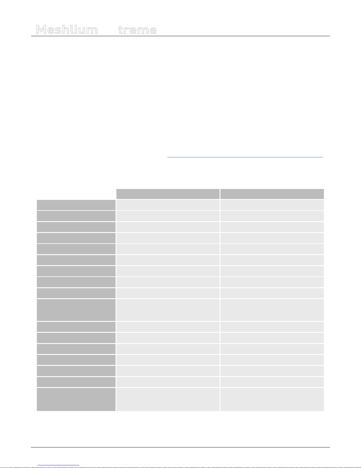
3.1. Capabilities comparison
Previous Meshlium version New Meshlium
CPU cores 1 4
CPU architecture 32 bits 64 bits
CPU frequency 500 MHz 1 GHz
RAM 256 MB DDR 2 GB DDR3
Storing Compact Flash 8 GB SSD disk 16 GB
Linux Kernel 2.6 3.16
Simultaneous cloud services 2-4 15-20
Boot time ~2 minutes Less than 1 minute
WiFi a/b/g (up to 54 Mbps) a/b/g/n (up to 144 Mbps)
Cellular
Up to 7.2 Mbps downlink (SIM5218)
Up to 384 kbps downlink (SIM5215)
Up to 42 Mbps downlink
Antenna connectors 4 10
RF module sockets 1 2
Geolocation GPS GPS + GLONASS
Root access Yes No
Power consumption ~10 W ~15 W (depending on number of radios)
Enclosure (mm) 210 x 190 x 60 30 x 220 x 80
Certications CE / FCC / IC
CE (Europe) / FCC (US) / IC (Canada) /
ANATEL (Brazil) / RCM (Australia) / PTCRB
(US) / AT&T (US)

-9-
v7.1
Meshlium v4.0 vs Meshlium v3.5
Meshlium
X
treme
3.2. Compatibility with Waspmote and Plug & Sense! nodes
Old hardware Compatible Notes
Plug & Sense! (Waspmote v1.2) 802.15.4 YES
Plug & Sense! (Waspmote v1.2) ZigBee NO Old ZigBee modules are EoL
Plug & Sense! (Waspmote v1.2) DigiMesh NO
Plug & Sense! (Waspmote v1.2) 900 NO
Old 900 MHz modules are EoL. Substituted by the
new 900HP radios.
Plug & Sense! (Waspmote v1.2) 868 NO
Old 868 MHz modules are EoL. Substituted by the
new 868 radios.
Plug & Sense! (Waspmote v1.2) WiFi YES
Plug & Sense! (Waspmote v1.2) 3G YES
Plug & Sense! (Waspmote v1.5) 802.15.4 YES
Plug & Sense! (Waspmote v1.5) 900 YES
Plug & Sense! (Waspmote v1.5) 868 YES
Plug & Sense! (Waspmote v1.5) WiFi YES
Plug & Sense! (Waspmote v1.5) 4G YES
Plug & Sense! (Waspmote v1.5) ZigBee NO Meshlium does not support this RF module
3.3. Compatibility with current cloud software
Cloud software Compatible Notes
Amazon IoT yes
Esri yes Only ArcGIS online
IBM Bluemix yes
IOT-Ticket yes
Azure Event Hubs yes
Azure Service Bus no Obsolete: use Event Hubs
MQTT yes
Telefónica yes
ThingWorx yes
amplía yes
Simfony yes
Smart City Platform yes
B-Scada yes
DeviceLynk yes
devicify yes

-10-
v7.1
Meshlium v4.0 vs Meshlium v3.5
Meshlium
X
treme
Cloud software Compatible Notes
Eagle.io yes
ElementBlue yes
Extunda yes
IoTSens yes
Sentilo yes
Soa2 yes
Solvver yes
Thing+ yes
Compatibility with other software:
Software Compatible Notes
External DB synchronization of sensor
data.
yes
Some changes in the tables needed, can be done
without losing data.
3.4. XBee-PRO 868 vs XBee 868LP
The new XBee 868LP module supports some changes:
• The new XBee 868LP operates between 863 and 870 MHz, making it deployable in several regions throughout the world
including approved European countries and India by utilizing a software selectable channel masking feature.
• The XBee 868LP is also the industry’s rst RF module using 868 MHz and surrounding frequencies for LBT + AFA (Listen
Before Talk and Adaptive Frequency Agility). This virtually eliminates interference by listening to the radio environment
before any transmission starts, and automatically shifting to a new channel when interference is detected. This patentpending frequency scan occurs automatically and in a matter of microseconds so as not to impact performance.
Features comparison:
Feature [Old] XBee-PRO 868 [New] XBee 868LP
Frequency band 868 MHz (1 channel) 863 to 870 MHz (32 channels)
RF data rate 24 kbps 10 kbps
Indoor/urban range Up to 550 m Up to 112 m
Outdoor/line-of-sight range Up to 40 km Up to 8.4 km
Transmit power 25 dBm 14 dBm
Receive sensitivity -112 dBm -106 dBm
Transmit current 500 mA 48 mA
Receive current 65 mA 27 mA
LBT + AFA No Yes

-11-
v7.1
Meshlium v4.0 vs Meshlium v3.5
Meshlium
X
treme
3.5. XBee-PRO 900 vs XBee-PRO 900HP
The new XBee 900HP modules support some changes:
• The new XBee-PRO 900HP uses greater power transmission compared to the old version. Thus, the ranges achieved by
these new modules are larger than before.
• The XBee-PRO 900HP modules are certied for use in multiple countries: Brazil, Australia, US. Through the new channel
selection it is possible to enable/disable the preferred frequency channels within the 902-928 MHz band.
• The power consumption has been improved compared to the old modules. Better ranges have been achieved with almost
the same TX power. On the other hand, RX power consumption has been reduced.
Features comparison:
Feature [Old] XBee-PRO 900 [New] XBee-PRO 900HP
Frequency band 902-928 MHz (8 hopping patterns on 12 channels) 902 MHz to 928 MHz (64 channels)
RF data rate 156 kbps 10 kbps
Indoor/urban range Up to 450 ft (140 m) Up to 2000 ft (610 m)
Outdoor/line-of-sight range Up to 1.8 miles (3 km) Up to 9 miles (15.5 km)
Transmit power 17 dBm 24 dBm
Receive sensitivity -100 dBm -110 dBm
Transmit current 210 mA 215 mA
Receive current 80 mA 29 mA
3.6. 3G (SIM5215) vs 4G (LE910)
The new 4G module module supports some changes:
• The new 4G counts with many dierent models, one specically designed for each market:
- LE910-EU (Europe / Brazil): CE, GCF, ANATEL
- LE910-NAG (US / Canada): FCC, IC, PTCRB, AT&T Approved
- LE910-AU V2 (Australia): RCM, Telstra Approved
• The GPS module also makes possible perform geolocation services using NMEA sentences oering information such as
latitude, longitude, altitude and speed what makes it perfect to perform tracking applications.
• The new 4G module oers the maximum performance of the 4G network as it uses two dierent antennas (normal +
diversity) for RX (MIMO DL 2x2) choosing the best received signal at any time and getting a maximum download speed of
100 Mbps.
Features comparison:
Features [Old] 3G (SIM5215) [New] 4G (LE910)
Protocols 3G / GPRS / GSM 4G / 3G / GPRS / GSM / WCDMA / HSPA+ / LTE
Certications CE, GCF, FCC, IC, PTCRB
CE, GCF, ANATEL, FCC, IC, PTCRB, AT&T Compliant, KCC, RCM, NTT
DoCoMo, KDDi
GPS No Yes
Download max speed 384 kbps 100 Mbps

-12-
v7.1
Meshlium v4.0 vs Meshlium v3.5
Meshlium
X
treme
Features [Old] 3G (SIM5215) [New] 4G (LE910)
Upload max speed 384 kbps 50 Mbps
Antenna diversity No Yes
Cellular carriers Any
Any + Specially tested with AT&T, SK Telecom, Telstra, NTT DoCoMo or
KDDi
-13-
v7.1
Contents of the box
Meshlium
X
treme
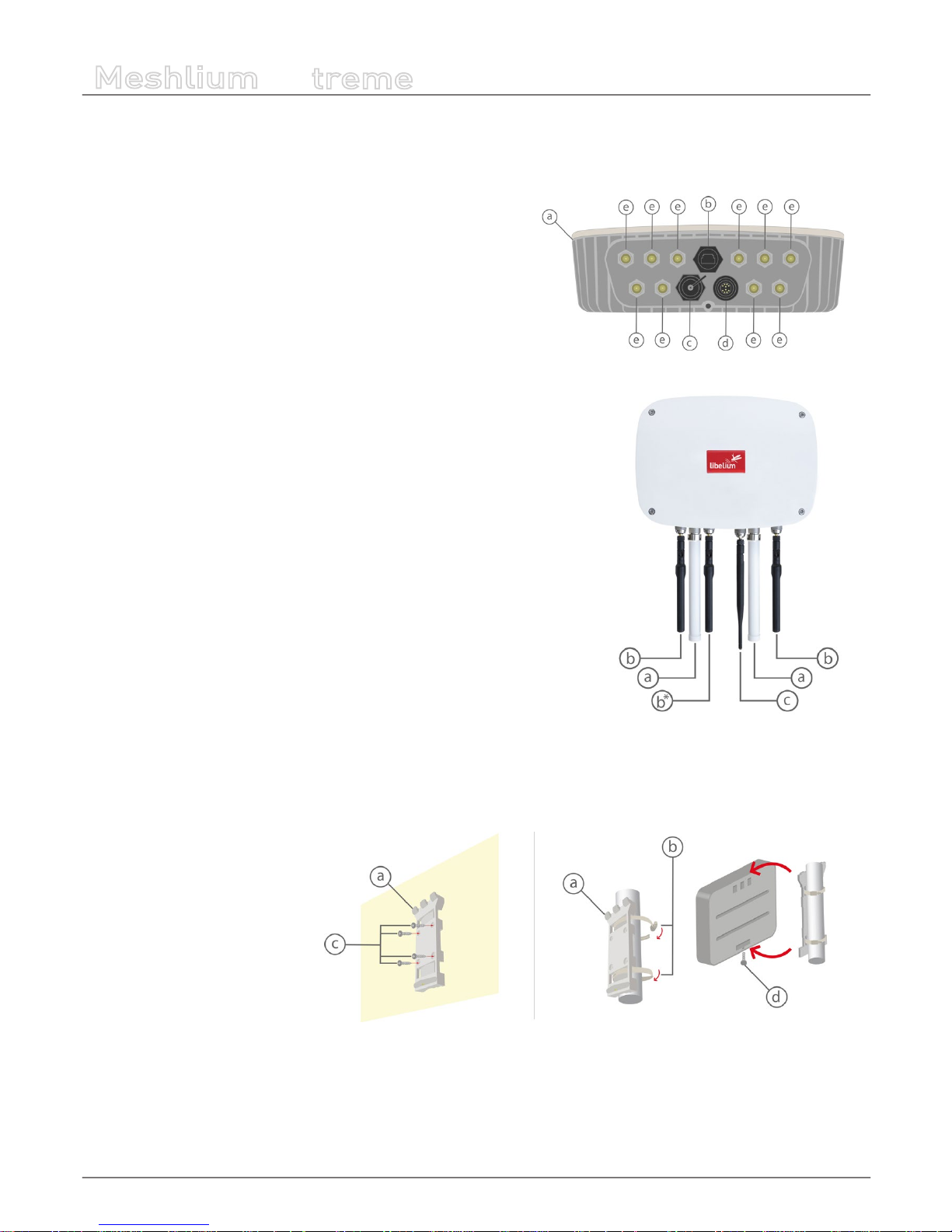
4. Contents of the box
Meshlium
a) IP65 casing
b) Ethernet connector
c) micro-SIM + micro-USB connector
d) Expansion connector
e) Antenna connectors
Antennas
*
a) Dipole 5 dBi (Bluetooth, WiFi, XBee-PRO 802.15.4)
b) 4G / GPS (3 antennas for EU, US or BR models; 2 antennas for AU models)
c) Dipole 4.5 dBi (XBee 868LP, XBee-PRO 900HP)
(*) Number and type of antennas depend on the model purchased.
Fixing
a) Fixing plate
b) 2 metal brackets
c) Screws and wall plugs
d) Mounting screw
-14-
v7.1
Contents of the box
Meshlium
X
treme
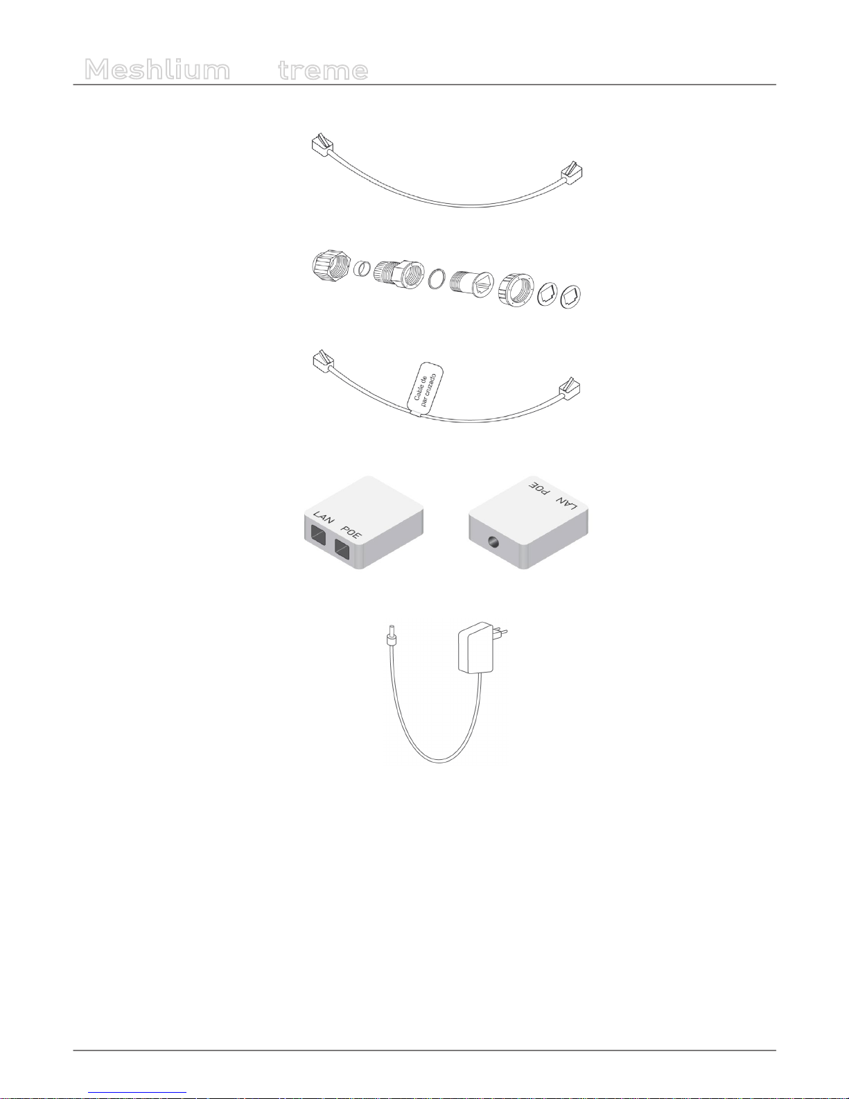
Ethernet cable
IP65 Ethernet cap
Ethernet crossover cable
POE injector
AC/DC adapter
-15-
v7.1
Specications
Meshlium
X
treme
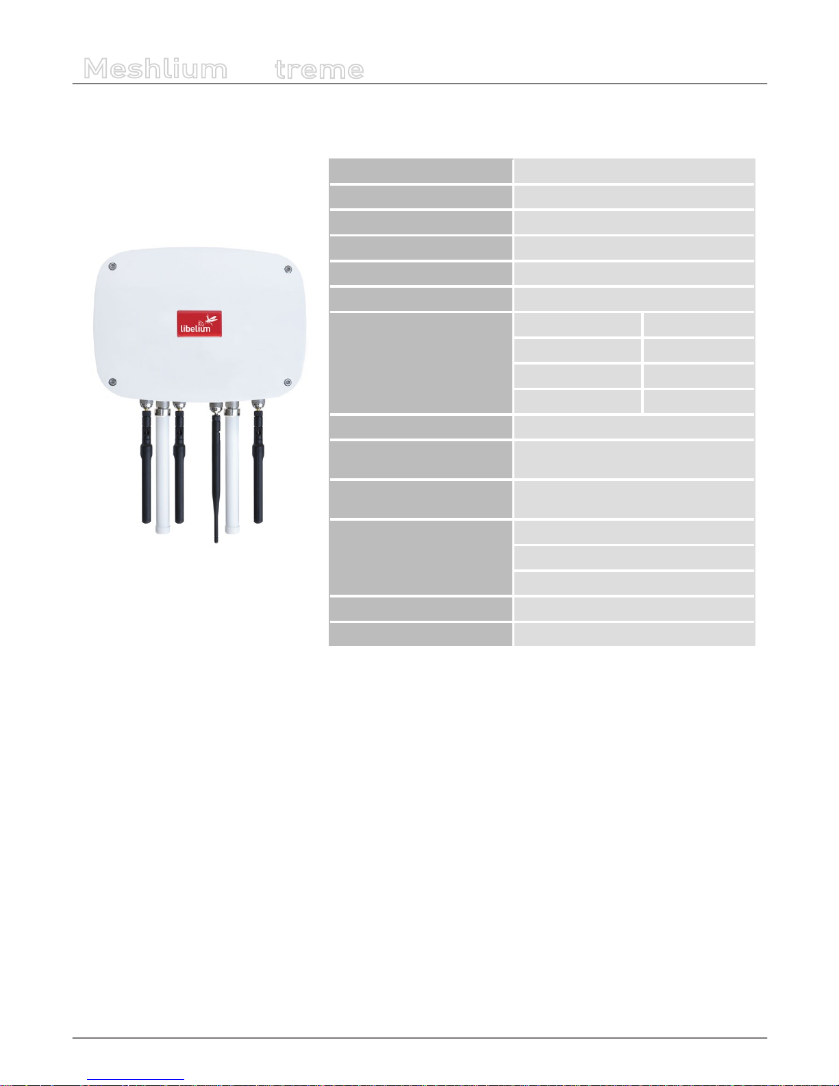
5. Specications
Processor 1 GHz Quad Core (x86)
RAM memory 2 GB (DDR3)
Disk memory 16 GB
Power 6 to 12 W (12 V)
Power source PoE (Power Over Ethernet)
Max current supply 2 A
Enclosure
Material Aluminum
Dimensions 300 x 220 x 87 mm
Weight 2.2 kg
External protection IP65
Temperature range -20 ºC / 50 ºC
Response time to Ethernet
ping
60 s
Time to have all the services
running
60 s
Types of power supply*
AC-220 V (DC-12 V)
Linux, Debian based
Meshlium Manager System
Management software (open source)
Security Authentication WEP, WPA, WPA2, HTTPS
(*) Only with the accessories supplied by Libelium
Figure : Meshlium unit
-16-
v7.1
Specications
Meshlium
X
treme
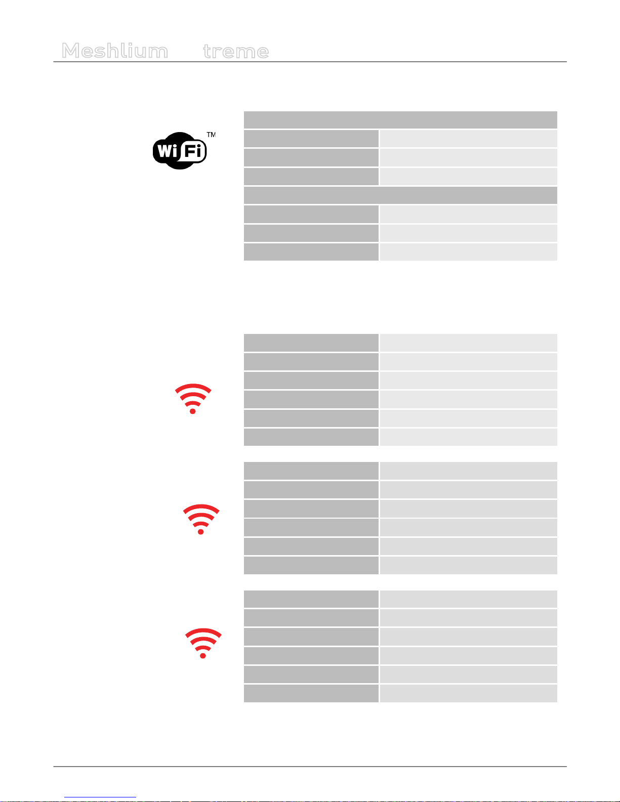
WiFi (2.4 GHz) radio (Access Point/Scanner)
WiFi radio
Chipset Qualcomm Atheros QCA9882
TX power 20 dBm
Range 500 m*
Antenna 5dBi dipole
Type Omni-directional, dipole
Gain 5 dBi
Dimensions 224 x 22 mm
(*) Depending on antenna and line of sight
RF radio modules
Model XBee-PRO 802.15.4
Frequency 2.4 GHz
TX power 18 dBm (10 dBm for EU models)
Rx sensitivity -100 dBm
Antenna 5 dBi dipole
Range 1.6 km (750 m in EU models)*
Model XBee 868LP
Frequency 868 MHz
TX power 14 mW
Rx sensitivity -106 dBm
Antenna 4.5 dBi dipole
Range 8.4 km*
Model XBee-PRO 900HP
Frequency 900 MHz
TX power 24 dBm
Rx sensitivity -110 dBm
Antenna 4.5 dBi dipole
Range 15.5 km*
(*) Depending on antenna and line of sight
-17-
v7.1
Specications
Meshlium
X
treme
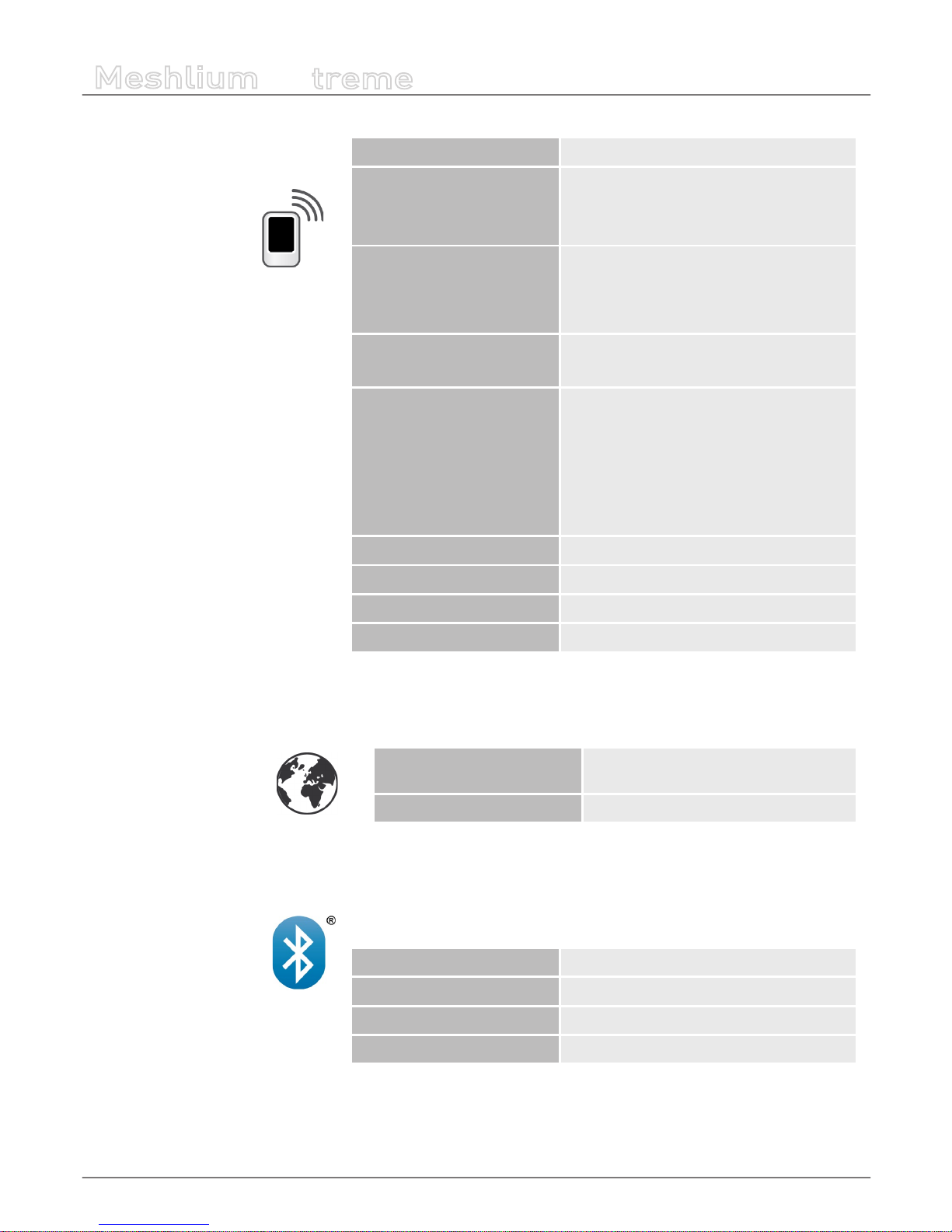
4G/LTE module
Protocols 4G, LTE, 3G, WCDMA, HSPA, UMTS, GPRS, GSM
Frequency bands, EU/BR
version
LTE - 800 (B20) / 1800 (B3) / 2600 (B7)
UMTS - 850 (B5) / 900 (B8) / 2100 (B1)
GSM/GPRS - 900 /1800
Frequency bands, US version
LTE - 700 (B17) / 850 (B5) / AWS1700 (B4) /
1900 (B2)
UMTS - 850 (B5) / 1900 (B2) GSM/GPRS - 850 /
1900
Frequency bands, AU version
LTE - 700 (B17) / 1800 (B3) / 2600 (B7)
(AU models do not support 3G, GPRS or GSM)
Output power
Class 4 (2 W, 33 dBm) @ GSM 850/900
Class 1 (1 W, 30 dBm) @ GSM 1800/1900
Class E2 (0.5 W, 27 dBm)@ EDGE 850/900
Class E2 (0.4 W, 26 dBm)@ EDGE 1800/1900
Class 3 (0.25 W, 24 dBm) @ UMTS
Class 3 (0.2 W, 23 dBm) @ LTE
RX rate Up to 100 Mb/s
TX rate Up to 50 Mb/s
Antenna 4 dBi
SIM card Access via the External micro-SIM socket
GPS Module
Modes
Assisted GPS (A-GPS),
Standalone mode (NMEA frames)
Antenna 4 dBi
The AU models do not have a GPS receiver
Bluetooth Scanner
Protocol Bluetooth 2.1 + EDR Class 2
TX power 3 dBm
Antenna 5 dBi dipole
Range 20-30 m*
(*) Depending on antenna and line of sight
-18-
v7.1
How to use Meshlium
Meshlium
X
treme
6. How to use Meshlium
6.1. Power supply
Meshlium needs a 220 V power connection. The device must be powered with the power source provided by Libelium.
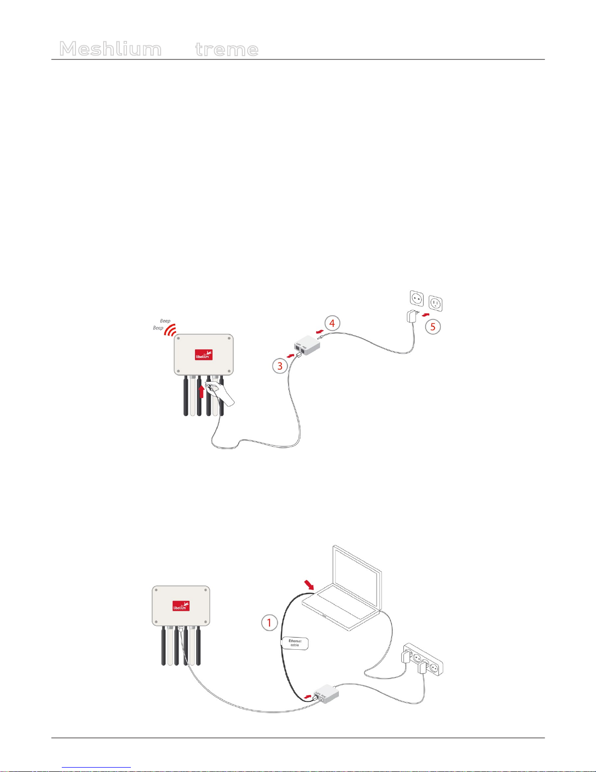
How to connect Meshlium to 220 V (110 V compatible):
• 1. Unscrew the Ethernet connector cap in Meshlium.
• 2. Join the end that has the IP65 protection of the Ethernet cable to the connector and screw the cap on to x it.
• 3. Connect the free end of the cable to the PoE injector input marked as PoE. As explained in the section “Before using
Meshlium”, make sure that the PoE is indoors.
• 4. Take the supplied power adapter and plug it into the corresponding PoE injector connector, labeled as DC.
• 5. Plug the other end of the adapter into the 220 V socket and your Meshlium is now ready to operate.
Note: For equipment powered by an electric outlet, a power outlet must be installed near the equipment, and it must be easily
accessible.
Figure : Connecting Meshlium to 220 V
How to connect Meshlium in order to get access by the Ethernet interface:
• 1. Connect the network crossover cable (it has an identifying label) included in the box to the PoE injector input marked
LAN and to the network socket of your PC as shown in the diagram.
(*) See the “Accessing Meshlium” section in order to see how to get access via wireless.
Figure : Connecting LAN cable to a PC
-19-
v7.1
How to use Meshlium
Meshlium
X
treme
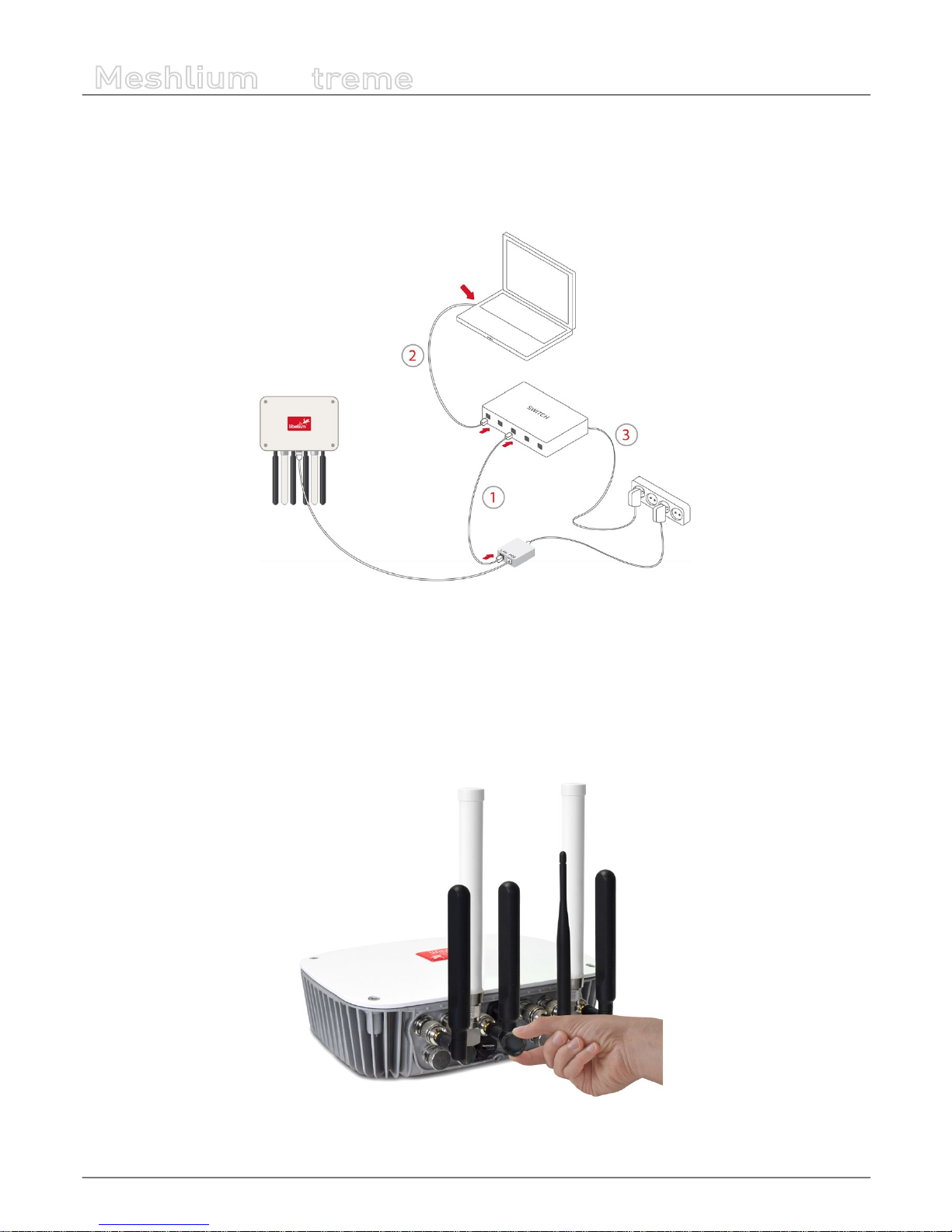
You can also carry out this connection through a switch (not supplied with Meshlium):
• 1. Connect the Ethernet cable (not the crossover) to the PoE input marked LAN and to one of the switch inputs.
• 2. Connect another Ethernet cable to another one of the switch inputs and the opposite end to the network socket of your PC.
(*) See the “Accessing Meshlium” section in order to see how to get access via wireless.
Figure : Connecting LAN cable to a switch
6.2. External SIM socket
The External SIM socket is composed of 2 connectors:
• micro-SIM card
• micro-USB (type B)
Figure : External SIM socket in a Meshlium with 4G/3G/GPRS/GSM module
-20-
v7.1
How to use Meshlium
Meshlium
X
treme
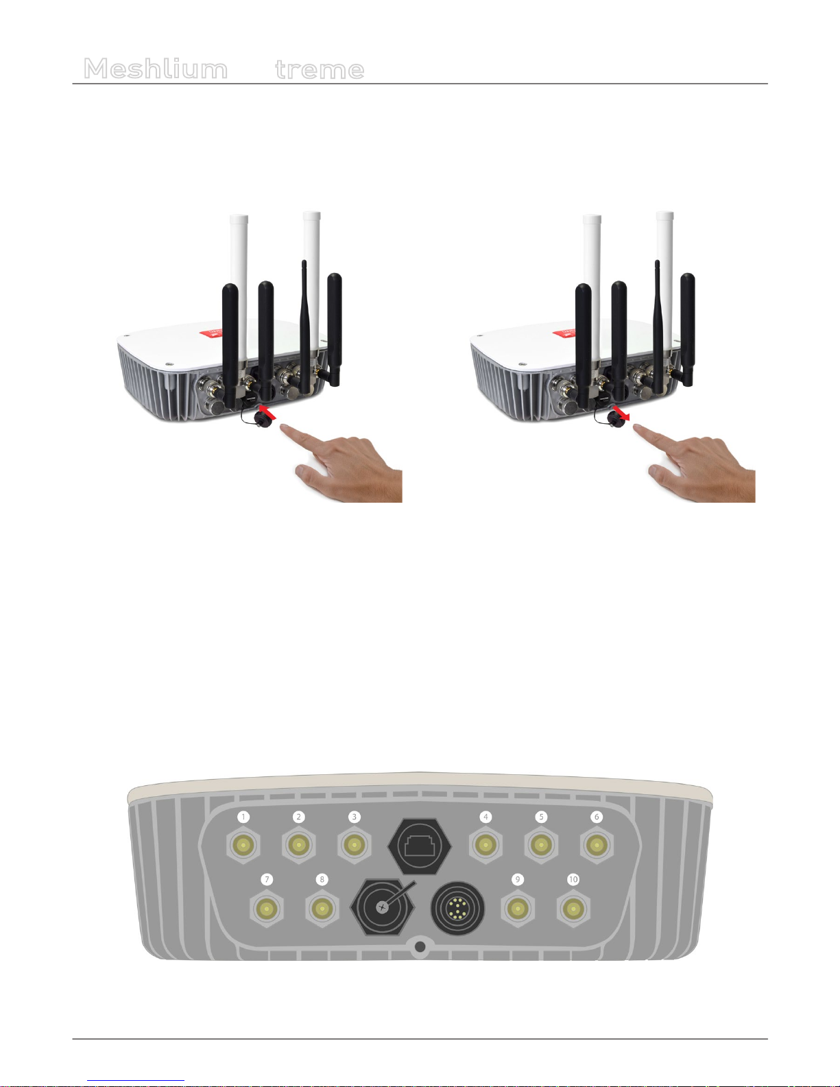
The micro-SIM card connector allows the user to connect the SIM card. You can ask your Mobile Network Operator for a microSIM card. It is better to use a normal micro-SIM card, not a card which can be broken into a nano-SIM card.
The micro-SIM card connector has a push-push mechanism, so it is really easy to remove the card using one nail or a small tool.
To insert the SIM, press until a click is heard. To release the card, press until a click is heard and the spring will push the card free.
Figure : Push-push mechanism External SIM socket
It is very important to turn o Meshlium in a secure way before inserting a micro-SIM card, or removing an existing SIM card. The
user can damage the device if this operation is done with the device on.
Make sure the External SIM socket is closed with its protection cap tightly screwed before an outdoors deployment.
The operation with the micro-USB socket is just the same than with a normal USB socket. A USB OTG cable can be used to plug
in standard A USB connector (like pendrives).
Take into account that the External SIM socket has a limited resistance so please be gentle and push with care.
6.3. How to install the antennas
Every antenna for each technology has a dened position in which it has to be installed. The dierent positions are:
Figure : Antenna socket numbers
-21-
v7.1
How to use Meshlium
Meshlium
X
treme
• WiFi AP – Socket 2
• 4G with adapter n-to-SMA– Socket 1 and 6
• GPS with adapter n-to-SMA – Socket 3
• RF module 802.15.4 – Socket 5
• RF module 868 MHz / 900 MHz with adapter n-to-RP-SMA – Socket 4
• Bluetooth Scanner – Socket 5
• WiFi Scanner – Socket 4
The antennas have to be gently screwed on the connector. Do not force the antenna, if you need too much strength to screw it
is probably being installed in a wrong position.
If you have any reception issue with 4G or GPS, you can try bending the aected antenna in order to improve isolation.
6.4. Installation of the IP65 Ethernet cable
Installation of the IP65 cap:
In order to install the IP65 cap you will need a connector-free RJ45 cable. This cable is NOT included in the Meshlium box.
Important: Make sure that you have a cable long enough to connect Meshlium from its denitive location to the PoE located
indoors. It is not recommended to install Meshlium too far from the PoE injector due to the power loss in the cable. Always test
the device with a cable of the same length before installing.
The Ethernet cable can be used for indoors and outdoors deployments. Just note that its resistance is limited, so in order to
maximize its lifetime in harsh conditions (direct sunlight, extreme temperatures, very wet climate), we advise to protect the
cable with some isolating tube or heat-shrink sleeve. This is also important for installations where insects, birds, rats or other
animals could try to bite the cable.
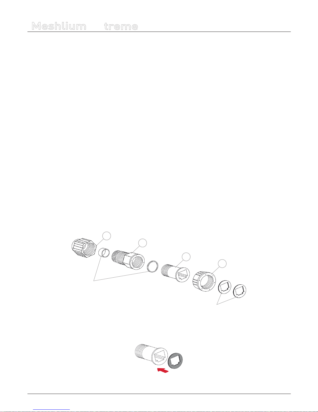
• 1. Take from the Meshlium box the bag containing the parts for installing the IP65 cap. Check that you have all the parts
that appear in the picture.
c
b
d
Joints
Adhesive joints
a
Figure : Cap parts
• 2. Stick one of the supplied adhesive joints to part C.
Figure : Stick joint
-22-
v7.1
How to use Meshlium
Meshlium
X
treme
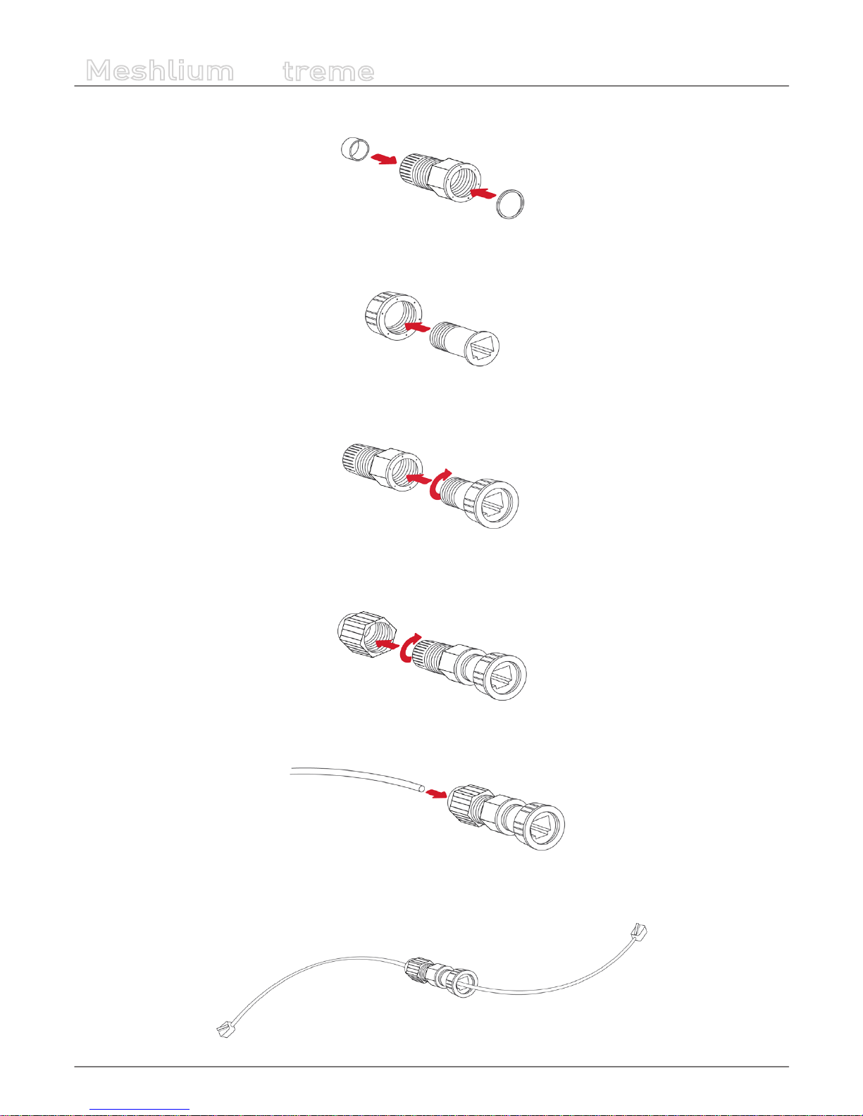
• 3. Introduce the joints into part B as shown in the drawing.
Figure : Introduce joints
• 4. Insert part C into part D.
Figure : Insert part C
• 5. Screw both sets of parts in the direction shown in the diagram.
Figure : Screw both parts
• 6. Partially screw part D to the end.
Figure : Screw part D
• 7. Pass the cable through the tted cap.
Figure : Pass the cable
• 8. Crimp the RJ45 connectors at the ends of the cable (the crimping tool is not supplied with Meshlium).
Figure : Crimp RJ45
-23-
v7.1
How to use Meshlium
Meshlium
X
treme
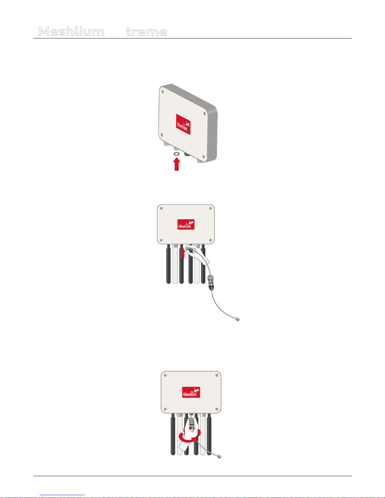
Your IP65 Ethernet cable is now ready for use.
How to connect the IP65 Ethernet cable to Meshlium:
• 1. Take the adhesive joint that has not been used for tting the cap and stick it to the Meshlium Ethernet connector.
Figure : Stick joint
• 2. Connect the end of the Ethernet cable to the Meshlium Ethernet socket.
Figure : Connect RJ45
• 3. Screw part C onto the Meshlium connector. Screw tighter part D to x the cable too. Your Meshlium is now ready to use
outdoors.
Figure : Screw connector and tighten part D
-24-
v7.1
How to use Meshlium
Meshlium
X
treme
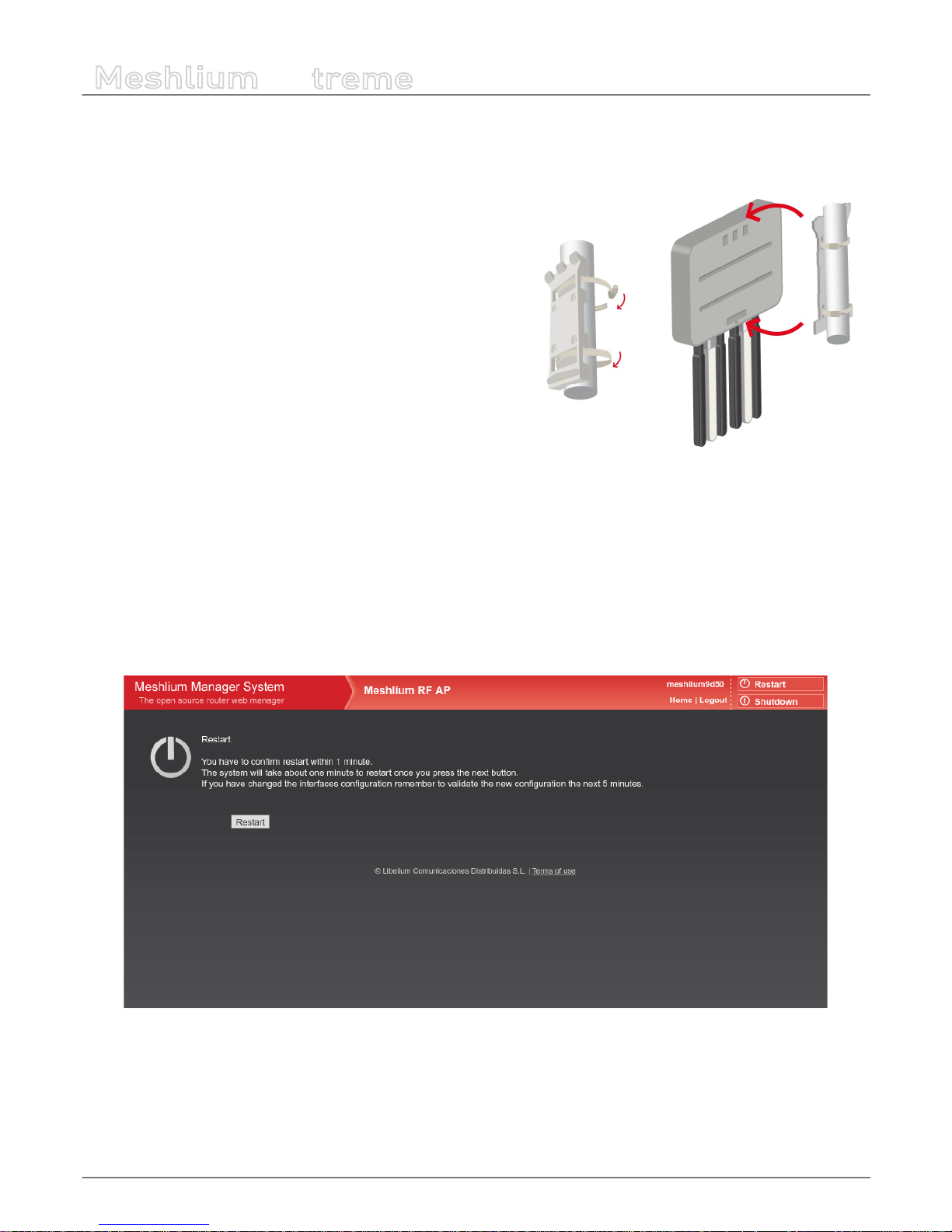
6.5. Installing Meshlium
Meshlium has been designed to operate in a vertical position with the
antennas and connectors facing down. You will nd the required bracket
to mount Meshlium in a pole or in a wall.
To x the bracket to a wall:
• 1. Attach bracket to the wall using wall plugs and screws. Screws
provided are for general use and could not be valid for every surface.
Use hardware adapted for the surface you are installing Meshlium
on.
To x the bracket to a mast:
• 1. Attach the bracket to the mast using the hose clamps. Hose
clamps provided are for 50-70mm circumference masts. If your mast
is thicker, use clamps with the proper metric.
Once the bracket is xed:
• 1. Attach the box to the bracket, tting the three top notches in the holes of the box.
• 2. Secure the screw in the bottom of the box.
6.6. Initialization, restart and shutdown
In order to allow Meshlium to close correctly all the daemons and applications it is important to use the buttons Restart and
Shutdown placed in the upper right corner in the Manager System. This way you will keep maximum the performance and
lifetime of the system.
Figure : Restart screen
Once you click on the Restart or Shutdown button of manager system you have one minute to conrm the operation. If you do
not conrm in that time, you will need to click in the button again to perform the operation.

-25-
v7.1
How to use Meshlium
Meshlium
X
treme
Beep! System
Meshlium includes an internal speaker which will emit “beep!” sounds when initializing, rebooting and shutting down in order
to inform about the state of the process.
Initialization beeps:
• Long beep when Meshlium has nished starting and it is ready to be used
Reboot beeps:
• Long beep when the reboot order is executed
• Initialization beeps when Meshlium starts again
• Do not remove the power cable during this process is carried out
Shutting-down beeps:
• This process could take up to one minute
• Long beep when Meshlium is about to shutdown. A few seconds after the beeps, Meshlium can be unplugged.
• Do not remove the power cable until this process is totally completed
Note: The “beep!” sound is not really loud so you will have to take attention and be close to the Meshlium box in order to hear them
clearly.
Note 2: If Meshlium is unplugged before the acoustic signal of shutdown, internal memory could be damaged. Be sure to wait for
several minutes if you are not sure the beeps sounded.
Note 3: The duration of the reboot or shut-down processes may vary. Make sure you heard the corresponding beeps and be patient.
Note 4: If the user does not follow these instructions, the risk is very high. Meshlium will become unresponsive and inaccessible. This
problem is out of the warranty scope, because it is produced by bad use. The only possible solution will be a repair process in Libelium’s
facilities, paid by the user.
6.7. Setting the time
In order to get all the data stored in the Meshlium local database with the right timestamp, you must adjust the System time.
To do so, go to the “Setting the Time” section, inside the “System Information” chapter in the current guide.
-26-
v7.1
Understanding Meshlium
Meshlium
X
treme
7. Understanding Meshlium
7.1. Concepts
Meshlium is an IoT gateway that may contain up to 4 dierent radio interfaces: a WiFi 2.4 GHz (Access Point), a 4G/3G/GPRS/GSM
and 2 XBee/RF radios. Meshlium also integrates a GPS module for mobile and vehicular applications and may include Bluetooth
and WiFi radios too for scanning applications. These features along with an aluminum IP65 enclosure allows Meshlium to be
placed outdoors.
Meshlium can work as:
• an RF (XBee) to Ethernet router for Waspmote nodes*
• an RF (XBee) to 4G/3G/GPRS/GSM router for Waspmote nodes*
• a WiFi Access Point
• a WiFi to 4G/3G/GPRS/GSM router
• a GPS – 4G/3G/GPRS/GSM real-time tracker
• a smartphone scanner (detects iPhone and Android devices)
* More info about Waspmote at: http://www.libelium.com/waspmote
All the networking options can be controlled from the Manager System, a web interface which comes with Meshlium. It allows
you to control all the interfaces and system options in a secure, easy and quick way.
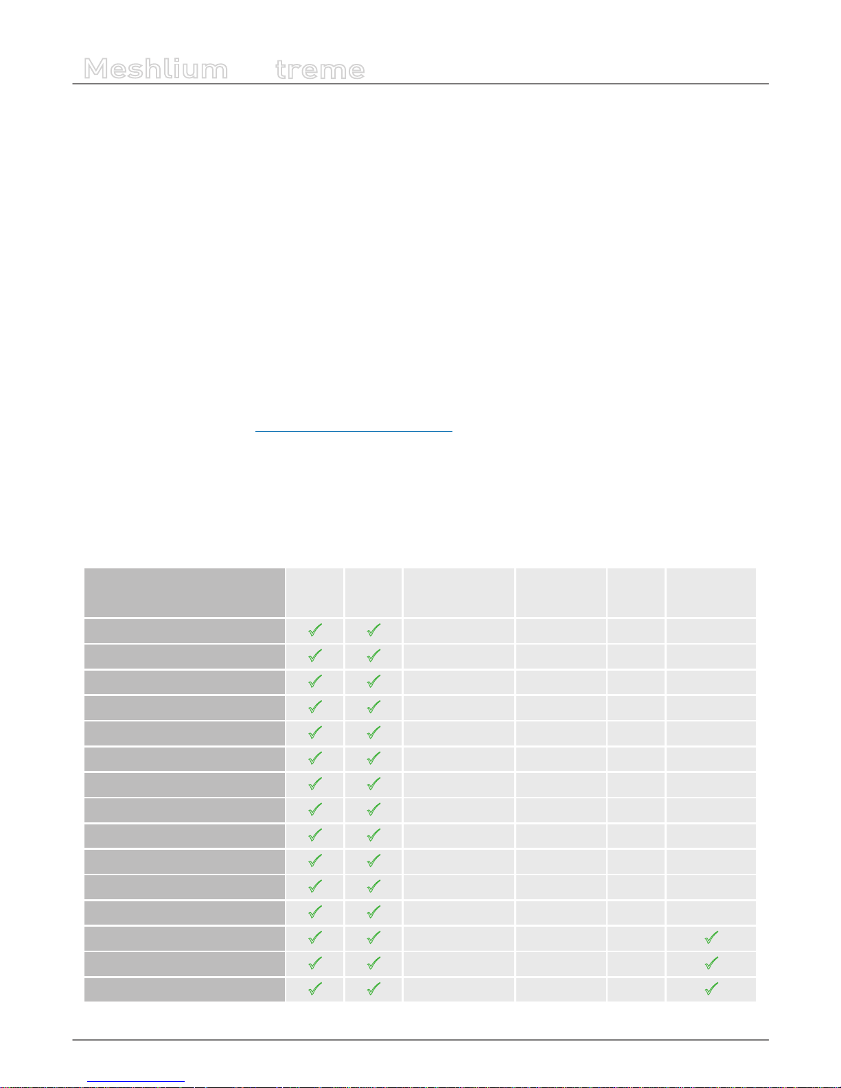
7.2. Meshlium models
There are dierent Meshlium models depending on the radios integrated:
Meshlium model Ethernet WiFi AP 4G/3G/GPRS/GSM 802.15.4 868/900
WiFi &
Bluetooth
scanners
Meshlium 4G 802.15.4 AP 868 EU
P P
EU/BR version EU version 868
Meshlium 4G 802.15.4 AP 900 US
P P
US version World version 900 US
Meshlium 4G 802.15.4 AP 900 BR
P P
EU/BR version World version 900 BR
Meshlium 4G 802.15.4 AP 900 AU
P P
AU version World version 900 AU
Meshlium 4G AP 868 EU
P P
EU/BR version 868
Meshlium 4G AP 900 US
P P
US version 900 US
Meshlium 4G AP 900 BR
P P
EU/BR version 900 BR
Meshlium 4G AP 900 AU
P P
AU version 900 AU
Meshlium 4G 802.15.4 AP EU
P P
EU/BR version EU version
Meshlium 4G 802.15.4 AP US
P P
US version World version
Meshlium 4G 802.15.4 AP BR
P P
EU/BR version World version
Meshlium 4G 802.15.4 AP AU
P P
AU version World version
Meshlium 4G AP Scanner EU/BR
P P
EU/BR version
P
Meshlium 4G AP Scanner US
P P
US version
P
Meshlium 4G AP Scanner AU
P P
AU version
P
Each model with RF modules can have XBee-PRO 802.15.4 and XBee 868LP or XBee-PRO 900HP (depending on the region).
-27-
v7.1
Understanding Meshlium
Meshlium
X
treme
7.3. Storage
The size of the Meshlium hard disk is 16 GB. The Operating System and the Manager System take ~3 GB. This means the space
which can be used to store the data captured and to be used by the applications loaded by the user is:
• 16 GB – 3 GB = 13 GB
Some of this space (7.2 GB) is assigned to the user partition: “/mnt/user”.
The local database les can be found in: “/mnt/user/mysql/MeshliumDB”.
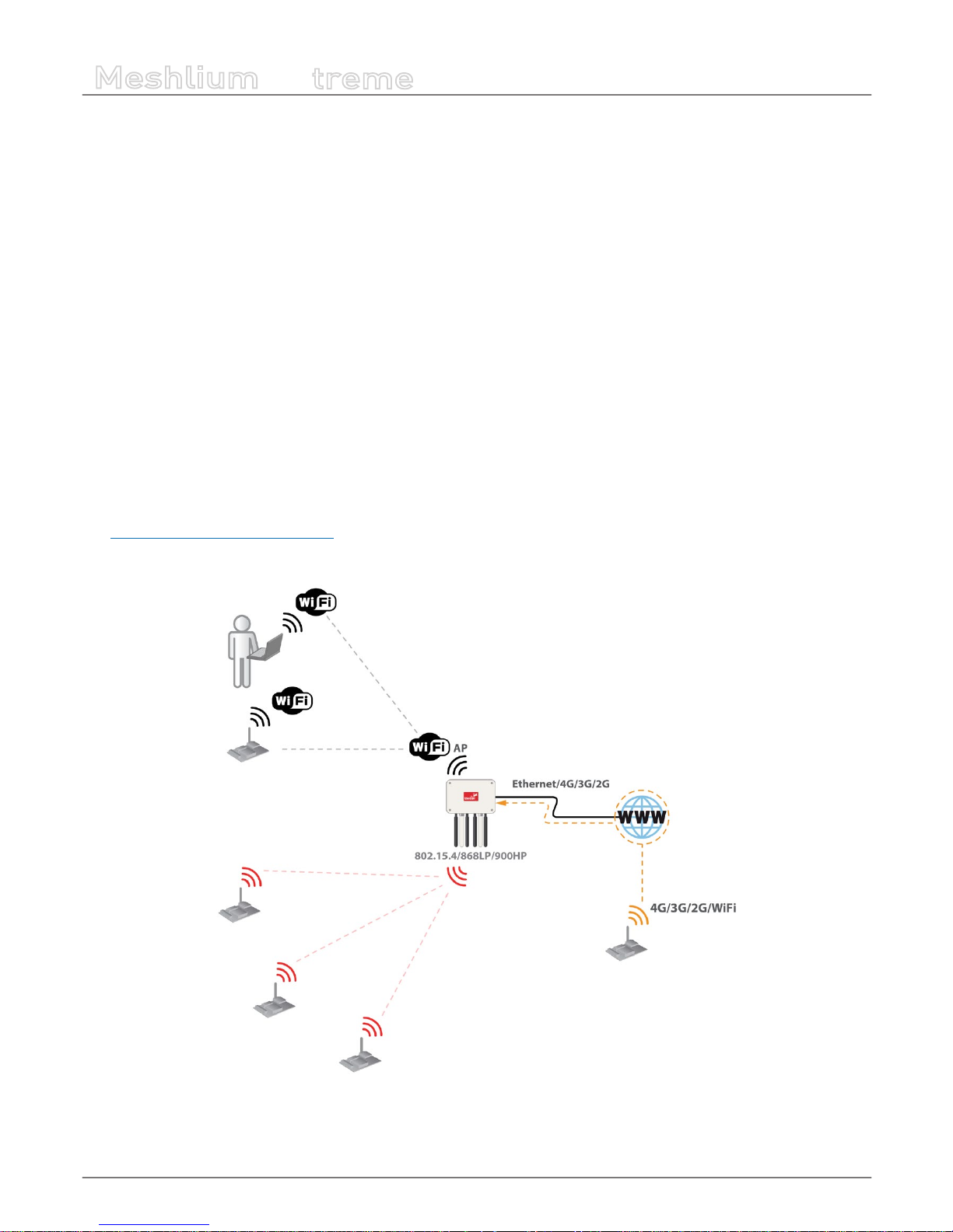
7.4. Application model by model
Meshlium RF 4G AP
Meshlium can take the sensor data which comes from a Wireless Sensor Network (WSN) made with Waspmote sensor devices*
equipped with RF (XBee) radios and send it to the Internet using the Ethernet interface or the 4G/3G/GPRS/GSM interface.
Besides, Waspmotes with GPRS, GPRS+GPS, 3G, 4G or WiFi can send sensor info through the access point or through the Internet
via HTTP protocol. Users can connect directly to Meshlium using the WiFi interface to control it and access to the sensor data.
Users can also connect to Meshlium via WiFi with laptops and smart phones and get access to the Internet (as a common Access
Point).
(*) http://www.libelium.com/waspmote
Figure : Meshlium RF 4G AP
-28-
v7.1
Understanding Meshlium
Meshlium
X
treme
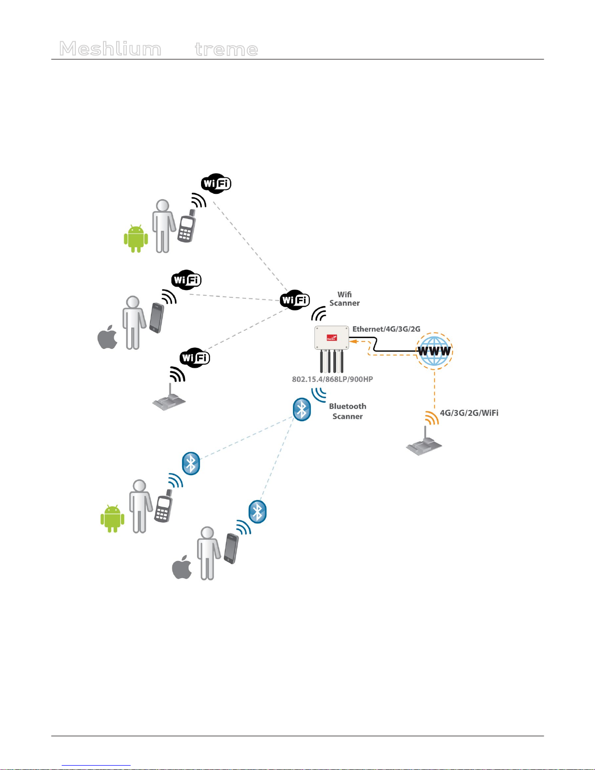
Meshlium Scanner 4G AP
It allows to detect Smartphones (iPhone, Android) and in general any device which works with WiFi or Bluetooth interfaces.
The collected data can be send to the Internet by using the Ethernet interface or the 4G/3G/GPRS/GSM connectivity. Besides,
Waspmotes with GPRS, GPRS+GPS, 3G, 4G or WiFi can send sensor info through the access point or through the Internet via
HTTP protocol. Users can connect directly to Meshlium using the WiFi interface to control it and access to the sensor data. Users
can also connect to Meshlium via WiFi with laptops and smart phones and get access to the Internet (as a common Access Point).
Figure : Meshlium Scanner 4G AP
-29-
v7.1
Accessing Meshlium – make it easy!
Meshlium
X
treme
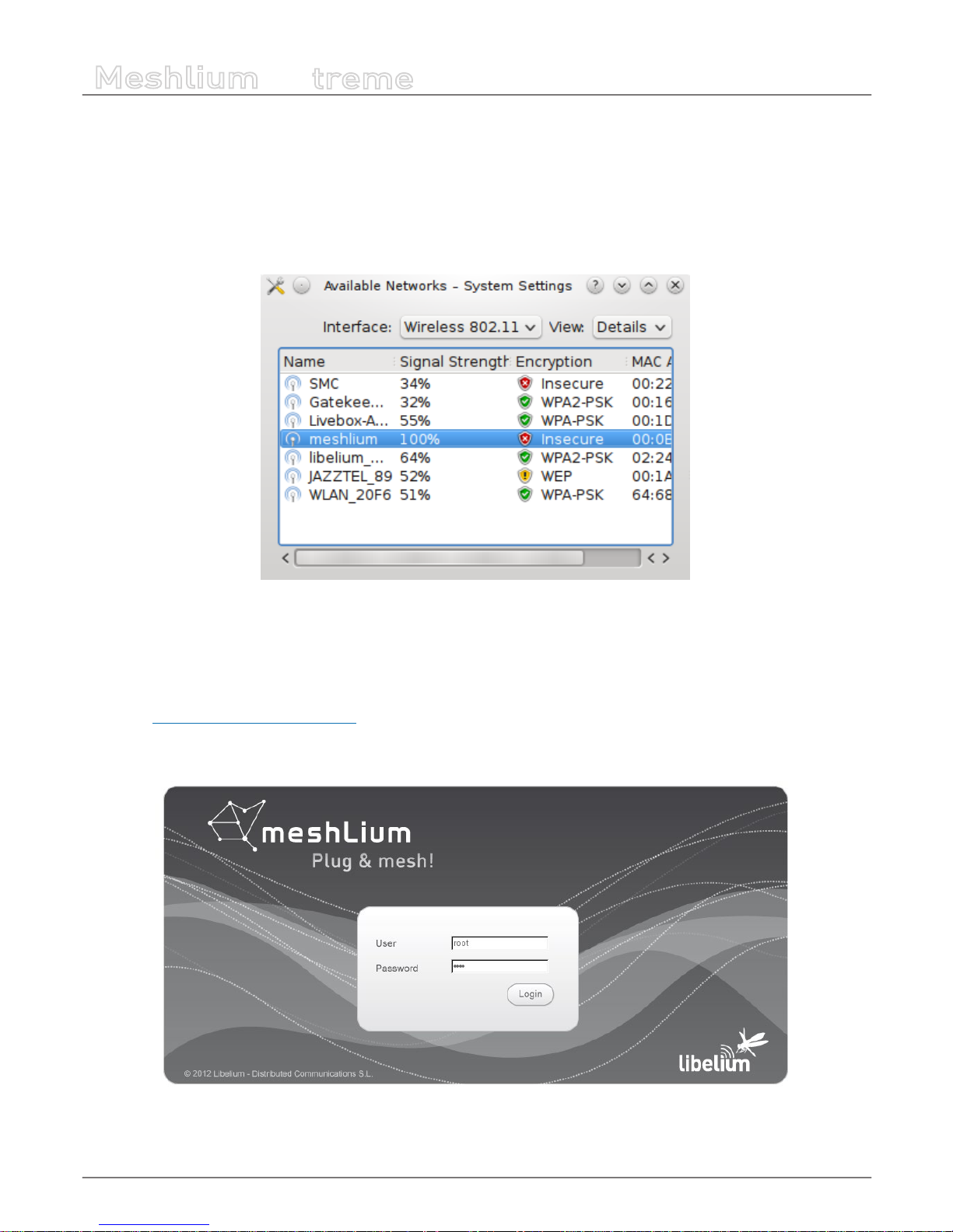
8. Accessing Meshlium – make it easy!
Meshlium comes with all the radios ready to be used. All the Meshlium units come with the WiFi Access Point ready, so that users
can connect using their WiFi devices. Connect the Ethernet cable to your network hub, restart Meshlium and it will automatically
get an IP address from your network using DHCP.
Then access Meshlium through the WiFi connection. First of all, search the available access points and connect to “MeshliumXXXX”.
The four digits at the end allow to identify dierent Meshliums when working near each other.
Figure : List of AP with Meshlium network
No password is needed as the network is open (you should change it later in the WiFi AP interface options). When you select it,
Meshlium will give an IP address from the range 10.10.10.10 – 10.10.10.250.
Now you can open your browser on your PC, tablet or smartphone and access the Meshlium Manager System:
• URL: http://10.10.10.1/ManagerSystem
• user: admin
• password: libelium
Figure : Manager System login screen

-30-
v7.1
Accessing Meshlium – make it easy!
Meshlium
X
treme
Figure : Manager System landing page
If your network does not oer DHCP service, Meshlium starts with a default IP address (192.168.1.100). In this case you can
connect Meshlium through the WiFi connection (which is always available) or with the crossover cable provided with Meshlium.
If you want to access to the Manager System using the crossover Ethernet cable go to:
• URL: http://192.168.1.100/ManagerSystem
• user: admin
• password: libelium
-31-
v7.1
Network interfaces setup
Meshlium
X
treme
9. Network interfaces setup
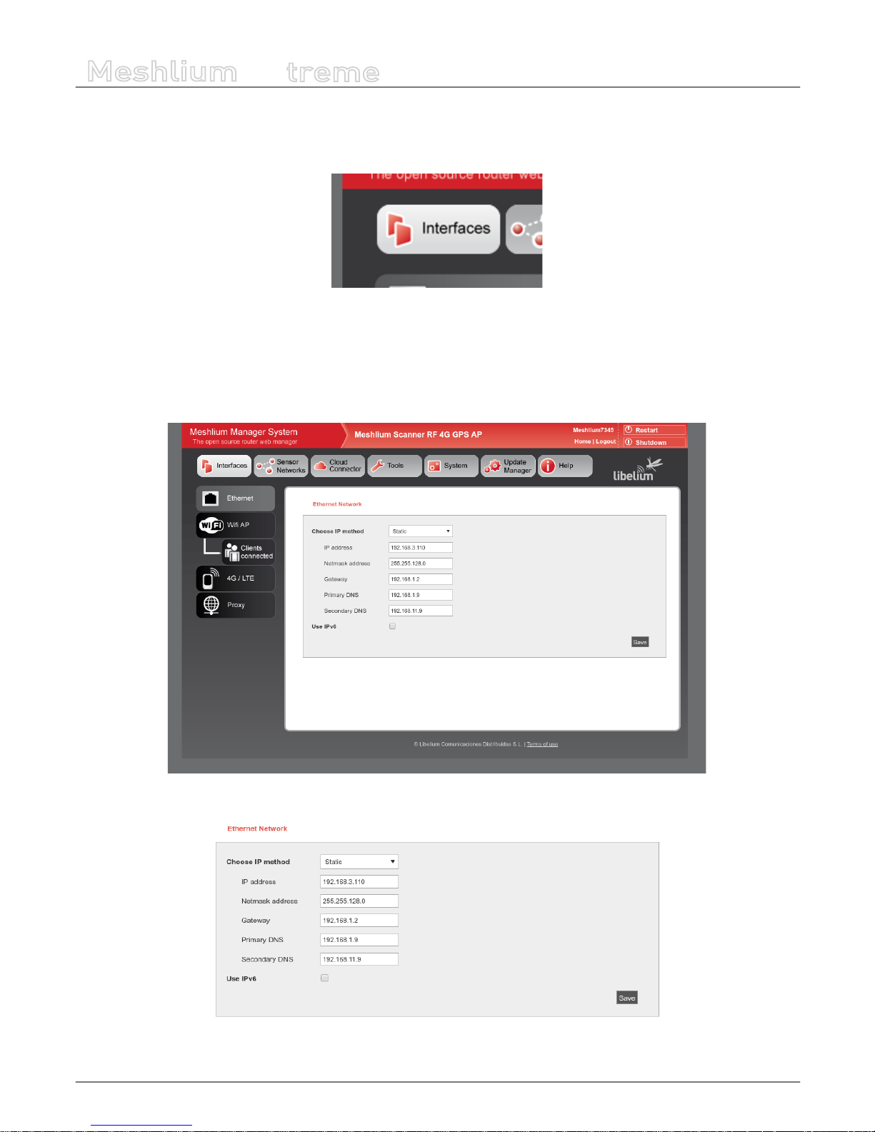
Access the network interfaces setup clicking on the button “Interfaces”:
Figure : Interfaces setup plugin
9.1. Ethernet setup
By default Meshlium comes with the Ethernet interface activated to get dynamically the IP using the DHCP service. In case a
static conguration is required the next parameters can be congured:
Figure : Ethernet setup
Figure : Ethernet setup form

-32-
v7.1
Network interfaces setup
Meshlium
X
treme
You can also use IPv6 (Internet Protocol version 6) by setting the check box “Use IPv6”. IPv6 is a version of the Internet Protocol
(IP) intended to replace IPv4. The next parameters can be congured:
Figure : IPV6 setup
In many cases, IPv6 addresses are composed of two logical parts: a prex of 64-bit (2001::) and a 64 bit part that is generated
automatically from the MAC address of the interface.
The button “Generate IPv6 address” performs this task.
After saving the new options and once you have restarted Meshlium you have to validate the new conguration before the next
5 minutes, if not, the factory default conguration will be restored to avoid leaving Meshlium without connectivity. See section
“Network setup conrmation” for more information.
To check IPv6 conguration, after save and restart Meshlium, go to Tools → Ping. Select Ethernet (IPv6), by default ipv6.google.
com appears as destination host.
Figure : Ping IPv6 with name

-33-
v7.1
Network interfaces setup
Meshlium
X
treme
If your Internet Service Provider does not support external IPv6 addresses yet, you can change it to a local address.
Figure : Ping IPv6 with address
Then press “Do Test”. If something like next image appears, you have IPv6 correctly congured.
Figure : Ping results

-34-
v7.1
Network interfaces setup
Meshlium
X
treme
9.2. WiFi Access Point setup
Meshlium is a WiFi Access Point and can supply network connectivity trough WiFi. The most useful feature of the AP is to provide
access to Manager System from a tablet or laptop without any physical connection with Meshlium.
By default the AP hast the ESSID “meshliumXXXX” where XXXX are the last four digits of Ethernet MAC. This allows to identify
dierent Meshliums installed nearby.
Figure : WiFi Access Point setup
9.2.1. Conguration
There three sections in the conguration page: Network, Radio and Security.
Network
Here you can change the IP of the device in the network and the DHCP setup. Here can be setup:
• IP address of the AP.
• Netmask of the Address.
• DHCP range. The address range in the DHCP setup must be inside the network dened by the IP address and netmask of
the AP.
• DHCP lease time.
Figure : WiFi AP Network setup

-35-
v7.1
Network interfaces setup
Meshlium
X
treme
Radio
These are specic WiFi parameters. Here can be setup:
• ESSID of the network. This is the name that appear in the devices that are searching WiFi networks. It can be public or
hidden, allowing only connections manually started.
• Channel. It is possible to change the radio channel which is used for transmission, according to the next diagram.
Figure : WiFi radio channels
• Protocol. It is possible to use 802.11g and 802.11n.
• Tx power. It allows to control the transmission power, thus the range of the AP.
Figure : WiFi radio settings
Security
The WiFi AP can be protected with encryption. WEP, WPA and WPA2 are available.
WEP is enabled in the 5 and 13 characters congurations while WPA-PSK can be used with a password from 8 to 63 characters.
We recommend use WPA2 in order to get the a good security in the network.
Figure : WiFi AP WEP setup

-36-
v7.1
Network interfaces setup
Meshlium
X
treme
Figure : WiFi AP WPA2
Saving
After saving the setup, a message will warn the user about setup conrmation. A reboot is needed to apply new settings. The
setup has to be conrmed within 5 minutes after reboot. More info in “Network setup conrmation”.
Figure : Conrmation warning
9.2.2. Clients connected
This section shows the list of clients connected to the WiFi AP, showing information like the MAC address and the IP assigned. It
is a quick way to know how many devices are connected and who are they.
Figure : Clients connected

-37-
v7.1
Network interfaces setup
Meshlium
X
treme
9.3. Network setup conrmation
After changing Ethernet or WiFi AP setup, a reboot is needed to apply new settings. After this reboot, the user has to conrm
the settings in order to denitely apply them. If after 5 minutes of the reboot the user has not conrmed the new settings, last
validated settings will be applied again. If there are no validated settings, default settings will be applied.
In the conrmation screen the user can select to conrm new settings, change to last validated settings or change to default
settings. All the information of every setup will be shown. After the conrmation is done, the new settings will be stored as last
validated settings for future conrmations.
The system will show a conrmation window for every setting changed, one for Ethernet setup and one for WiFi AP setup, so
it can be independently conrmed.
Figure : Conrmation screen

-38-
v7.1
Network interfaces setup
Meshlium
X
treme
9.4. 4G setup
This plugin allows to setup the parameters of the modem connection. There is a list with some initial congurations depending
on the country and the operator. However, this list may not be updated with the last valid conguration of your mobile provider.
Ask your mobile company for the information required to connect (APN, Username, Password) and add the PIN code of the SIM
card used (leave empty if there is no PIN). We recommend to disable the PIN in the SIM card as this will make easier the test and
validation process and will avoid to block the SIM card.
Figure : 4G setup plugin
After setting the 4G parameters and before save them you can test your connection through the “Connect now” button. It will
try to connect to your carrier and get a valid IP. Once the connection has been made the default gateway of the machine is
changed so all the clients connected through WiFi will reach the Internet via 4G.
Important: once you get a valid 4G IP through the “Connect now” button, you will not be able to access Meshlium via Ethernet
unless you are connected through the same Local Area Network. For this reason we recommend to make all the tests using the WiFi
connection.
Figure : 4G connecting
-39-
v7.1
Network interfaces setup
Meshlium
X
treme
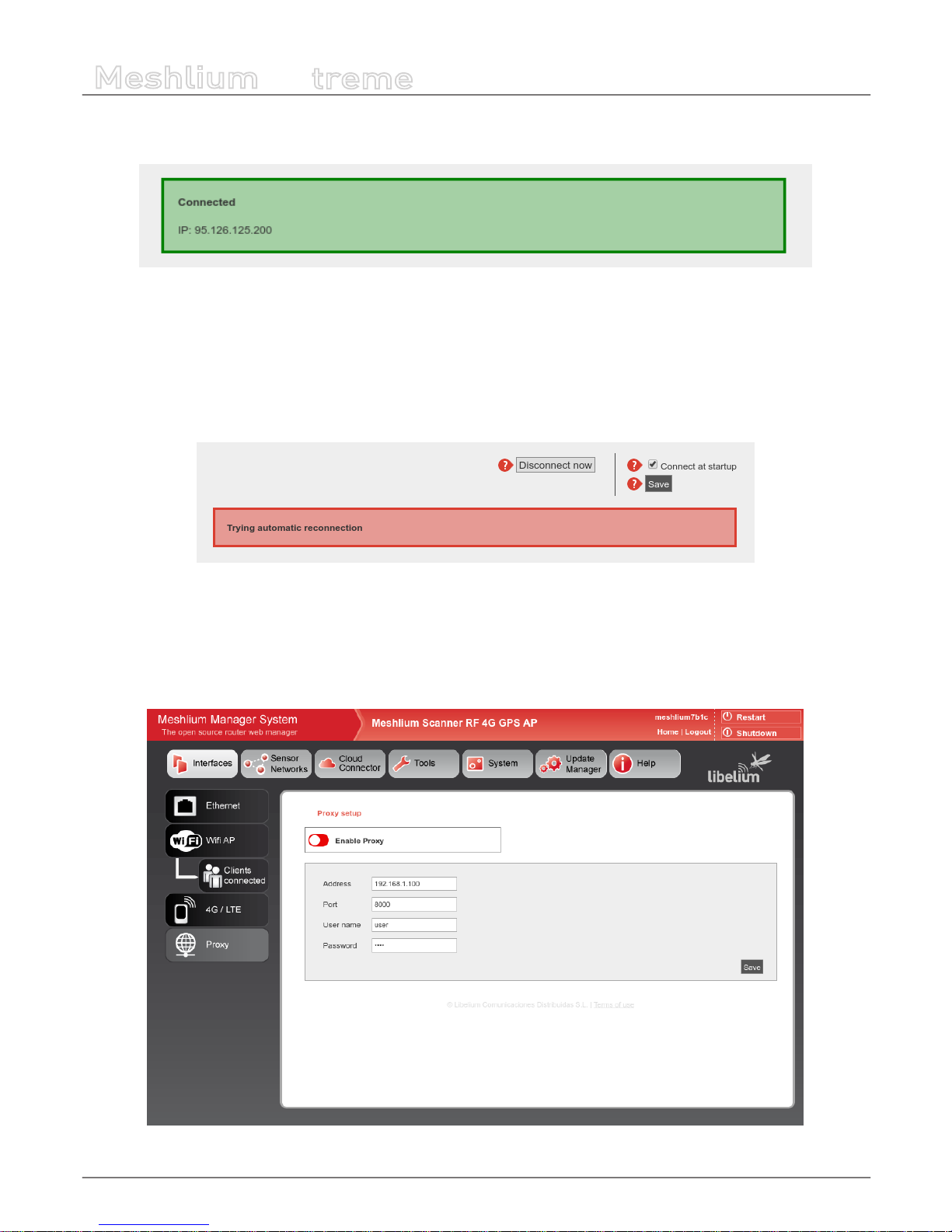
If connection is established, the IP will be shown in the interface. Once the modem is connected a process will check the
connection every 15 minutes and will try to reconnect in case of disconnection.
Figure : 4G successfully connected
Once validated your settings press the Disconnect button and save your conguration. If you want the 4G to be the Default
Gateway of Meshlium each time it starts just activate the service in the “Set as Default Gateway” check box before saving. Setting
this on will connect to the Internet using the 4G radio each time Meshlium restarts.
If any problem is preventing the device to connect at boot or to reconnect after a connection fall, a message will be displayed
in the plugin. The user can manually stop automatic reconnection by pressing “Disconnect now” button.
Figure : 4G trying to reconnect
9.5. Proxy setup
This plugin allows to setup an HTTP proxy for some features of Meshlium. Here can be congured the proxy address, the port
and the credentials (leave blank if not authentication needed).
Figure : Proxy setup plugin

-40-
v7.1
Network interfaces setup
Meshlium
X
treme
The proxy can be enabled or disabled from the control of the interface.
Figure : Proxy enable control
Figure : Proxy disable control
Note: Currently the proxy feature is only available for visualizer plugin. This feature will be gradually included in other services.
-41-
v7.1
Wireless Sensor Networks
Meshlium
X
treme
10. Wireless Sensor Networks
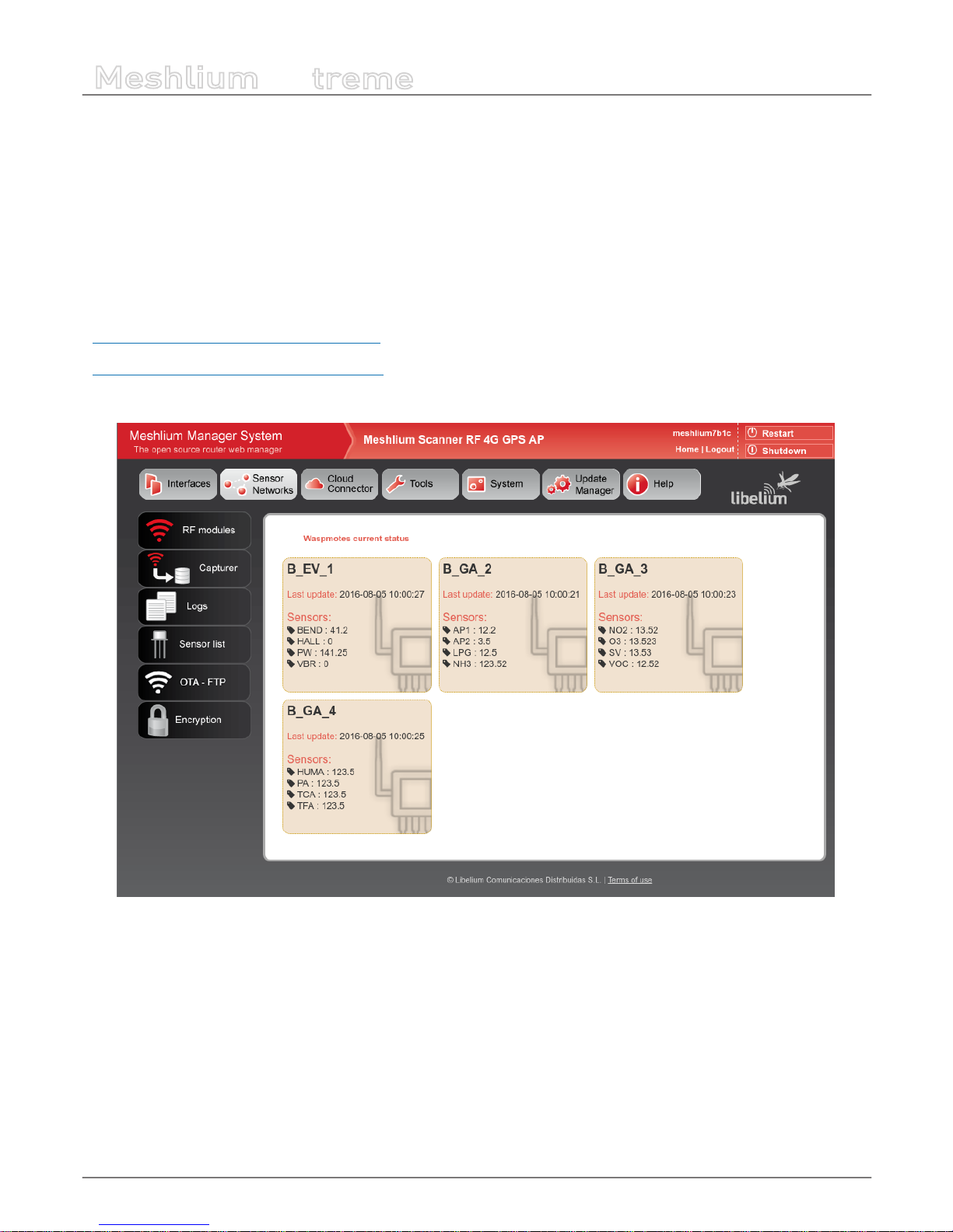
10.1. Meshlium and Waspmote
One of the main applications of Meshlium is being a gateway for Wireless Sensor Networks based on Waspmote and Plug &
Sense! devices. These are sensor nodes that can work with dierent communication technologies like WiFi, 4G or XBee among
others. More than 70 sensors are already available and a complete open source IDE (API libraries + compiler) make really easy
to start working with the platform.
More info at:
http://www.libelium.com/products/waspmote/
http://www.libelium.com/products/plug-sense/
In the main page of “Sensor Networks” tab will be shown the devices in the system showing the last received data.
Figure : Nodes with last data

-42-
v7.1
Wireless Sensor Networks
Meshlium
X
treme
10.2. Receiving and storing data
10.2.1. Receiving trough RF communications
10.2.1.1. RF module setup
Meshlium can equip three dierent RF modules: XBee-PRO 802.15.4 (2.4 GHz), XBee 868LP (868 MHz) and XBee-PRO 900HP (900
MHz). It can equip several modules at the same time.
RF modules setup can be found in:
Sensor Networks → RF modules
The plugin will show a tab for each module detected in the device.
10.2.1.1.1. XBee-PRO 802.15.4 radio setup
Figure : XBee-PRO 802.15.4 setup

-43-
v7.1
Wireless Sensor Networks
Meshlium
X
treme
In this module the parameters to setup are:
• PAN ID: Personal Area Network ID (also known as Network ID). It is the identier of the network. It has to be the same in all
the nodes in order to be able to send data to this Meshlium.
• Channel: Frequency channel used for transmissions.
• Network Address: User dened identier for the node in the network. 4 hexadecimal digits (MY).
• Node ID: readable name set for the device, by default “Meshlium”. Up to 20 characters.
• Power level: [0-4] By default 4.
• Encrypted mode: Internal XBee AES 128 bits encryption. Disabled by default.
• Encryption key: 16 characters.
• MAC: 64 bits hardware address of the module. It is a read-only value divided in two parts:
- MAC-high: 32 bits (8 hexadecimal digits)
- MAC-low: 32 bits (8 hexadecimal digits)
This setup must be consistent with those set on the Waspmote and Plug and Sense nodes.
In the bottom part of the interface, the button “Check status” allows to check if the module setup is concordant with values
shown in the interface. The button “Save” will write the parameters in the module.
Both process (“Save” and “Check status”) require the sensorParser daemon to be stopped. This means no frames will be received
while executing this actions. Be patient this can take up to 1 minute to nish.

-44-
v7.1
Wireless Sensor Networks
Meshlium
X
treme
10.2.1.1.2. XBee 868LP radio setup
Figure : XBee 868LP setup
In this module the parameters to setup are:
• PAN ID: Personal Area Network ID (also known as Network ID). It is the identier of the network. It has to be the same in all
the nodes in order to be able to send data to this Meshlium.
• Node ID: readable name set for the device, by default “Meshlium”. Up to 20 characters.
• Preamble: An extension to PAN ID. It needs to be the same in the nodes too.
• Channel: This module allow to select the channels that can be used. The module automatically selects the channel for the
communication between available ones. Once the channels are selected, the plugin generates the “Channel Frequency
Mask” (read-only 8 hex digits) that the needs to be set in the nodes.
• Power level: [0-4] By default 4.
• Encrypted mode: Internal XBee AES 128 bits encryption. Disabled by default.
• Encryption key: 16 characters.
• MAC: 64 bits hardware address of the module. It is a read-only value divided in two parts:
- MAC-high: 32 bits (8 hexadecimal digits)
- MAC-low: 32 bits (8 hexadecimal digits)

-45-
v7.1
Wireless Sensor Networks
Meshlium
X
treme
10.2.1.1.3. XBee-PRO 900HP radio setup
Figure : XBee-PRO 900HP setup
In this module the parameters to setup are:
• PAN ID: Personal Area Network ID (also known as Network ID). It is the identier of the network. It has to be the same in all
the nodes in order to be able to send data to this Meshlium.
• Node ID: readable name set for the device, by default “Meshlium”. Up to 20 characters.
• Preamble: An extension to PAN ID. It needs to be the same in the nodes too.
• Channel: This module allow to select the channels that can be used. The module automatically selects the channel for the
communication between available ones. Once the channels are selected, the plugin generates the “Channel Frequency
Mask” (read-only 16 hex digits) that the needs to be set in the nodes. In the bottom part of the interface is shown the
minimum number of channels that have to be selected.
• Power level: [0-4] By default 4.
• Encrypted mode: Internal XBee AES 128 bits encryption. Disabled by default.
• Encryption key: 16 characters.
• MAC: 64 bits hardware address of the module. It is a read-only value divided in two parts:
- MAC-high: 32 bits (8 hexadecimal digits)
- MAC-low: 32 bits (8 hexadecimal digits)

-46-
v7.1
Wireless Sensor Networks
Meshlium
X
treme
10.2.1.2. Encryption setup
Link layer key management (AES-128)
This feature is provided by XBee modules.
Encryption is this layer provided through the AES 128b algorithm. Specically through the type AES-CTR. In this case the Frame
Counter eld has a unique ID and encrypts all the information contained in the Payload eld which is the place in the link layer
frame where the data to be sent is stored. The way in which the libraries have been developed for module programming means
that encryption activation is as simple as running the initialization function and giving it a key to use in the encryption.
{
xbee.encryptionMode(1);
xbee.setLinkKey(key);
}
In Manager System, on Sensor Network section, users can encrypt messages on link layer. It can be achieved by setting the
parameters:
• Encrypted mode: true/false (by default false)
• Encryption Key: Must be 16 characters
See section “XBee module setup” for more details about setting encryption.
10.2.1.2.1. Application layer key management
Meshlium is capable to properly receive encrypted data from Waspmote. The coding process is made in the application layer, so
it is Waspmote and Meshlium processor and not XBee module who encrypts and decrypts the messages.
The user have to set a key for the encryption in Waspmote and Meshlium.
In Manager System it can be found:
Sensor Networks → Encryption
Figure : Encryption key setup
For each Waspmote can send frames to Meshlium, Waspmotes keys can be added to an encryption Key le. In this interface the
user must specify the node ID and the Waspmote AES secret key (128, 192 or 256 bits).
After dening the above elds to press the button “Add Waspmote”. A new entry is generated in the left list.
To delete Waspmote of list, select the Waspmote and press “Delete Waspmote”. The encrypted frames received from this node
cannot be decrypted anymore.
The AES secret key is necessary to recognize the frames sent each Waspmote to Meshlium.

-47-
v7.1
Wireless Sensor Networks
Meshlium
X
treme
Figure : Encryption in communications
Once the user has properly set the AES keys associated to every waspmote, receiving AES encrypted frames in Meshlium is a
straightforward process.
As an encrypted frame arrives to Meshlium, sensorParser program takes the appropriate key for the Waspmote ID. The frame is
decoded with the key and the information is extracted to the sensor database.
Bear in mind that to use this feature, the frame have to be created with the Waspmote libraries for AES frames. You can see
further information about this in the Waspmote guides.
http://www.libelium.com/waspmote
10.2.1.3. Capturing and storing sensor data from RF module
Meshlium will receive the sensor data sent by Waspmote and Plug and Sense using the RF radio and it will store the frames in
the local database.
That can be done in an automatic way thanks to the Sensor Parser.
The Sensor Parser is a software system which is able to do the following tasks in an easy and transparent way:
• receive frames from XBee modules (with the Data Frame format)
• parse these frames
• store the data in the local database
Besides, the user can add his own sensors, and the data will be parsed in the database too. In order to add your own sensor
frames properly go to the section “Sensor list”.
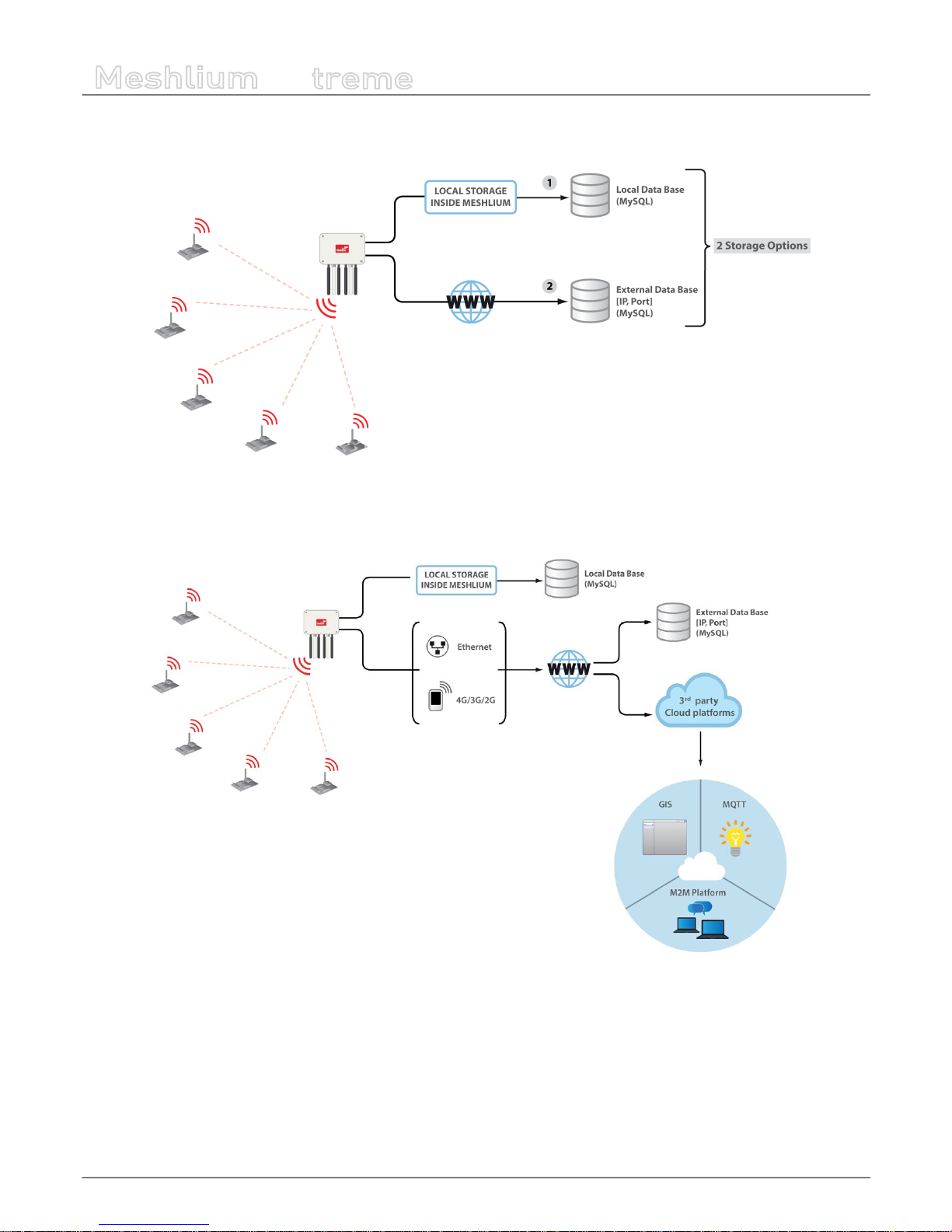
We can perform two dierent storage options with the frames captured:
• Local database
• External database
-48-
v7.1
Wireless Sensor Networks
Meshlium
X
treme
All the data is stored in the local database in the rst place, then it can be synchronized to an external database as per user
needs.
Figure : Storage options
The data stored can be synchronized too to external services using the Internet connection.
Figure : External synchronization options

-49-
v7.1
Wireless Sensor Networks
Meshlium
X
treme
10.2.2. Receiving trough 4G / WiFi / Ethernet (HTTP)
Figure : HTTP data reception
Meshlium accepts POST and GET requests in any of its interfaces so Waspmotes are capable of sending frames, through GPRS,
3G, 4G or WiFi modules, via HTTP requests. Meshlium, through HTTP requests is capable of:
• receive frames from 4G/3G/GPRS/GSM, WiFi or Ethernet via HTTP
• parse these frames
• store the data in local Database
• synchronize the local Database with an external database
Frames received by this method are stored the same way that RF frames, and are identically processed at synchronization stage.
No conguration of any kind is needed to use HTTP. If HTTPS is needed, certicate conguration would be needed in many cases
(self signed certicate is included with Meshlium).
Like the case of RF modules reception, the user can add his own sensors.
10.3. Capturer
The Capturer plugin is where the user can check most recent data received in order to check if the nodes are sending information.
It can be found in:
Sensor Networks → Capturer

-50-
v7.1
Wireless Sensor Networks
Meshlium
X
treme
Capturer plugin have several tabs where the user can see recent data received, manage external database synchronization and
perform some local database operations.
Figure : Capturer plugin

-51-
v7.1
Wireless Sensor Networks
Meshlium
X
treme
10.3.1. Local database
Meshlium has a MySQL database up and running which is used to locally store the information captured. In the “Local Data Base”
tab the user can see the default connection parameters.
• Database: MeshliumDB
• Table: sensorParser
• IP: localhost
• Port: 3306
• User: root
• Password: libelium2007
Figure : Local database tab

-52-
v7.1
Wireless Sensor Networks
Meshlium
X
treme
In this tab the user can:
• Show last insertions, up to 500.
Figure : Show last data
• Setup Auto-purge. This function allow to program a daily maintenance in the local database that deletes old data, keeping
only the number of days congured, and allowing to delete synchronized data (only external database) or all data.
Figure : Autopurge setup
10.3.2. External Database
Meshlium can synchronize all the sensor information stored in the local database to an external MySQL database managed by
the user.
Figure : External database tab

-53-
v7.1
Wireless Sensor Networks
Meshlium
X
treme
In this tab the user can:
• Setup the parameters of the external database and check the connection.
Figure : External database setup
• Enable or disable the synchronization.
Figure : Control to enable or disable synchronization
Show last data inserted in the external database (up to 500 data).
Figure : Show last inserted data
Show the SQL script used to create the database and table needed for the synchronization.
Figure : Show SQL script
Mark all data in the local database as synchronized so it will not be sent to the external database.
Figure : Mark as synchronized button

-54-
v7.1
Wireless Sensor Networks
Meshlium
X
treme
The steps to setup the synchronization are:
• Before conguring anything, make sure you have a MySQL database working under your control. Make sure the database
listen to connections in an external IP.
• Press the “Show SQL script” button, copy the SQL code. You can modify user, password, database name and table, as long as
you change the setup of the connection to match.
Figure : SQL script
• Enter the connection settings and press “Save” button. You can check the connection now to ensure the settings are correct.
• Enable the service with the checkbox and save.
The synchronization service runs every 60 seconds and synchronizes up to 200 data every loop. The service synchronizes rst
newer data, as it is more relevant for decision making. This could make data in external database to be out of order. As every data
has a timestamp, this should not be a problem for using the data in any external application.
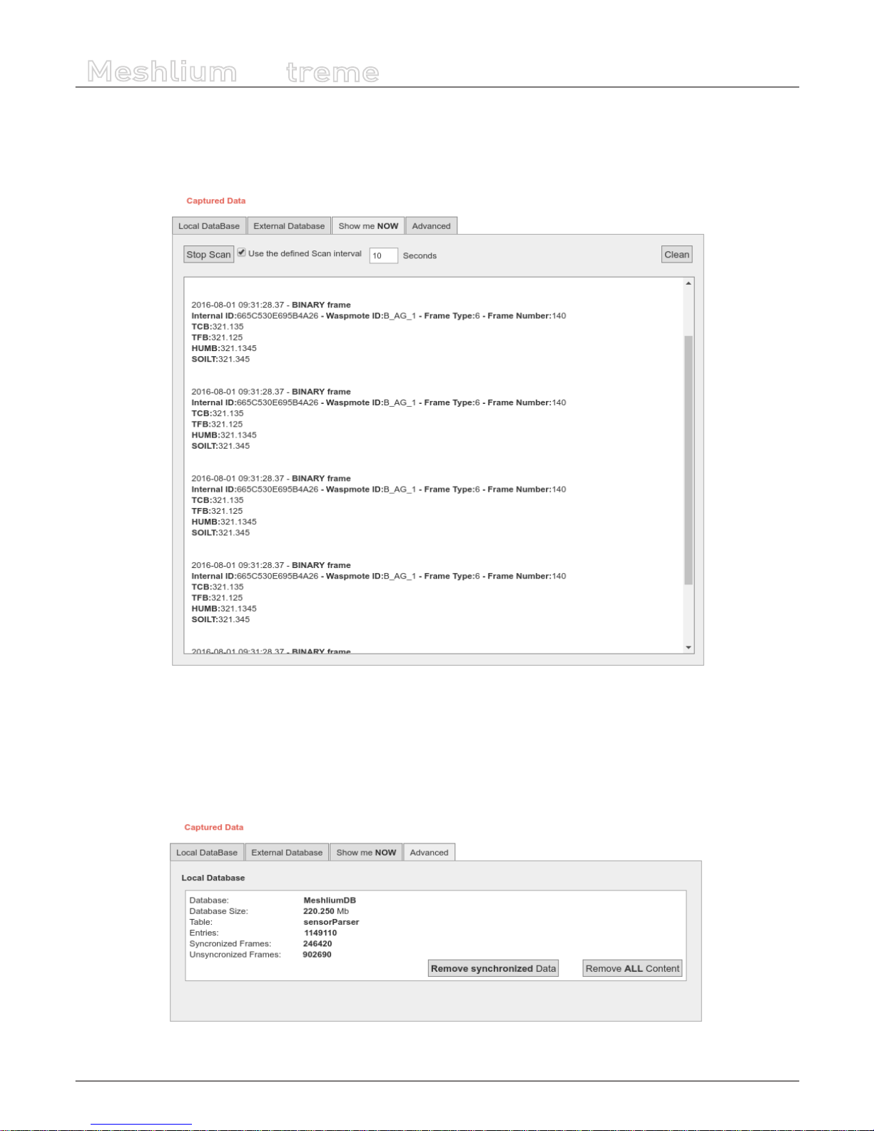
-55-
v7.1
Wireless Sensor Networks
Meshlium
X
treme
10.3.3. Show me Now
In this tab the user can show the last frame received. The user can show only last frame or can specify if the information will be
updated periodically with the dened interval just checking the “Use the Dened Interval” button.
Figure : Show me Now tab
The screen can be cleaned with the button in the top right.
10.3.4. Advanced database options
This tab shows information about local database.
Figure : Mark as synchronized button

-56-
v7.1
Wireless Sensor Networks
Meshlium
X
treme
It shows:
• Database name
• Database size
• Database table used
• Number of total sensor entries
• Number of frames already synchronized with external services
• Number of unsynchronized frames
There are too two controls to:
• Remove synchronized data. It removes from the database all the frames already synchronized with external database. Be
careful as this could give unexpected results if you are using several cloud or external services. A conrmation will be
prompted.
• Remove ALL content. This removes all the sensor information from the database. A conrmation will be prompted.
WARNING: The sensor data will permanently deleted from the database and will be impossible to recover. Be sure to have a backup
of the database before deleting the content.

-57-
v7.1
Wireless Sensor Networks
Meshlium
X
treme
10.4. Logs
In this section the user can see the last lines of the logs of frames and sensor data received.
Figure : Logs visualizing plugin
• The “Refresh” button will load again the log les
• The “Delete logs” button will delete the les, allowing to clean some space in the device
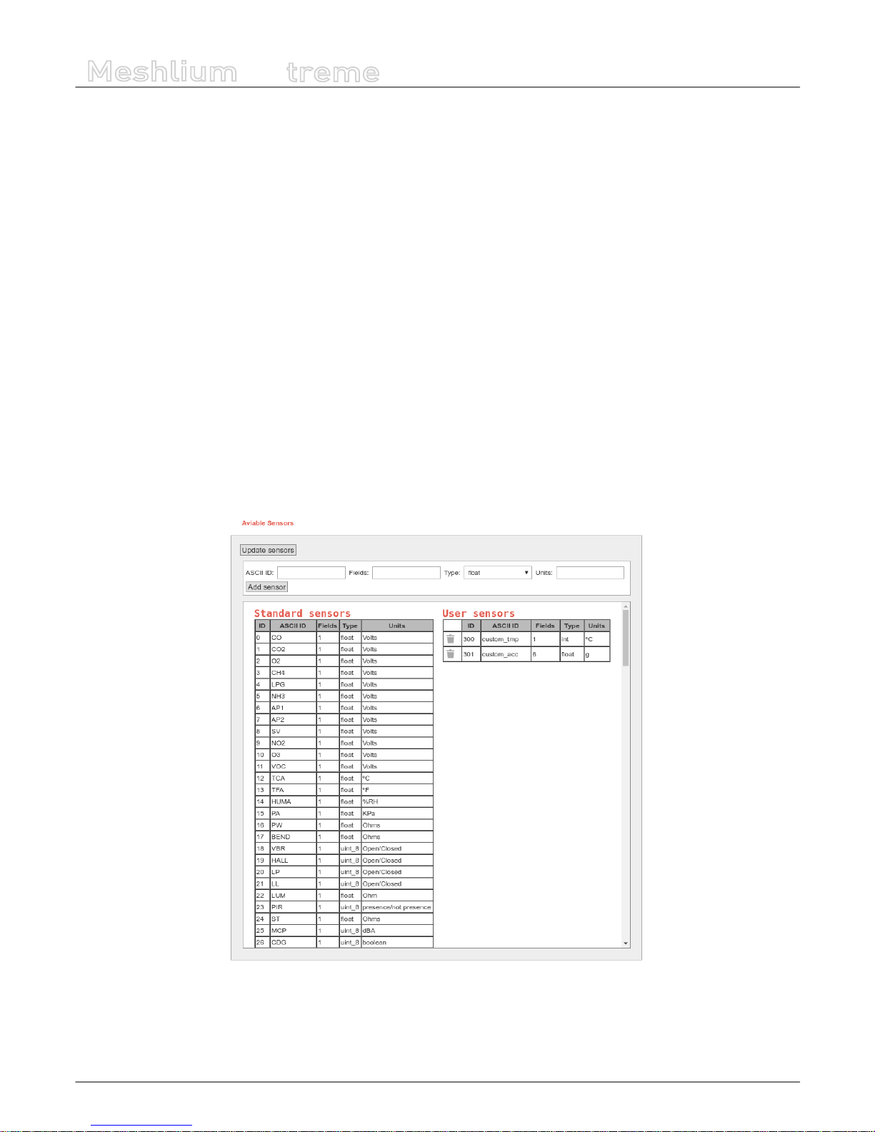
-58-
v7.1
Wireless Sensor Networks
Meshlium
X
treme
10.5. Sensor list
In this section, the user can view the list of available sensors in the system and add or delete user custom sensors.
By default, Meshlium recognize all Libelium ocial sensors frames. All sensor frames that Meshlium can capture and store
must be specied in an XML le. The button “update sensors” update the Libelium ocial sensor list. User sensors remaining
unchanged.
Users can add and remove custom sensors in an easy and simple way.
To add a new sensor the user must complete the elds:
• ASCII ID: sensor id for ASCII frame.
• Fields: This eld species the number of sensor elds sent in the frame. This helps to calculate the frame length.
• Type: type of elds:
- uint8_t
- int
- oat
- string
- ulong
- array (ulong)
• Units: Units for the sensor added.
Once all elds are lled in, click on the button “Add sensor”.
Figure : Sensor list plugin
Note: In “Waspmote data frame guide” document is located more extensive information about how to build the frame.
To delete sensor the user must press the garbage can that appears to the left of the description of the sensor. To complete the
action should accept a conrmation message.
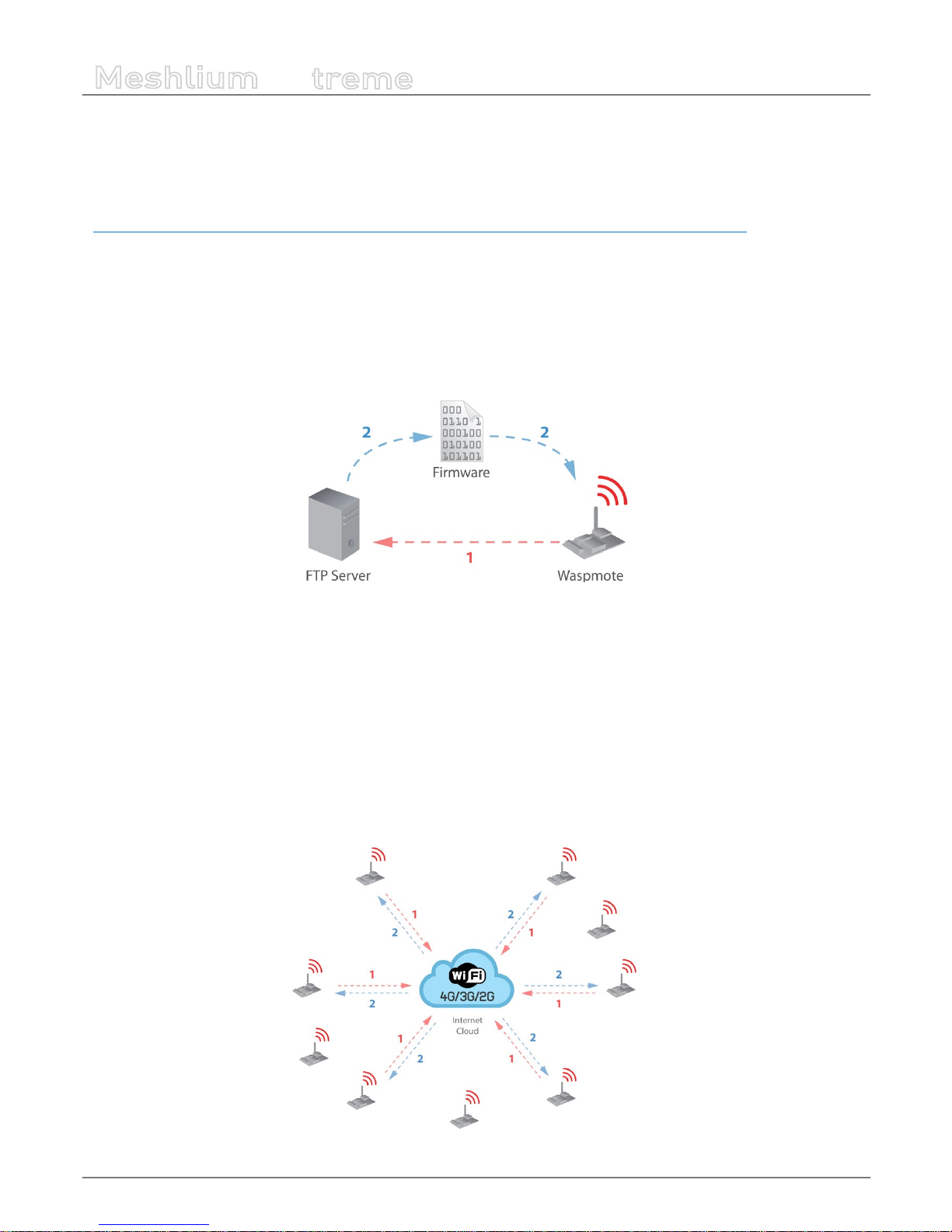
-59-
v7.1
Wireless Sensor Networks
Meshlium
X
treme
10.6. OTA via FTP
Meshlium can also be used as an FTP server to prepare the binary les to be downloaded by Waspmote.
For more info about Over the Air Programming go to:
http://www.libelium.com/development/waspmote/documentation/over-the-air-programming-guide-otap/
This feature allows reprogramming Waspmote using an FTP server (inside Meshlium) and FTP client (Waspmote itself).
There are two basic steps involved in OTA procedure:
• Step 1: Waspmote requests a special text le which gives information about the program to update: program name,
version, size, etc.
• Step 2: If the information given is correct, Waspmote queries the FTP server for a new program binary le and it updates its
ash memory in order to run the new program.
Figure : OTA via FTP protocol
Besides, a default user is congured in Meshlium FTP Server with the following settings:
• user: ota
• password: libelium
This user directly connects to the following path in Meshlium’s system directory where the application creates all the binary and
UPGRADE.TXT les:
/mnt/user/ota
Inside “Sensor Network” there is the section OTA - FTP. Users can prepare the binary les to be downloaded by Waspmote. Then,
the user can generate UPGRADE.TXT text le necessary to do OTA with 4G/3G/GPRS/GSM/WiFi via FTP.
Figure : OTA-FTP in Meshlium

-60-
v7.1
Wireless Sensor Networks
Meshlium
X
treme
Figure : OTA-FTP plugin
Firstly, there are three possibilities to be chosen:
• Select NO_FILE to inform Waspmote that no OTA is necessary
• Select a new le generated by the Waspmote platform IDE so as to update the Waspmote’s program.
• Select an existing binary if the user needs to update to an older program. The les are stored in the following path: /mnt/
user/ota.
Secondly, the program version is always set by the user before generating the new UPGRADE.TXT le. There is a specic input to
indicate the program version. It must be dened as a 1-unsigned-byte number (range: from 0 to 255).
Finally, there is a button to generate the new UPGRADE.TXT le.
Once these steps have been completed, the binary le and the proper UPGRADE.TXT le will be ready for the Waspmote devices
deployed which try to perform OTA via FTP transmission. This le is shown in the window of the application representing the
actual binary prepared for OTA.

-61-
v7.1
Meshlium Visualizer
Meshlium
X
treme
11. Meshlium Visualizer
Meshlium Visualizer is a plugin which plots graphs and maps with the data stored in the database. It can also export data in
common formats. Meshlium Visualizer is a special software feature only available in the Meshlium units included in the IoT
Vertical Kits (Smart Cities IoT Vertical Kit, Smart Water IoT Vertical Kit, etc).
Figure : Meshlium Visualizer can plot graphs and geo-locate data on maps
Please note that this is a paid service. In every IoT Vertical Kit, each Meshlium comes with 100 visualizations. After 100
visualizations, users can contact Libelium Sales Department (salesteam@libelium.com) if they want to continue using the
service.
11.1. Working with the Visualizer
On the top of the page you can use a simple form to make all your queries. To do so, just follow these steps:
Figure : Filling Meshlium Visualizer’s form
1.- Select one Plug & Sense! from the list. All Plug & Sense! units with frames in the database will be shown.
2.- Once a Plug & Sense! Is selected, all its sensors will be loaded. This process is repeated each time you change the selected
Plug & Sense!.
3.- Select the period of time you want to see in the chart. The “Live” option reads directly from the database, while the rest
options read from a le generated everyday by the service cron. For each Plug & Sense!, cron generates 4 les each day, one for
the last day, other for last 7 days, other for last 15 days and other for the last 30 days.
4.- Hit on the “Show Data” button and, if your query has results to show, Meshlium Visualizer will show them. The remaining
visualization number will decrease in one unit. If the query does not have any results, a message will appear notifying the
situation; the available visualizations remain without changes.
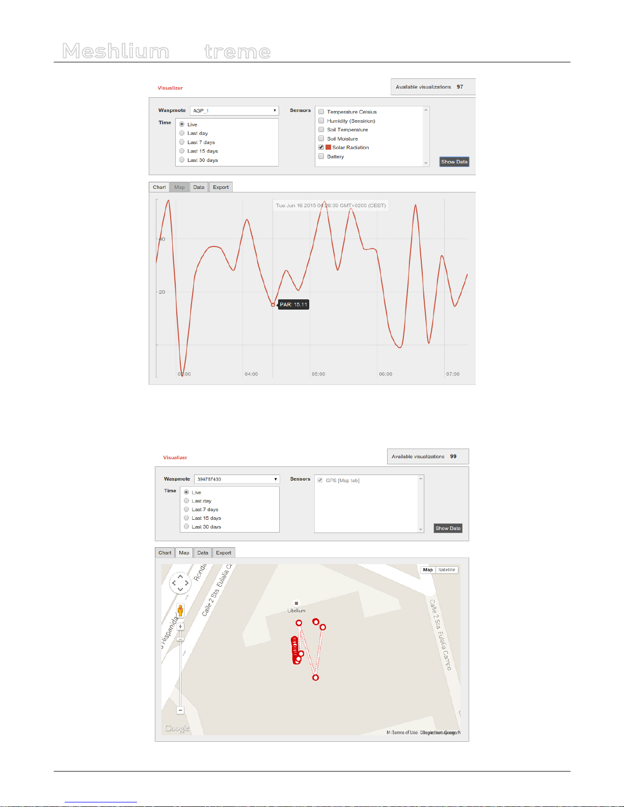
-62-
v7.1
Meshlium Visualizer
Meshlium
X
treme
Figure : Meshlium Visualizer showing one graph
If your query has GPS results (data frames with GPS information), the “Map” tab will be shown. If it is not the case, like in the
previous picture, this tab remains disabled.
Figure : Locating nodes on a map thanks to Meshlium Visualizer
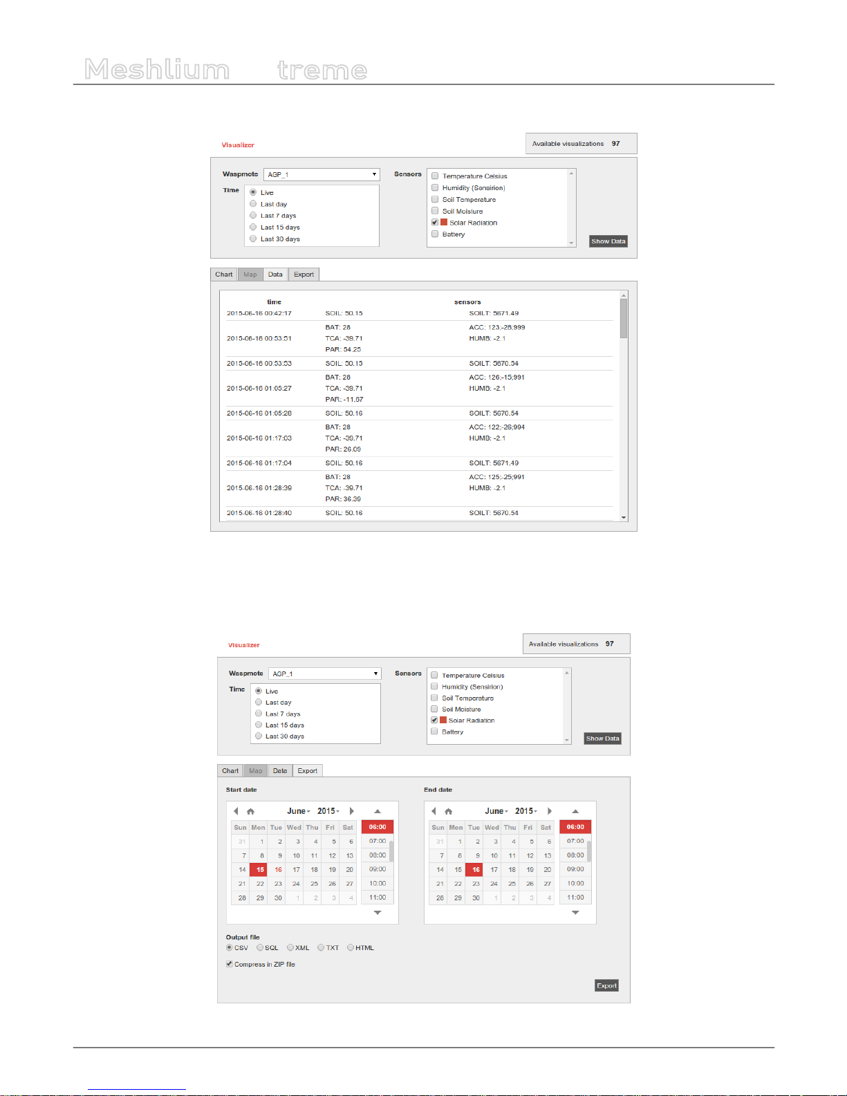
-63-
v7.1
Meshlium Visualizer
Meshlium
X
treme
The “Data” tab shows a list of sensor values, ordered by time.
Figure : Meshlium Visualizer showing the Data tab
The “Export” tab shows two calendars to select the initial and nal date. This feature does not take into account the block on the
top of the page, it will export all data from all Plug & Sense! units between these dates. Data can be exported in 5 formats (CSV,
SQL, XML, TXT & HTML) and compressed in ZIP.
Figure : Conguring Meshlium Visualizer to export data
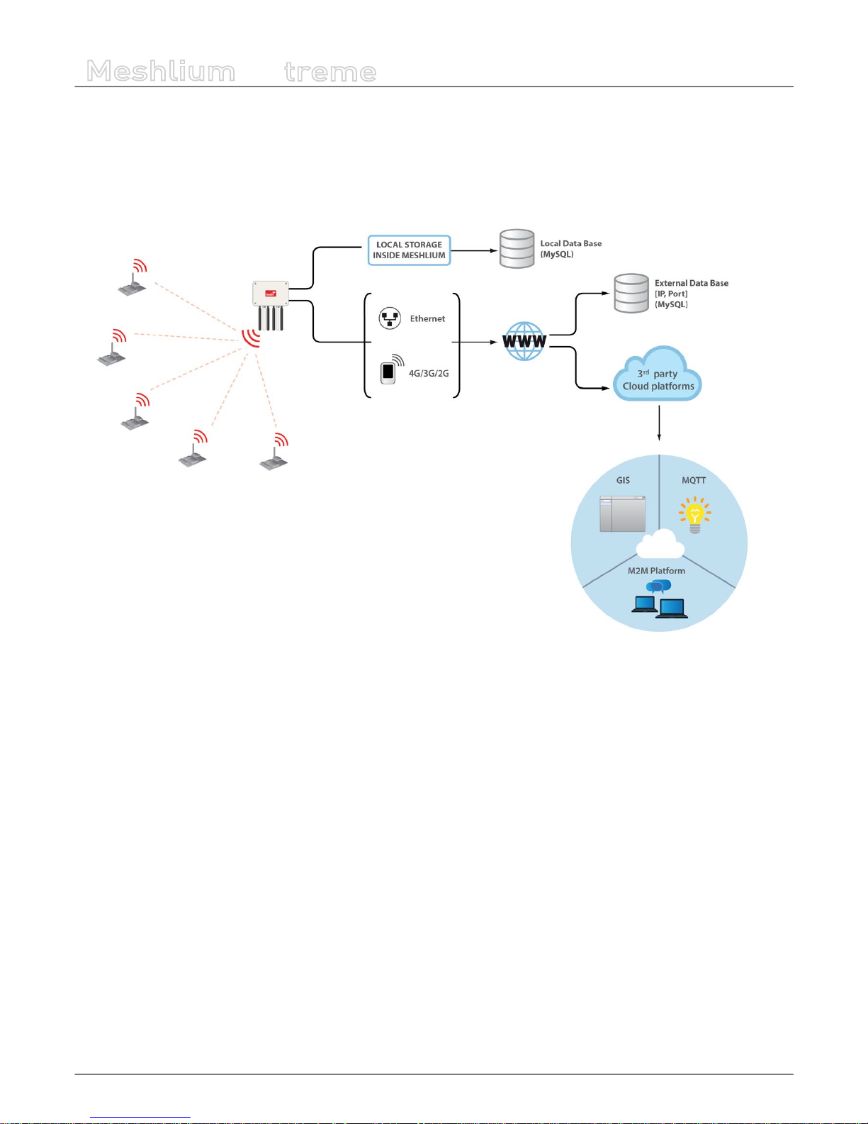
-64-
v7.1
Cloud Connectors
Meshlium
X
treme
12. Cloud Connectors
The aim of this chapter is to introduce the user to the Meshlium Cloud Connector functionality. This section will help you to
connect your Meshlium to a third party cloud platform.
Only sensor data can be sent to the cloud services.
Figure : Cloud connector diagram
Interfacing Meshlium with 3rd party cloud services should be the last step the user develops in any project. The user should
analyze if the use of clouds is needed, and if so, that will be the last step in the project. Before trying clouds, make sure all the
Waspmote units are sending frames to Meshlium, and Meshlium is receiving and inserting them on the local database properly.
What is a cloud platform?
Cloud computing is a major change in our industry. One of the most important parts of that paradigm are cloud platforms. This
kind of platforms let developers write applications that run in the cloud, use services provided from the cloud or both.
Meshlium Cloud Connector
Meshlium runs a set of scripts for implementing the data synchronization from its internal database “to the cloud”. In other
words, those scripts send data to webservers where the cloud service providers host their clouds. Those scripts are called Cloud
Connector.
We have divided the Cloud Connector into 2 groups: “IoT Solutions” and “IoT Platforms”.
IoT Platforms are professional development frameworks for developing data management applications, including Esri,
ThingWorx, IBM Bluemix, Telefónica and Microsoft Azure.
IoT Solutions are specic applications focused in dierent verticals. Libelium promotes the Cloud Partnership Program for any
cloud service provider that would like to foster their very own solution using our products.

-65-
v7.1
Cloud Connectors
Meshlium
X
treme
Figure : Cloud Connector main menu on the Manager System
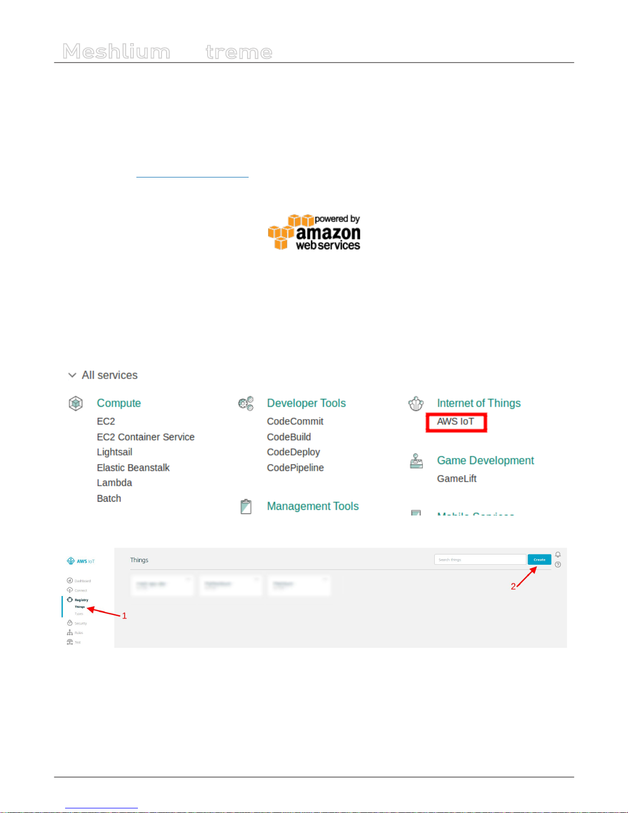
-66-
v7.1
Cloud Connectors
Meshlium
X
treme
12.1. IoT platforms
12.1.1. Amazon IoT
Amazon Web Services IoT enables secure, bi-directional communication between Internet-connected things (such as sensors,
actuators, embedded devices, or smart appliances) and the AWS cloud over MQTT and HTTP.
More information: http://aws.amazon.com/iot/.
With this plugin, Waspmote sensor data can be directly integrated with Amazon AWS IoT broker.
Figure : Amazon IoT plugin
12.1.1.1. Register Meshlium in Amazon IoT
To register Meshlium in Amazon IoT, you have to create a “thing” in your Amazon AWS IoT dashboard, attach a security certicate
and policy statement and copy the parameters to the plugin. Follow these steps to register your Meshlium:
1. Select AWS IoT in the Amazon Dashboard
2. Create a “Thing”

-67-
v7.1
Cloud Connectors
Meshlium
X
treme
3. Create a security certicate and download the les for later use
Figure : Save the credential les when connecting device

-68-
v7.1
Cloud Connectors
Meshlium
X
treme
4. Create and attach a policy
5. Copy the HTTPS connection string for later use
Figure : Annotate the value of the eld
It is important to annotate the conguration displayed and save the credential les when connecting the device. You will need
these les and parameters later for the Meshlium conguration.

-69-
v7.1
Cloud Connectors
Meshlium
X
treme
12.1.1.2. Conguration
You will use the previously obtained conguration from the AWS IoT platform to certicate your Meshlium as a valid sender of
MQTT messages.
Amazon IoT plugin is located in:
Manager System > Cloud Connector > IoT Platforms > Amazon Web Services
In the Conguration panel, the user can set:
• Public key: User public key le previously downloaded.
• Private key: User private key le previously downloaded.
• Certicate: Certicate le previously downloaded.
• Host: HTTPS connection string previously annotated.
• Port: AWS IoT MQTT port (by default 8883 for MQTT).
• ClientID: AWS IoT Client identication.
• Log Level: Generate log messages. From fewer to more details, the levels are: OFF, ERROR, INFO, DEBUG, REPORT. Default
is OFF.
• Topic template: Topic of your message. The user can use these wild-cards creating a personalized structure:
- #ID#: Unique identier for data
- #MESHLIUM#: Host name of the Meshlium unit
- #ID_WASP#: Identies the Waspmote unit
- #ID_SECRET#: Secret identier
- #SENSOR#: Identies the sensor
- #VALUE#: Value obtained from the sensor
- #TIMESTAMP#: MySQL TIMESTAMP type (‘YYYY-MM-DD HH:MM:SS’ UTC)
• Message template: Data structure of your message. The user can use these wild-cards creating a customized content:
- #ID#: Unique identier for data
- #MESHLIUM#: host name of the Meshlium
- #ID_WASP#: Identies the Waspmote unit
- #ID_SECRET#: Secret identier
- #SENSOR#: Identies the sensor
- #VALUE#: Value obtained from the sensor
- #TIMESTAMP#: MySQL TIMESTAMP type (‘YYYY-MM-DD HH:MM:SS’ UTC)

-70-
v7.1
Cloud Connectors
Meshlium
X
treme
Figure : Amazon IoT conguration panel

-71-
v7.1
Cloud Connectors
Meshlium
X
treme
12.1.1.3. Controlling synchronization
Once congured the server/broker, the user can launch the Meshlium Amazon IoT script (Start button). The program will search
for the received frames on the local database, and will send them to the Amazon IoT platform via MQTT protocol. The status
indicator displays the current state, saying “Running” or “Stopped”.
Figure : Amazon IoT sender is running
You can stop the Amazon IoT program anytime clicking on the “Stop” button.
Figure : Amazon IoT sender is stopped
12.1.2. Esri
ArcGIS is a complete spatial information platform provided by Esri, that allows to create, analyze, store and spread data, models,
maps and 3D globes. It can be accessed via desktop application, browser or handsets. ArcGIS is targeted at GIS professionals,
location analysts and developers that want to create their own applications based on geographical data.
More information: http://www.esri.com/products
Waspmote sensor data could be integrated into your existing maps and ArcGIS applications following the conguration steps
described for ArcGIS Online service.
12.1.2.1. ArcGIS Online
We can congure in this form all the parameters needed to connect and send data to the ArcGIS Online platform.
Figure : ArcGIS Online conguration
The parameters to setup are:
• esri_user: User for the Esri ArcGIS online platform.
• esri_password: Password for this Esri user.
• esri_service_name: Name of the service which will receive the data.
Clicking on the “Save” button, this setup is sent to the ArcGIS online service.
Clicking on the “Start” button enables the Esri Cloud Connector to send data periodically to the ArcGIS Online service previously
congured. A “running” status is displayed on screen showing that the Cloud Connector is sending data.

-72-
v7.1
Cloud Connectors
Meshlium
X
treme
Figure : ArcGIS Online “Start” button
Clicking on the “Stop” button will disable the Esri Cloud connector so Meshlium device stops feeding the ArcGIS Online service
with data.
Figure : ArcGIS Online “Stop” button
12.1.2.1.1. Check the Feature Server in ArcGIS Online
In order to check that data is arriving to ArcGIS Online, you should login in the platform:
https://www.arcgis.com/home/signin.html
Click on the option named “Gallery” and you should see a new Feature Server with the name that you provided in the Meshlium
conguration plugin:
Figure : ArcGIS Gallery
Opening the new content, you should see a map where each layer is one sensor type available in your project. Clicking on the
table icon, all the data collected for this type of sensor will be displayed.
Figure : ArcGIS sensor map view
At this point, it is possible to use this data to create new maps, collaborative apps or analytics making use of the complete array
of services provided by ArcGIS Online: https://developers.arcgis.com/en/.

-73-
v7.1
Cloud Connectors
Meshlium
X
treme
12.1.2.2. Devices
12.1.2.2.1. Meshlium
In the Meshlium section, the user can set and modify the name and description of the Meshlium.
Figure : Meshlium info in ArcGIS
12.1.2.2.2. Waspmotes
In the Waspmotes section, the user can manage the Waspmote units which are sending information to Meshlium.
Figure : Waspmotes list in ArcGIS
To add a new Waspmote, click on “Add new”. Then ll up this information:
• Name: The Waspmote name. Must match with the Waspmote identier used with the frame. See chapter “Capturing and
storing sensor data” for more information.
• Description: A description of that Waspmote unit.
• Sensor count: Number of sensors on that Waspmote. Must match with the number of elds of the frame. See chapter
“Capturing and storing sensor data” for more information.
And click on the “Add” button.
To modify a Waspmote, click on the Waspmote name for showing the attributes view.
Figure : Modify Waspmote in ArcGIS
Then the user can modify the name, description, and sensor count information. To save the properties, click on “Save”.
To delete this Waspmote unit, click on “Delete”.
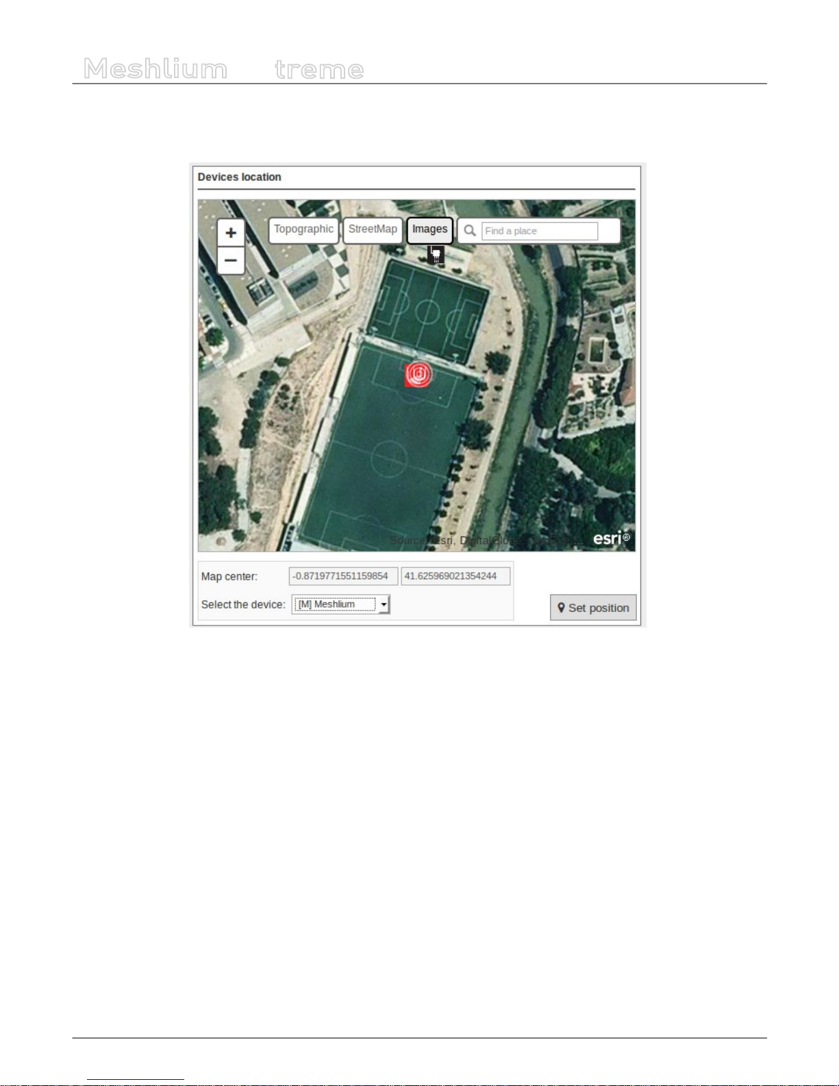
-74-
v7.1
Cloud Connectors
Meshlium
X
treme
12.1.2.2.3. Devices location
In the section Devices location, there is a viewer where the user can see Meshlium and Waspmote located on a map.
Figure : Devices location in ArcGIS
To change the location of the devices, center the map on the desired location, select the device, and click on “Set Position”.
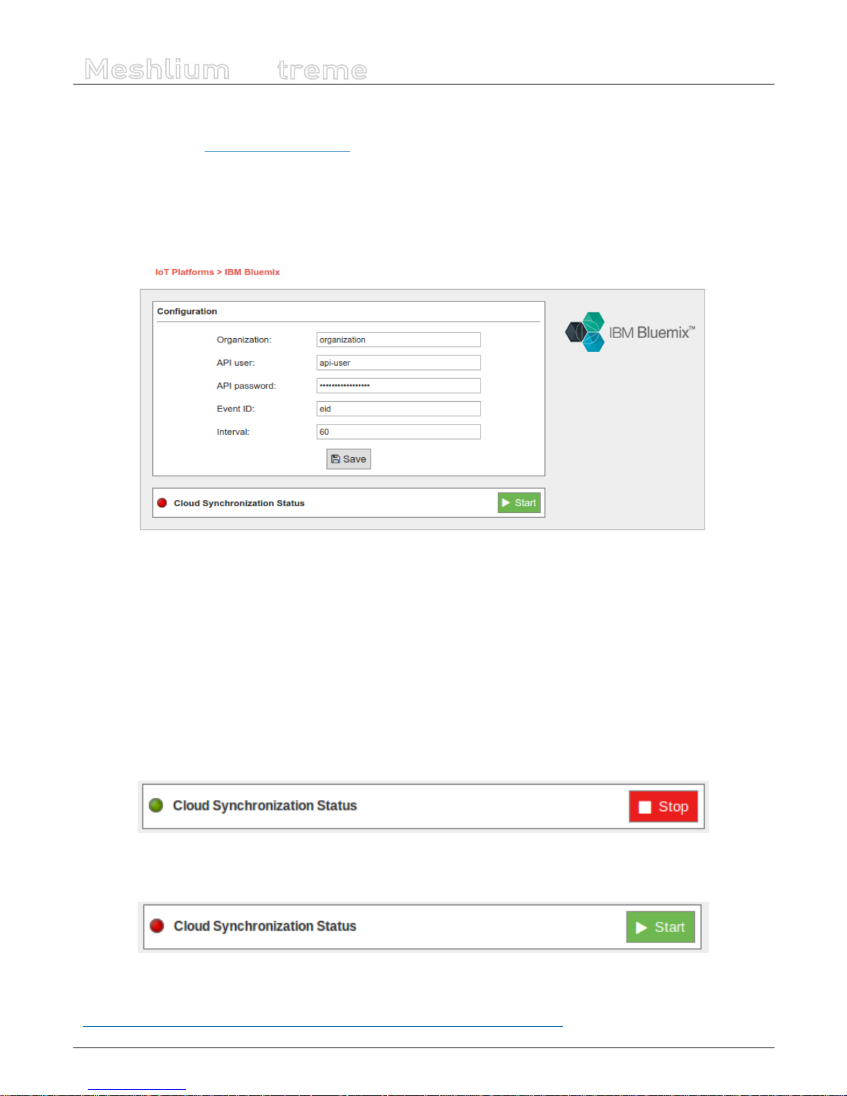
-75-
v7.1
Cloud Connectors
Meshlium
X
treme
12.1.3. IBM Bluemix
IBM Bluemix is a cloud platform as a service (PaaS) developed by IBM that gives a wide scope of services to use the cloud, one of
them is based on MQTT communications. This is a great alternative if the user do not want to build his own MQTT server.
12.1.3.1. Conguration
Conguration options are shown in the M2M Platform menu, enlarging the IBM Bluemix MQTT section. You will notice that the
conguration for this plugin is very straight-forward, you have most of the needed parameters on the IBM Bluemix web panel:
Figure : Conguring IBM Bluemix in Meshlium
• Organization ID: Identier of your organization; you can get it from the platform credentials.
• API user: User generated in the API platform section.
• API password: Password generated in the API platform section.
• Event ID: Used to congure the event where you want to send the information. If you do not know what to type in this eld,
you can use ‘eid’.
• Interval: Used to delay the communication after a bunch of messages were sent.
12.1.3.2. Controlling synchronization
You can stop or start the IBM Bluemix synchronization process anytime, hitting on the buttons “Start” and “Stop”. Then, the status
indicator displays the current state, saying “Running” or “Stopped”.
Figure : IBM Bluemix synchronization service is running
You can stop the synchronization anytime clicking on the “Stop” button.
Figure : BM Bluemix synchronization service is stopped
More information can be found on this Recipe we created for IBM:
https://developer.ibm.com/recipes/tutorials/bluemix-conguration-guide-for-meshlium/

-76-
v7.1
Cloud Connectors
Meshlium
X
treme
12.1.4. IoT-Ticket
IoT-Ticket is one of the world’s most complete, advanced and easy to use Industrial Internet of Things platforms with over 1.6
million users mainly in the energy and mobile machinery industry. Using IoT-Ticket you can build IoT applications in your webbrowser in minutes, no plug-ins required. You can create dashboards, reports, analytics or augmented reality based on big-data
collected from your things.
Figure : IoT-Ticket panel examples
Some benets oered by IoT-Ticket:
• Complete, up-to-date solution. IoT-Ticket is a complete remote management system which includes the electronics,
software and server. The platform is continuously developed further with new features and options.
• Easy to get started and integrated. You can use the platform as a service (SaaS or PaaS) or deploy to your own servers. We
can integrate IoT-Ticket with any of your other information systems.
• Flexibility and choice. Use the whole IoT-Ticket platform or part of it. Use IoT-Ticket specic electronics or use your own,
already deployed, electronics. Easy to use API in many programming languages allows a huge selection of devices to be
easily connected.
• Easy to use and Customizable. The IoT-Ticket web dashboards allows you to be up and running in minutes using only your
web browser. IoT-Ticket can be customized to meet your unique needs, even the look and feel can be made to match your
corporate brand identity.
More information can be found at www.iot-ticket.com.
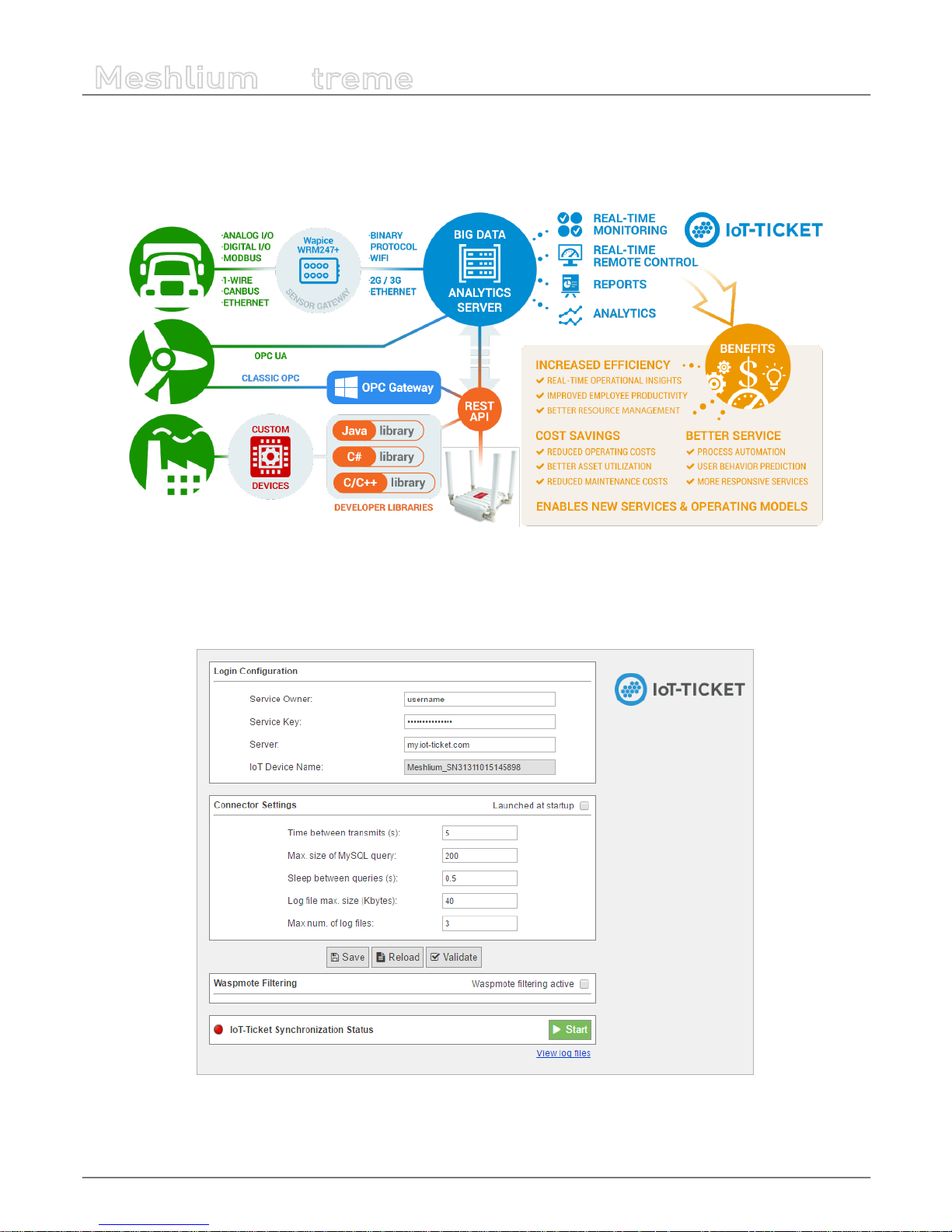
-77-
v7.1
Cloud Connectors
Meshlium
X
treme
12.1.4.1. IoT-Ticket Meshlium integration
Once Libelium’s Cloud Connector has been congured, all your available data will show up automatically in your IoT-Ticket webbased dashboard / report designer from where you can easily design Internet of Things applications.
Figure : IoT-Ticket Meshlium integration
The IoT-Ticket cloud connector settings can be found under the IoT section of the browser-based Meshlium Manager System.
The conguration is split into three parts Login Conguration, Connector Settings and Waspmote Filtering, as well as a section
for information about the current status of the connector with controls to start and stop the program.
Figure : IoT-Ticket plugin panel

-78-
v7.1
Cloud Connectors
Meshlium
X
treme
The Login Conguration section sets up the information for your IoT-Ticket account, and consists of four parts:
• Service Owner/Key gives the username and password of the my.iot-ticket.com service account to which you wish to
connect your Meshlium device.
• Server species the IoT-Ticket server to use, by default my.iot-ticket.com.
• IoT Device Name is a read-only eld showing the IoT-Ticket device name used for that Meshlium unit. It is set when the
connector is started and is empty if no name has yet been set (in such a case, use browser “Refresh” after connector has
started to see the name).
The Connector Settings section has parameters for the operation of the connector itself. These values aect time between
updates to IoT-Ticket as well as size of transmitted batches of data. More frequent data updates may come at the cost of
increased system resource usage.
• Launch at start. This checkbox indicates whether the connector is set to start automatically when the Meshlium is powered
on.
• Time between transmits gives the minimum elapsed time between transmissions to IoT-Ticket. Values less than 60
seconds may consume high system resources.
• Sleep between queries is the time the program sleeps between SQL queries, in order to conserve resources.
• Max. size of SQL query is the maximum number of results for a single SQL query to the Meshlium database. Values greater
than 200 may lead to high system load.
The section also allows for conguring connector logging:
• Log le max. size (kbytes). The maximum size of a single log le in kilobytes.
• Max. num. of log les is the number of log les that can be written before the logging handler begins overwriting the rst.
12.1.4.2. Save, load and verify
These buttons allow saving, loading and validating entered conguration data to a local le on the Meshlium disk which is read
by the connector. The saved data includes both the Login and Connector settings as well as any entered Waspmote ltering
rule (see “Waspmotes” section below).
Figure : Save, Load and Verify buttons
• Save validates the data entered into the form and saves to it to disk.
• Reload reads data back from disk, erasing any elds that have been changed since last save.
• Validate runs a check that entered elds are of the correct type and connects to IoT-Ticket to check the entered username
and password. If verication fails for a eld, it will be marked in red and an error message appears.

-79-
v7.1
Cloud Connectors
Meshlium
X
treme
12.1.4.3. Validation of settings
Conguration settings are validated to make sure the entered data elds make sense (e.g. numeric elds such as sleep and
query size must be numbers). Additionally, the validation will issue warnings if any parameters might cause high system load
on Meshlium.
Additionally the “Validate” button checks entered login information with the IoT-Ticket server and shows a warning if settings
are incorrect and a green conrmation message if they are correct.
Figure : Validation error
Figure : Validation success
12.1.4.4. Waspmote ltering
This section allows ltering of which Waspmote data is synchronized to IoT-Ticket. The section is enabled by ticking the
Waspmote ltering active checkbox.
Figure : Waspmotes list
• Refresh Waspmotes reloads the list of Waspmotes from the Meshlium database
• Select / Unselect All allows for quick selection or deselection of all present Waspmotes
The Waspmote infobox contains the following values:
• Name in the top-left shows the name a Waspmote broadcasts to the Meshlium with its readings (this is set in Waspmote
code). If not set, No name is displayed instead.
• Last Seen is the last date at which a sensor entry was sent from the Waspmote to the Meshlium.
• Sensors is a list of sensors present on that Waspmote device. Only the latest detected set is displayed here, in case sensors
are changed. Full names may be seen by hovering the mouse over the abbreviated names in the list.
• Include species whether the Waspmote should be included in the data transmitted by the connector. Deselected
Waspmotes have their info box greyed out.

-80-
v7.1
Cloud Connectors
Meshlium
X
treme
12.1.4.5. Synchronization status
This section allows the user to start and stop the connector and displays information about its current status. When the
connector is o, the indicator marker is red.
Figure : Start button
After clicking ”Start”, the connector shows a startup sequence, and when nished the running status will be indicated by the
status icon turning green. The start button becomes a red “Stop” button.
Figure : Stop button
The link “View log les” will allow you to see the status of the running connector via its log les. A ltered set of this logging data
will also be available as a data node in your IoT-Ticket enterprise.
12.1.4.6. IoT-Ticket view
Once the connector is running you can use your web browser to see the Meshlium data coming into your IoT-Ticket Dashboards
and Enterprise Manager on my.iot-ticket.com.
In your IoT-Ticket enterprise the Meshlium device will be viewable as an IoT-Ticket device under your enterprise and can now
easily be used in Enterprise Dashboards to create views of your incoming data, even mixing it with data coming from other IoT
sources.
Figure : IoT-Ticket panel

-81-
v7.1
Cloud Connectors
Meshlium
X
treme
You can now congure your own dashboard with sensor data and have it up and running in a matter of minutes.
Figure : IoT-Ticket panel
12.1.5. Microsoft Azure Event Hubs
Azure is a cloud platform provided by Microsoft. This platform has a lot of services to reach communication between machines
and devices.
This section focuses on Event Hubs, we can refer this technology as a way to send short messages via HTTP REST request. Event
Hubs is part of Service Bus. Event Hubs implements a simple message consumer M2M technology.
For more information about Event Hubs, see the following link:
https://azure.microsoft.com/en-us/services/event-hubs/
12.1.5.1. Setup in Azure - Creating NameSpace
Before getting the parameters to connect to Event Hub, it is necessary to create a Service Bus Namespace (skip this section if
you already have one).
Go to the Azure Event Hub Portal:
https://manage.windowsazure.com
Select the Service Bus menu. At the bottom of the Bus service manager screen you will see a NEW button with a plus image, click
on it. A pop-up window will appear where you must select message type “EVENT HUB”.

-82-
v7.1
Cloud Connectors
Meshlium
X
treme
Figure : Create new Namespace
12.1.5.2. Setup in Azure - Creating an Event Hub
In this section we will create an Event Hub that will receive our data from Meshlium. After we dive into the Service Bus we have
previously created, we can see a menu on the top of the screen, then we should choose “Event Hubs” and “Create a New Event
Hub”:
Figure : Create New Event Hub

-83-
v7.1
Cloud Connectors
Meshlium
X
treme
After clicking on this menu, a new screen will appear. At this point we can create a new event hub clicking on the bottom left
icon labeled as New:
Figure : Create a New Event Hub
After click this button, a pop-up window raises above and you are now able to create an event hub, we are going to choose
“quick create” option to make this step easier:
Figure : Quick Create
Type your event hub name and click “Create a new event hub” button to nish the conguration process.
Figure : Type the new Event Hub name

-84-
v7.1
Cloud Connectors
Meshlium
X
treme
You have created an Event hub for one day data retention, which means that your data will be kept one day.This method sets a
partition section with value ‘4’, which means the number of partitions the Event Hub may have.
12.1.5.3. Setup in Azure – Setting up shared access in Event Hub
We set up a shared directive to send data with custom credentials.Once we entered on event hub information (by clicking on
event hub), these credentials can be set up in the conguration section, this menu is on top of the screen:
Figure : Congure the Event
Click on the “congure” option and a new screen will be displayed. Here you can congure message retention, event hub
state, partition count and shared access policies. This last point (shared access policies) manages credentials to send and listen
messages (or both action), we will create a new credential to send messages. On “shared access policies”, type a name for your
key, and in the permissions drop-down menu, select “Manage” permission. Then press “save” on the bottom of the screen.
Figure : Congure the Event Permissions

-85-
v7.1
Cloud Connectors
Meshlium
X
treme
Finally, we will copy the information needed to connect the Event Hub connector. In order to do that, go to the “Dashboard” of
the Event Hub and select “View Connection String”.
Figure : Event Hub Dashboard
Copy the “Connection String” that appears in the screen.
Figure : Connection String

-86-
v7.1
Cloud Connectors
Meshlium
X
treme
We will extract the information needed to connect the Meshlium from the “Connection String”. You have to copy the NAMESPACE,
the DIRECTIVE_NAME, the DIRECTIVE_KEY and the EVENTHUB_NAME from the string as the following example:
Namespace=Endpoint=sb://NAMESPACE.servicebus.windows.net/;SharedAccessKeyName=DIRECTIVE_
NAME;SharedAccessKey=DIRECTIVE_KEY;EntityPath=EVENTHUB_NAME
Note that the namespace is only a part of the string Endpoint, it does NOT include the “sb://” neither the “.servicebus.windows.
net/” part.
12.1.5.4. Conguration
As result of previous steps, we should have a namespace, a directive name, a directive key and an event hub name. These are
the main properties we should set in the Manager System to congure an Event Hub connection.
Now we can access the Meshlium Manager and fulll the Azure Event Hub elds with the previously obtained conguration.
Figure : Conguring Azure Event Hubs in Meshlium
• Namespace: Name of the space created in the Azure service cloud.
• Directive name: Name of the directive created in Azure.
• Directive key: Key of the directive associated to the previous name.
• Name: Name of the Event Hub established in Azure.
• Template le: Users can dene their own data structure using these wild-cards (as you can see in the previous gure):
- #ID# : Unique identier for data
- #ID_WASP#: Identies the Waspmote unit
- #ID_SECRET#: Secret identier
- #SENSOR#: Identies the sensor
- #VALUE#: Value obtained from the sensor
#TS(“c”)#: Date with custom format. The parameter passed in this wild-card corresponds to the same ones you can use in PHP
date function (see format parameters in http://php.net/manual/es/function.date.php#refsect1-function.date-parameters).

-87-
v7.1
Cloud Connectors
Meshlium
X
treme
12.1.5.5. Controlling synchronization
Once you have saved the conguration, you can start sending your data via Event Hub to your Azure Cloud by pressing the
“Start” button. You will notice about it because the screen shows a spinning wheel when the process starts and displays a
“running” status.
Figure : Azure Event Hubs synchronization service is running
If you want to stop this process just press the “Stop” button. You can start/stop this process whenever you want.
Figure : Azure Event Hubs synchronization service is stopped
12.1.6. Microsoft Azure IoT Hub
Azure IoT Hub is a fully managed service that enables reliable and secure bi-directional communications between millions of
Internet of Things (IoT) devices and a solution back end. One of the biggest challenges that IoT projects face is how to reliably
and securely connect devices to the solution back end. To address this challenge, IoT Hub:
• Oers reliable device-to-cloud and cloud-to-device hyper-scale messaging.
• Enables secure communications using per-device security credentials and access control.
• Includes the most popular communication protocols.
More information: https://www.microsoft.com/en-us/cloud-platform/internet-of-things-azure-iot-suite.
With this plugin, Meshlium can send messages to your cloud back-end.
Figure : Azure IoT Hub plugin

-88-
v7.1
Cloud Connectors
Meshlium
X
treme
12.1.6.1. Register Meshlium in Azure Portal
To register Meshlium in Azure Portal, you have to follow the guide:
Get started with Azure IoT Hub for Java:
https://azure.microsoft.com/en-us/documentation/articles/iot-hub-java-java-getstarted/.
The guide explains how to create an IoT Hub and a device entity. It is important to annotate the connection string generated
after creating the device entity. You will need this parameter later for the Meshlium conguration.
In the Microsoft Azure Portal, go to IoT Hub menu and select:
Devices > myCreatedDevice > Shared access policies > iothubowner > Connection string – primary key
You have to annotate the value of this eld.
Figure : Annotate the value of the eld

-89-
v7.1
Cloud Connectors
Meshlium
X
treme
12.1.6.2. Conguration
You will use the previously obtained “connection string” from the Azure portal to certicate your Meshlium as a valid sender of
messages.
Microsoft Azure IoT Hub plugin is located in:
Manager System > Cloud Connector > IoT Platforms > Azure IoT Cloud
In the Conguration panel, the user can set:
• Connection String: Connection string previously copied.
• Number Requests: Number of requests to send per iteration.
• Protocol: Choose the protocol to communicate with Azure IoT Hub. Valid protocols are: MQTT (by default), AMQPS and
HTTPS.
Figure : Azure IoT Hub conguration panel
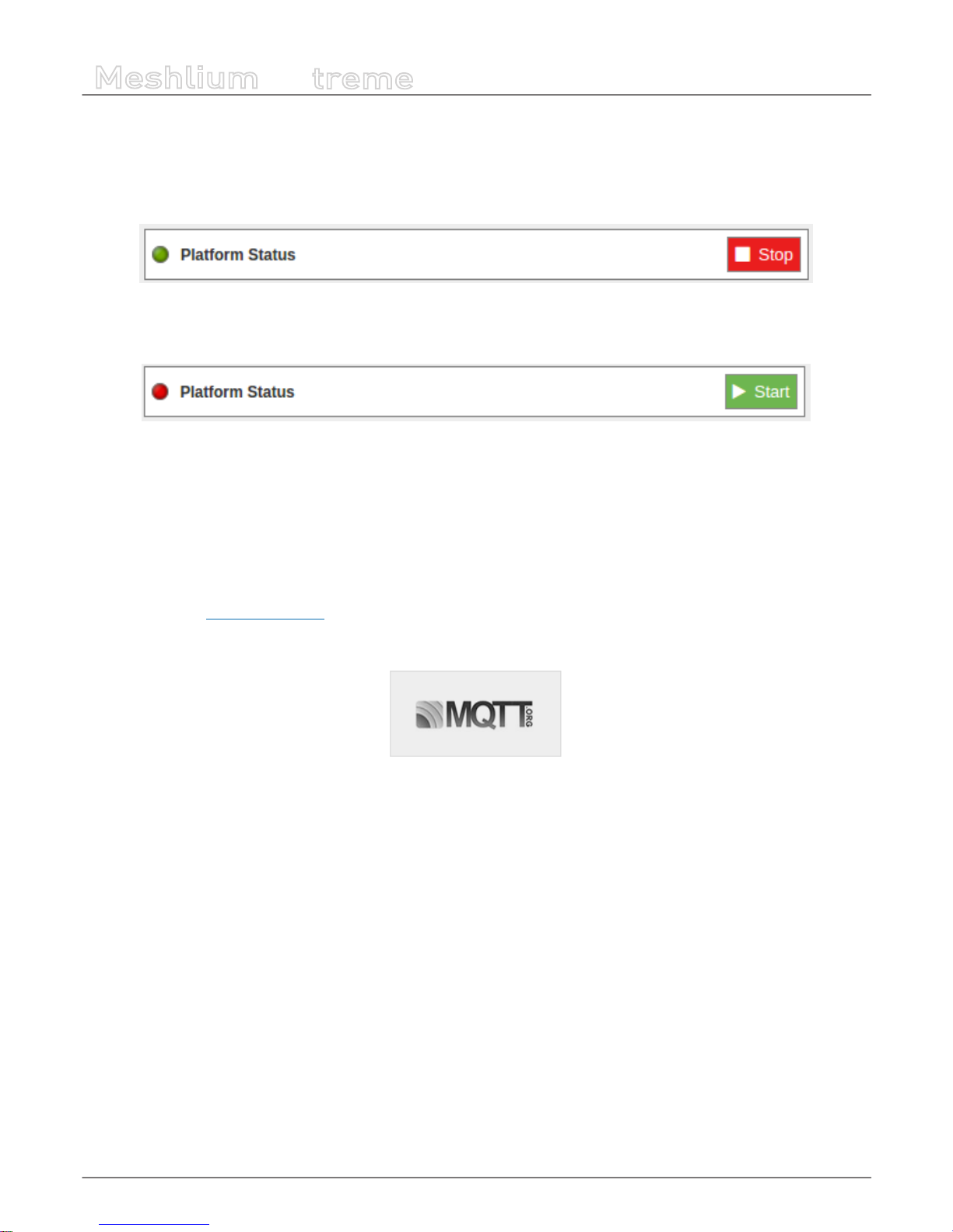
-90-
v7.1
Cloud Connectors
Meshlium
X
treme
12.1.6.3. Controlling synchronization
Once congured the server/broker, the user can launch the Meshlium Microsoft Azure IoT Hub script (Start button). The program
will send test messages to the Azure IoT Hub platform via the selected protocol. The status indicator displays the current state,
saying “Running” or “Stopped”.
Figure : Azure IoT Hub sender is running
You can stop the Azure IoT Hub program anytime clicking on the “Stop” button.
Figure : Azure IoT sender is stopped
12.1.7. MQTT
MQTT is a publish/subscribe, extremely simple and lightweight messaging protocol, designed by IBM for constrained devices
and low-bandwidth, high-latency or unreliable networks, where battery power is critical. Due to its features of delivery assurance
and bandwidth reduction, MQTT is being used by some Cloud platforms such as IBM or Carriots, which means that Waspmote
data can be stored inside them or in any other one based on this protocol.
More information: http://mqtt.org/faq.
With this plugin, Waspmote sensor data can be directly integrated with a MQTT broker.
Figure : MQTT plugin
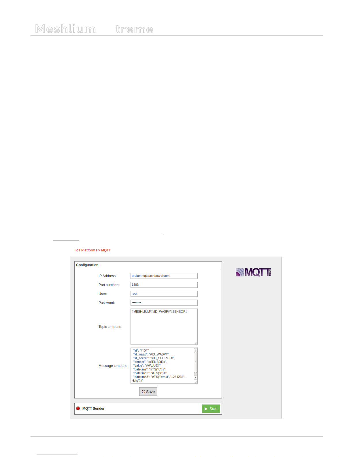
-91-
v7.1
Cloud Connectors
Meshlium
X
treme
12.1.7.1. Conguration
The broker is a key agent in MQTT protocol. The broker is a server which receives all the frames and distributes each one of them
to the subscribers clients.
MQTT plugin is located in:
Manager System > Cloud Connector > IoT Platforms > MQTT Solutions
In Server/Broker Conguration, the user can set:
• IP Address: Server IP address.
• Port number: Server port number.
• User: Server user name to log in the MQTT system.
• Password: Server password to log in the MQTT server.
• Topic template: Topic of your message. The user can use these wild-cards creating a personalized structure:
- #MESHLIUM#: Identier for Meshlium
- #ID#: Unique identier for data
- #ID_WASP#: Identier for Waspmote
- #SENSOR#: Sensor identication
• Message template: Data structure of your message. The user can use these wild-cards creating a customized content:
- #ID#: Unique identier for data
- #ID_WASP#: Identies the Waspmote unit
- #ID_SECRET#: Secret identier
- #SENSOR#: Identies the sensor
- #VALUE#: Value obtained from the sensor
- #TS(“c”)#: Date with custom format. The parameter passed in this wild-card corresponds to the same ones you can use
in PHP date function (see format parameters in http://php.net/manual/es/function.date.php#refsect1-function.date-
parameters).
Figure : Server/Broker Conguration

-92-
v7.1
Cloud Connectors
Meshlium
X
treme
Examples about MQTT Servers/Brokers:
• http://mqtt.org/wiki/doku.php/brokers
• http://mosquitto.org/
• http://mqtt.io/
Note: in this example, the broker was running on a computer inside our local network for test purposes only. For professional use, it is
recommended to work with a 24/7 server with static IP address.
12.1.7.2. Controlling status
Once congured the server/broker, the user can launch the Meshlium MQTT program (Start button). The program will search
for the received frames on the local database, and will send them to the broker via MQTT protocol. The status indicator displays
the current state, saying “Running” or “Stopped”.
Figure : MQTT sender is running
You can stop the MQTT sender anytime clicking on the “Stop” button.
Figure : MQTT sender is stopped
12.1.7.3. Platforms using MQTT
MQTT has been widely implemented across a variety of industries. As of March 2013, MQTT is in the process of undergoing
standardization at OASIS protocol stack. The protocol specication has been openly published with a royalty-free license for
many years, and companies such as Eurotech (formerly known as Arcom) have implemented the protocol in their products.
Here are a number of notable projects that have made use of MQTT and related technologies. Companies like Cisco, Eclipse
Foundation, Eurotech, IBM, Kaazing, M2Mi, Red Hat, Software AG, TIBCO and Carriots, among other companies, are working
with this protocol.
More information about examples and uses: http://mqtt.org/wiki/doku.php/example_uses.

-93-
v7.1
Cloud Connectors
Meshlium
X
treme
12.1.8. RIOT Platform
RIOT is a Sensing as a Service Platform developed by REDtone IOT. It manages connectivity from sensors or data sources with
various communication protocols including MQTT and RESTful.
Please visit http://riot.com.my/ for more information.
12.1.8.1. Conguration
Figure : RIOT plugin Conguration
The RIOT plugin is congured with the following parameters:
• URL: The IP address or the URL will be provided by REDtone IOT.
• API Key: An API Key will be provided by REDtone IOT as one of the authorization information in order to send data to the
RIOT platform.
• Gateway: Field to identify which Meshlium device the data came from when the platform receives the data, so that we can
trace the location.
Note: In the Waspmote sensor board, make sure you identify each board with their own ID so that we can trace which sensor board
the data originated.
12.1.8.2. Controlling synchronization
The synchronization will be executed for all the data that has not been synchronized in the Sensor Parser database table. You
can start and stop the synchronization process. In the interface of our service, you can see if the status of our service is either
running or not. If you click on “Start”, the synchronization will start.
Figure : RIOT sender is running
If you want to stop the synchronization process, you can simply just click on “Stop” and the process will stop.
Figure : RIOT sender is stopped
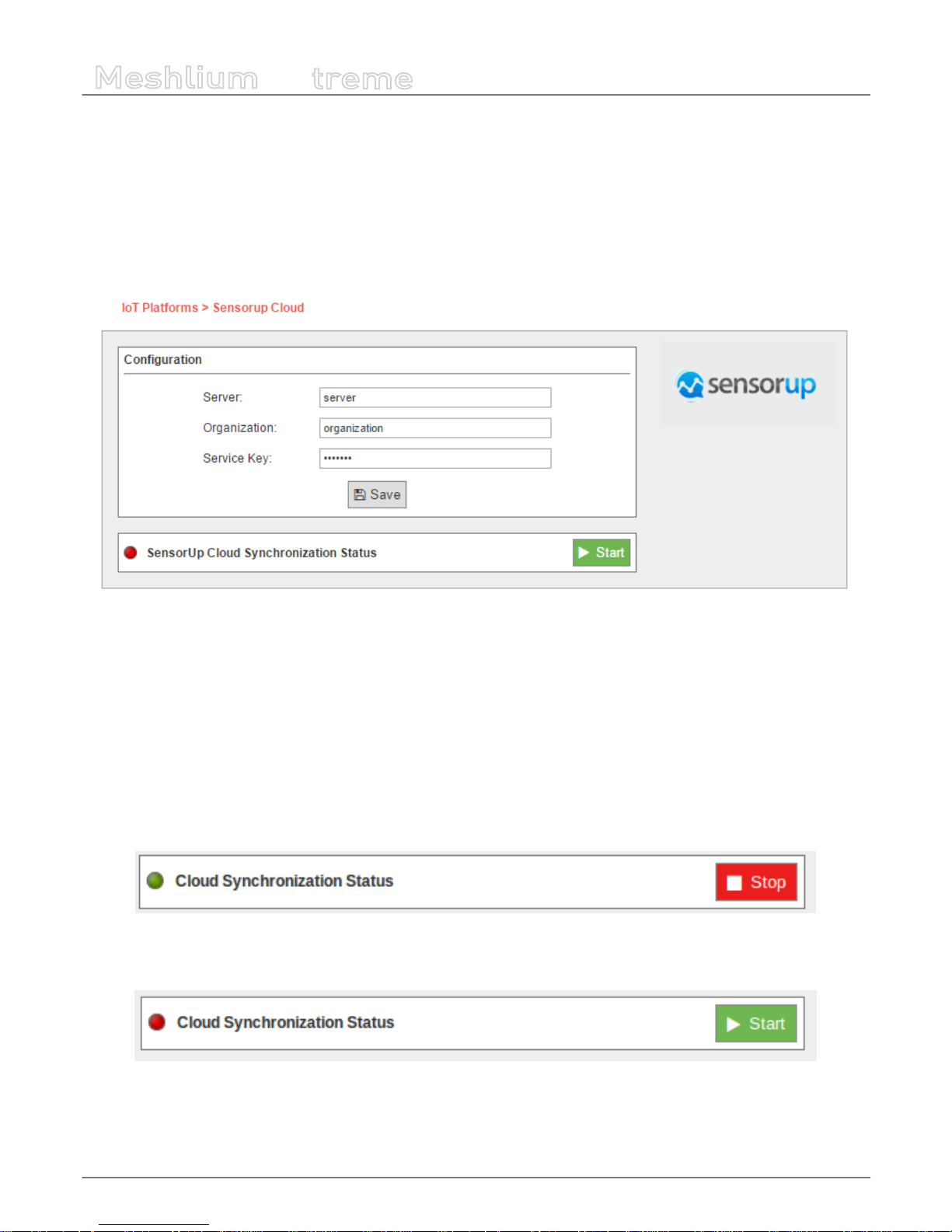
-94-
v7.1
Cloud Connectors
Meshlium
X
treme
12.1.9. SensorUp IoT Platform
SensorUp provides an open standard IoT platform that enables information from all dierent kinds of sensors accessible in a
single platform.
12.1.9.1. Conguration
You can access the SensorUp IoT platform plugin from the Cloud Connector menu, and setup all the information needed to
connect Meshlium to the SensorUp IoT platform.
Figure : SensorUp conguring plugin
• Server: SensorUp IoT platform server
• Organization: Identier of your organization
• Service Key: Key used to access SensorUp IoT platform
All these parameters are provided by SensorUp.
12.1.9.2. Controlling synchronization
Once you have saved the conguration, you can send your data to the SensorUp IoT platform by pressing the “Start” button. You
will notice about it because the screen shows a spinning wheel when the process starts and displays a “running” status.
Figure : SensorUp status “Running”
If you want to stop this process, just press the “Stop” button. You can start/stop this process anytime.
Figure : SensorUp status “Stopped”
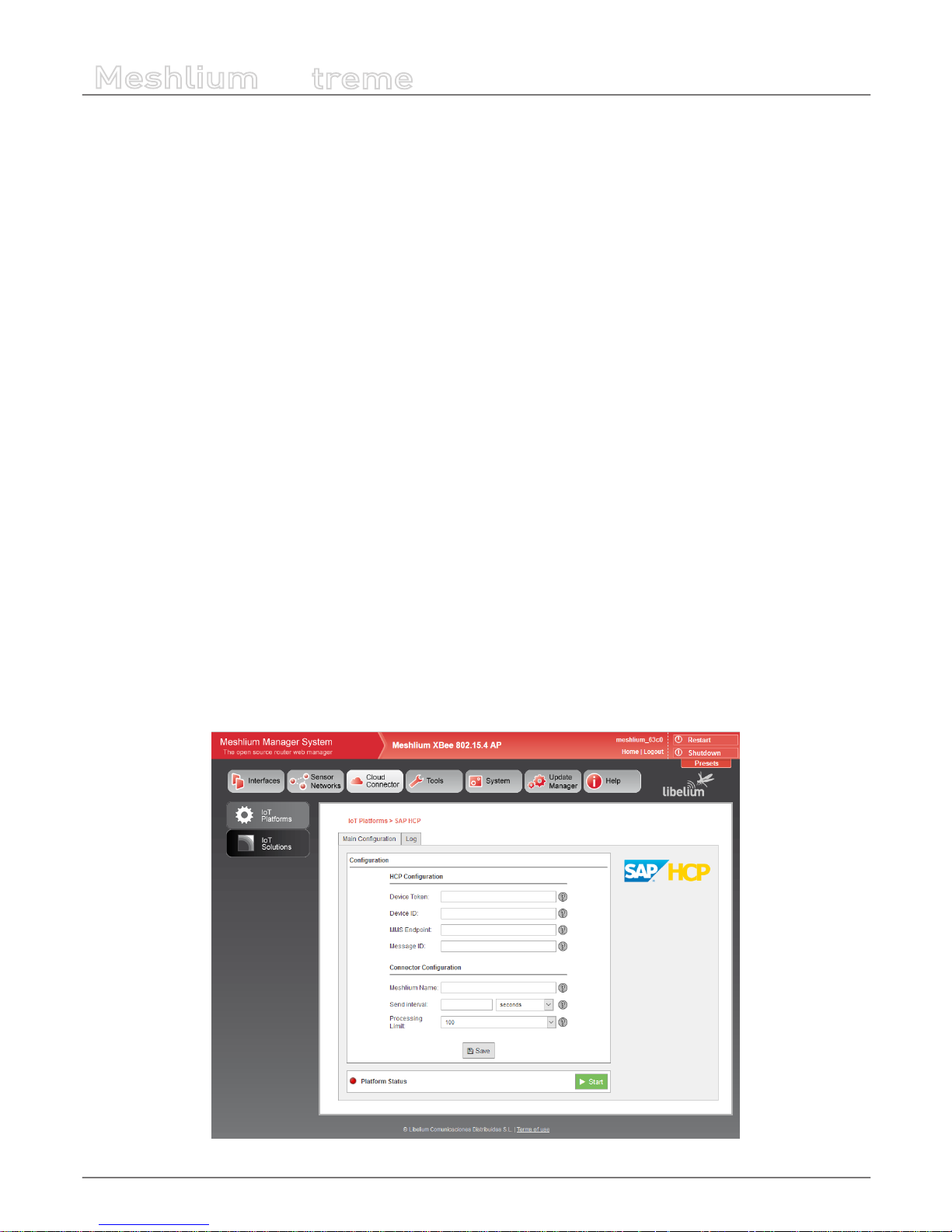
-95-
v7.1
Cloud Connectors
Meshlium
X
treme
12.1.10. TechEdge SAP HANA
SAP HANA Cloud Platform is a platform-as-a-service open (PaaS) that provides unique services for databases and applications in
memory. It is the cloud platform that allows you to quickly develop new applications or extend existing ones. Allowing anyone
to extend SAP applications within minutes, all in the cloud.
With SAP HANA Cloud Platform you can:
• Deploy in the cloud and their existing on-premise applications. You can quickly add a new functionality to their existing
applications in the cloud and on-premise.
• Connect your cloud and on-premise applications to eliminate data silos and make a simple, secure and scalable digital
access
• Create and run new applications in the cloud to solve new problems, make new customers and new income
• It allows to connect the business processes with eld devices through Internet of things (IoT) services.
This platform allows:
• Enable remote services management of devices
• Communicate through secure protocols with eld devices
• Manage devices and their messages remotely through programming interfaces (API)
12.1.10.1. Conguring SAP HANA
To make the connection between the platform and the SAP HCP Gateway Meshlium by Libelium, so we can receive the data sent
from the gateway, a pre-conguration of Things Internet service is required.
For more information about how to congure the Things Internet service, please contact your TechEdge contact.
12.1.10.2. Conguration
Select the “IoT Platforms” and press on SAP HCP to access the service conguration screen of TechEdge cloud connector for SAP
HANA Cloud Platform.
By accessing the SAP HCP connector conguration screen, a form with the necessary elds to congure is displayed.
Figure : TechEdge conguration plugin

-96-
v7.1
Cloud Connectors
Meshlium
X
treme
• Device Token: The Token OAuth2.0 provided by HCP to the device create (you must congure SAP HCP IoT before, as
described in the previous sections)
• Device ID: Identier of the device created in HCP
• MMS Endpoint: Data Endpoint of HCP MMS services
• Message ID: ID of message type created in HCP
• Meshlium Name: Meshlium unit identifying name (free eld)
• Send Interval: Denes the connector’s space of time to wait between each HCP cloud deliveries. Each delivery contains
between 100 and 200 sensors traces, and in order to not saturating the Gateway memory, the minimum accepted is 5
seconds.
• Processing Limit: Limit of simultaneous messages processing in each of HCP cloud deliveries, the gures are considered
between 100 and 200, these are the gures recommended by Libelium to ensure a high performance in the Gateway.
After setting all elds described above, it is necessary to save the changes by clicking the “Save” button at the bottom of the
conguration form.
12.1.10.3. Controlling synchronization
After saving the conguration, you can now start the service. To do this click on the “Start” button.
Figure : TechEdge status “Running”
When the service has started, “Platform Status” is displayed in green, and the “Start” button changes to “Stop”.
Note: The Data synchronization with Meshlium will be held as maximum packet size dened in “Processing Limit” eld. All those
new data received since the last delivery will be synchronized, if the data exceeds the maximum size set to “Processing Limit” several
deliveries will be made to complete the synchronization.
With the service has started, to stop the service you must click on the “Stop” button on the HCP conguration screen in Meshlium.
Figure : TechEdge status “Stopped”
Pressing the “Stop” button, a stop will start in a controlled manner, allowing you to stop the service without incident (close les,
ends active processes of polling, etc.), ensuring a proper functioning of the Meshlium gateway
When the service has stopped, “Platform Status” is displayed in red, and the “Stop” button will change by “Start”.

-97-
v7.1
Cloud Connectors
Meshlium
X
treme
12.1.11. Telefónica IoT Platform
Telefónica provides an M2M cloud to collect and analyze data. This platform is based on assets and models and you can optimize
your business processes implementing rules and notications, and subscribing to data from dierent hosts.
12.1.11.1. Conguration
A new option is shown in M2M Platform menu, in the Cloud Connector main option. If you expand it, you can see this form with
3 elds in it:
Figure : Telefónica IoT setup example on Manager System
• URL: Address of the API service of Telefónica IoT. This address should be provided without the “http://”, usually int.dca.tid.es.
• Port: The port in which the API listens to connections.
• API: The security key to send data to Telefónica IoT.
All this data are provided by Telefónica service administrators.
12.1.11.2. Controlling synchronization
The synchronization will be done in packs of 100 data at a time, so the system is not overloaded. You can start and stop the data
synchronization to the Telefónica service. In the interface, you can see an indicator of whether the Telefónica service is running
or not. If you click on “Start”, the synchronization will begin:
Figure : Telefónica IoT Start button
You can stop at any moment clicking on “Stop” button.
Figure : Telefónica IoT Stop button

-98-
v7.1
Cloud Connectors
Meshlium
X
treme
12.1.12. Telit
The Meshlium Cloud Connector for the Telit deviceWISE IoT Cloud platform is provided to connect Libelium Waspmote sensor
devices to the Telit Cloud Platform.
12.1.12.1. Register in Telit
The basic steps required to connect Waspmote sensors to the cloud platform are simple and straight forward:
A) Using the Telit Management Portal at portal.telit.com
• Create/Obtain a Telit IoT Portal Account on a Cloud Organization
• Dene 2 Thing Denitions:
- Meshlium Cloud Connector
- Waspmote Sensor
• Create an Application Token for the Meshlium Cloud Connector Denition
B) Using the Meshlium Manager System web browser interface
• Access the Telit deviceWISE TR-50 Cloud Platform Conguration Panel
• Enter and Save the conguration details for your Meshlium including the Application Token created above
• Start the deviceWISE TR-50 Sensor Processing Service
Once your Telit IoT Cloud account has been congured with the new ‘Thing Denitions’ and ‘Application’ in support of the
Meshlium Cloud Connector, you are ready to proceed with conguring your Meshlium gateway.
12.1.12.2. Conguration
Select the ‘Telit deviceWISE Cloud Connector’ service icon located on the ‘IoT Platforms’ panel. Congure the elds to provide the
required conguration and control information on the ‘Telit deviceWISE Cloud Connector’ management panel as shown below.
Figure : Telit conguration panel

-99-
v7.1
Cloud Connectors
Meshlium
X
treme
Figure : Telit conguration options
Where:
• ‘Cloud Server URL’ species the target Telit IoT Cloud Platform.
• ‘Meshlium Id’ indicates the unique name that you would like your Meshlium Gateway to be known as in the Telit IoT Cloud
Platform.
• ‘Application Token’ indicates the unique secure token generated by the Telit IoT Cloud Platform for devices to be able to
access your private cloud organization.
• ‘Process Frequency’ indicates how often the cloud connector should check for and process newly received data frames from
the associated Waspmote/Edge devices. Valid values range from 30 to 120 seconds.
• ‘Process Limit’ species the maximum number of waiting records to process during the data frame processing cycle. Valid
values range from 8 to 200.
Once all settings are provided, save the conguration settings by pressing the Save button.
Figure : Save conguration error
In the event that a eld has been left blank or a string has been entered into a numeric data eld, the eld entry frame will be
highlighted and an error message will be displayed as shown in the screen images below.
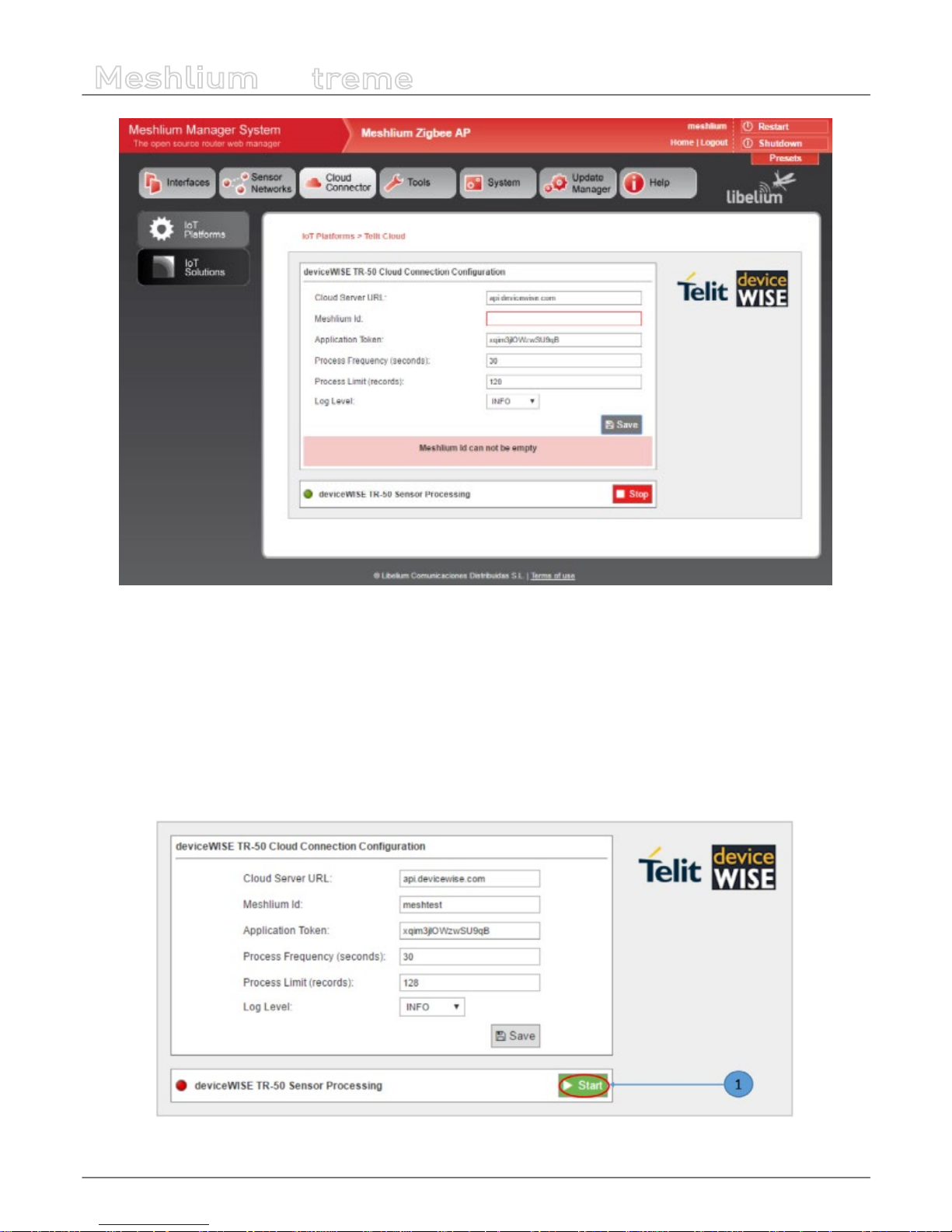
-100-
v7.1
Cloud Connectors
Meshlium
X
treme
Figure : Save conguration button
At this point the Meshlium Cloud Connector is congured and ready to start.
12.1.12.3. Controlling synchronization
Once the Telit deviceWISE IoT Cloud Connector has been congured with the proper runtime parameters, it is ready for operation.
To initiate the connection from the Meshlium gateway to the Telit IoT Cloud Platform and start the background service awaiting
data frames from Waspmote sensor device nodes, press the Start button.
To initiate the connection from the Meshlium gateway to the Telit IoT Cloud Platform and start the background service awaiting
data frames from Waspmote sensor device nodes, press the Start button.
Figure : Telit Start button
 Loading...