

Page 1
Adeunis
Field Test Device Guide
Page 2

Index
Document version: v7.0- 01/2019
© Libelium Comunicaciones Distribuidas S.L.
INDEX
1. Basic information .................................................................................................................3
2. Device description ................................................................................................................4
2.1. User interface .................................................................................................................................... 4
2.2. Interface description......................................................................................................................... 5
2.3. Screen description ............................................................................................................................ 6
2.3.1. Start screen ............................................................................................................................6
2.3.2. Join screen ..............................................................................................................................7
2.3.3. Uplink/downlink screen ........................................................................................................8
2.3.4. GPS screen .............................................................................................................................9
2.3.5. PER (Packet Error Rate) screen ............................................................................................9
2.3.6. Downlink screen ..................................................................................................................10
3. Working mode ..................................................................................................................... 11
3.1. Enroll the device on the Loriot backend ...................................................................................... 11
3.2. Testing the device ........................................................................................................................... 13
3.3. Universal Ranger application ......................................................................................................... 15
3.4. General recommendations ............................................................................................................ 16
-2- v7.0
Page 3
Basic information
1. Basic information
Important:
The Field Test Device (FTD) by Adeunis is a Class A & C LoRaWAN compatible device. This is not a point-to-point
device and may not be used in this manner. This indicates that it must be used on a private or public operated
network.
The Field Test Device is a ready-to-use device, which makes it possible to communicate with all network operators
using the LoRaWAN V1.0 protocol. The system makes it possible to transmit and receive radio frames and to
instantly view the results.
Equipped with a large LCD screen, the user can view various information relating to how the network being used is
functioning (Uplink, Downlink, SF, PER, etc) in addition to information from sensors (GPS coordinates, temperature,
battery level, etc). This device is specically adapted for application validation, such as communicating sensors,
tracking, smart building, metering, security and M2M.
So the main purpose of the Field Test Device is to help the user to nd good deployment sites for LoRaWAN end-
nodes (or even base stations). The user will be able to make informed decisions: installing a node on a lamppost
or the next one can mean a dierence of many dBm, and thus, having or not a stable RF link.
Thanks to its rechargeable battery, the FTD allows several hours of functioning and can be recharged using a
standard mobile phone micro-USB.
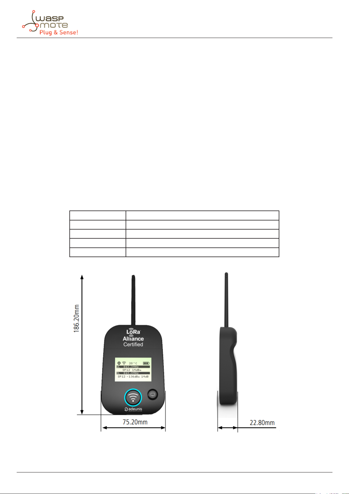
Dimensions 186.2 x 75.2 x 22.8 mm
Weight 140 g
Materials Unit: ABS
Lexan: Autotex Polycarbonate
Antenna: Thermolast K TC7AA
Figure: Adeunis Field Test Device
-3- v7.0
Page 4
2. Device description
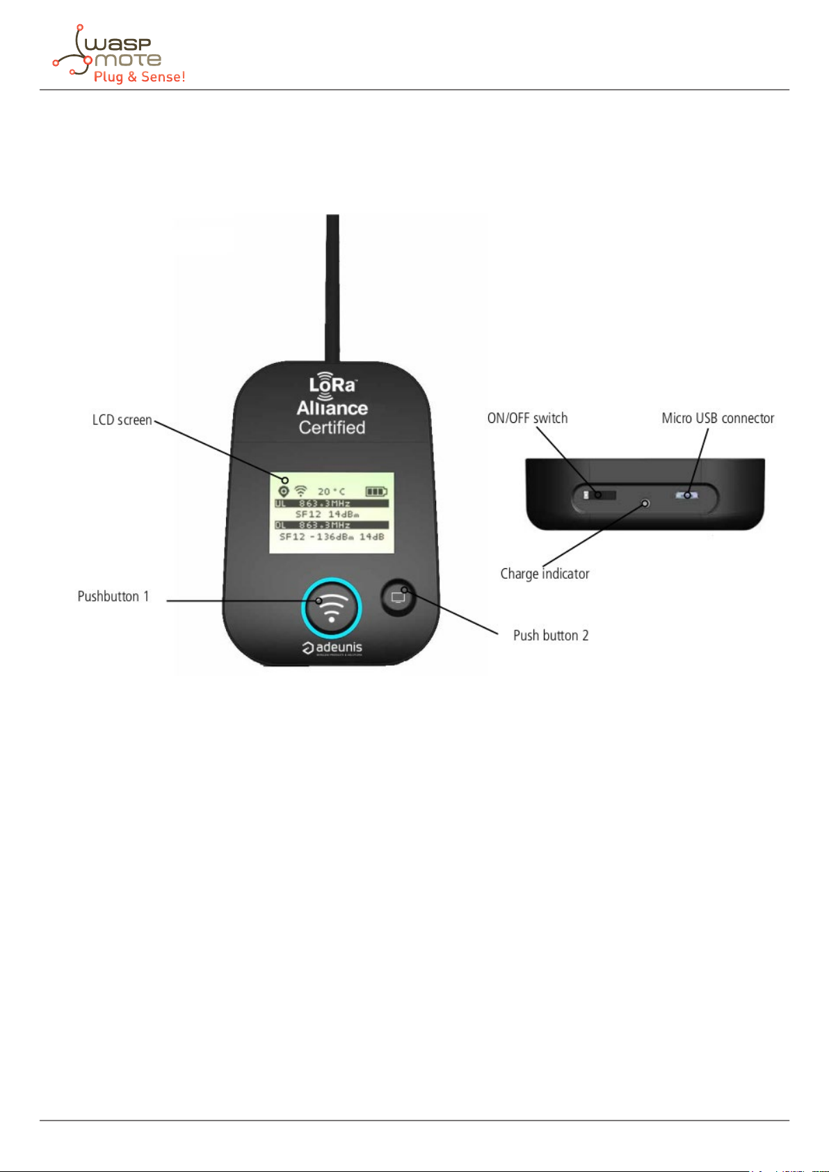
2.1. User interface
Device description
Figure: FTD interface
-4- v7.0
Page 5
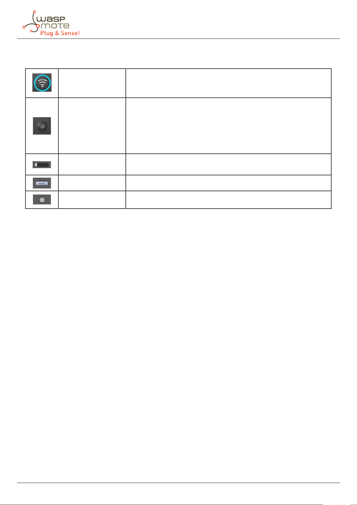
2.2. Interface description
This button allows you to carry out radio transmissions in manual mode.
Push button 1
Push button 2
In the PER menu, a long press will allow you to reset the counters to zero.
This button allows you to manage the LCD screen.
When the LCD backlight is switched o, pressing this button will switch
on the backlight.
When the LCD backlight is switched on, each press will allow you to scroll
through the dierent screens available on this device.
Device description
On/o switch
Micro-USB connector
Charge indicator
The Adeunis Field Test Device also has 2 on-board sensors: a temperature sensor and an accelerometer. The
accelerometer triggers a send a frame when a large vibration is detected (by shaking the device for example).
The on/o switch allows you to switch the device on or o. Moving the
switch to the right will turn the device on.
The micro-USB connector allows you to charge the device.
The charge LED shows you the device’s charge status.
-5- v7.0
Page 6

2.3. Screen description
The LCD screen of the product is split on few parts:
• The “Start” screen (it shows the rmware version) - Only on the powering up process
• The “Join” screen - Only on the powering up and after a command mode exit
• The “Uplink/downlink” screen (main screen)
• The “GPS” screen
• The “PER” screen (Packet Error Rate)
• The “Downlink frame” screen
The following icons are present on each screen of the product:
Item Icon Description
No icon GPS has been deactivated
GPS status
Temperature Temperature in °C
Battery
GPS has not been synchronized
GPS has been synchronized
Battery level
Product in charge
Device description
2.3.1. Start screen
The device is switched on using the on/o switch located on the underside of the device. Once it has been switched
on, the device’s LCD screen will light up and the start menu will be displayed. This screen shows the 2 rmware
versions during few seconds.
Figure: Start screen
-6- v7.0
Page 7

Device description
2.3.2. Join screen
The device is congured to join the network using Over the Air Activation (OTAA). It starts a join request session
(JRx) and shows the frequency, SF and power used during this session. When the product receives a Join Accept (JA)
from the network, the information is displayed on the screen and the product switch to the main screen (uplink/
downlink).
Figure: Join screen (join request and join accept)
The requests are identied with “JR” followed with a number showing the number of requests done. The frequency
used for the request is shown after this information.
Item Icon Description
No icon The JOIN phase is completed and the dev
RF status
ice is operational on the network
The device is in JOIN phase, and is trying to
connect to the network
-7- v7.0
Page 8

Device description
2.3.3. Uplink/downlink screen
This screen is displayed when the device is connected to a network.
Uplink and downlink transmission information will be displayed on the LCD screen. The 1st line shows the
uplink information “ULx”, with x for the number and frequency of repetition. The 2nd line shows the Spreading
Factor (SF) and the power used. The 3rd line shows the downlink information “DLx”, with x for the number and
frequency of the reception window. The last line shows the SF, RSSI and SNR of the acknowledgement or frame
received.
Figure: Main screen
Item Icon Description
No icon There is currently no radio transmission
Manual transmission has been triggered
Transmission
Status
The downlink information displayed on the device relates to a downlink frame sent from a LoRaWAN network. If
no information is found in this section, this does not indicate that the device is not working on the network but
only that it has not received the acknowledgement from the network yet.
(in progress)
Periodic transmission has been triggered
(in progress)
-8- v7.0
Page 9

Device description
2.3.4. GPS screen
This screen can be accessed by briey pressing the pushbutton 2 after the home screen. It allows to check the
functioning information of the GPS module, as well as the device’s GPS positioning.
Item Icon Description
Number of
satellites
GPS signal Indicator showing the quality of the GPS
Latitude Display showing latitude coordinates in
Longitude Display showing longitude coordinates
When the GPS signal has not yet been “xed”, no information on latitude or longitude will be displayed on the
screen and the information icon will indicate that GPS has not been synchronized yet.
SAT xx Indicates the number of satellites
received by the device
signal:
• 1 bar: weak reception
• 2 bars: average reception
• 3 bars: good reception
degrees, minutes and seconds
in degrees, minutes and seconds
2.3.5. PER (Packet Error Rate) screen
This menu can be accessed by briey pressing the pushbutton 2 after the GPS menu. It allows to evaluate the
quality of the radio connection between the device and the network.
Figure: PER screen
The screen will display:
• The number of frames sent (UL COUNT), including repetitions
• The number of frames received (DL COUNT)
• The Packet Error Rate (PER), as a percentage
The PER measurement is calculated by comparing the number of frames transmitted to the number of frames
received: PER (%) = 100 - (( DL_COUNT / UL_COUNT) * 100).
-9- v7.0
Page 10

Device description
2.3.6. Downlink screen
This menu can be accessed by briey pressing the pushbutton 2 after the PER menu. It allows to view a downlink
frame sent by the network. This frame is displayed in ASCII characters. The non-printable characters are replaced
by a point.
Figure: Downlink screen
-10- v7.0
Page 11

Working mode
3. Working mode
The Libelium team has congured this device to be totally functional when the user receives the kit. In the case
that the user needs to change any parameter or conguration in the Adeunis FTD, the user guide from Adeunis
can be found on their website: https://www.adeunis.com/en/produit/ftd-868-915-2/.
From Libelium we strongly recommend not to try to congure the device without deep knowledge on LoRaWAN
networks. It is also recommended to get familiar to AT command if the user really wants to manipulate this
product in advanced mode.
3.1. Enroll the device on the Loriot backend
The Libelium team has already congured the module with all the required parameters to start working with the
Loriot backend from the moment the device is turned on.
The only conguration step left to the customer is the enrollment process of the device to the Loriot backend.
In order to receive the packets on the customer Loriot account, the user must register the device in her Loriot
customer account.
The device comes with a document with LoRaWAN parameters. They must be used in the registration process in
the “Adeunis Field Test Device Parameters” as follows:
Figure: Adeunis FTD parameters document
Customer must ll the form elds marked inside a red box with OTAA, the desired “title” and the previous
parameters. Device Location parameters are optional.
Figure: Enroll device
-11- v7.0
Page 12
Working mode
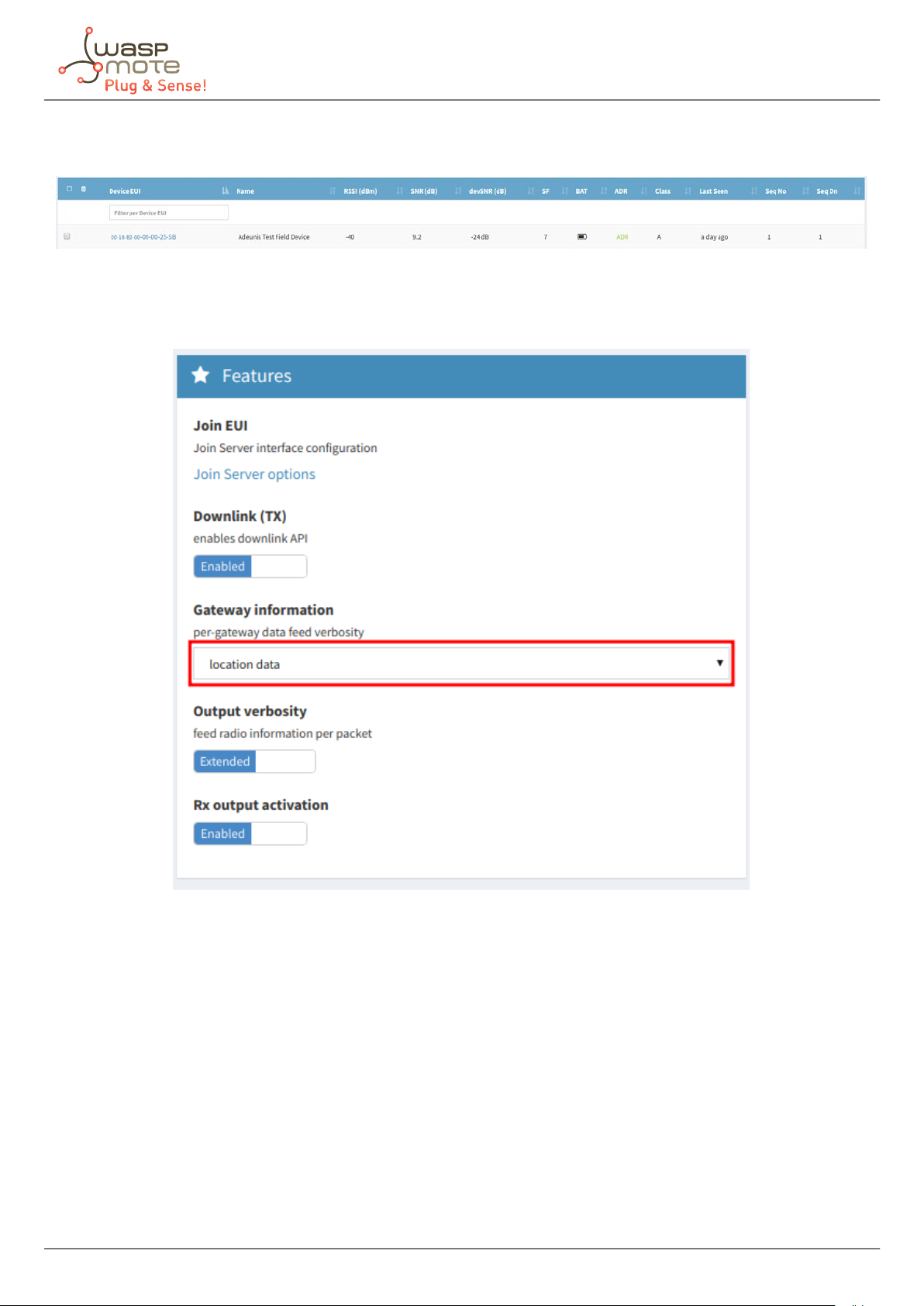
If the form has been lled properly, after clicking “Enroll”, there should be a new device among the other devices
registered in the Loriot application.
Figure: New device
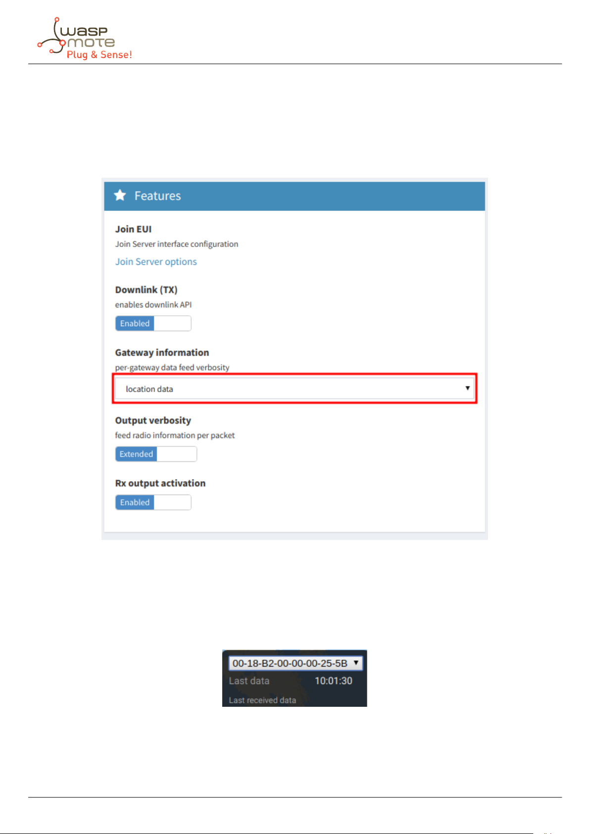
Additionally, in the Loriot Application where the device has been dened, the “Gateway information” selection
must be set to “Location data”.
Figure: Loriot application menu
-12- v7.0
Page 13
Working mode
3.2. Testing the device
Once the device has been registered properly in Loriot, it can be turned on and start working. Refer to the “User
interface” section to see how to power up the device and what to expect when the device is connected.
To see the packets sent to the back-end from the device, Loriot has developed the “Adeunis GPS” websocket
application. It parses the data and locates packets on a map.
Figure: Websocket applications menu
The application may take several minutes before showing packets and position. In order to show them, it is also
necessary for the module to be sending packets with location. Before start sending packets, it is recommended
to give a minute to the device so it gets GPS coverage. Once the device shows its position, pockets should start
being shown in the application.
Remember to select the Adeunis FTD registered unit in the application within the Adeunis GPS app.
Figure: Selected device menu
-13- v7.0
Page 14

Working mode
On the left side of the map, there is a box that shows the information of the last packet received. On the right
side, there is another box that shows a list with some information of the packets stored in the database. Dots are
displayed in the map indicating the place where the packets were sent from.
Figure: Adeunis GPS application
-14- v7.0
Page 15

Working mode
3.3. Universal Ranger application
Besides the Adeunis GPS application, Loriot provides a Universal Ranger that also shows the strength of the signal
and location of packets in a map in a very similar way to the Adeunis GPS application. It is also fully compatible
with the Adeunis FTD. Please check the Network Ranger Application Guide if you are interested.
Figure: Universal Ranger application
-15- v7.0
Page 16

Working mode
3.4. General recommendations
Before starting the test, we advise to power up the device close to the base station, and having a computer with
access to the Loriot back end, in case there is some conguration that hasn’t been done yet. Once the device
shows data in the application, the test shall begin correctly.
The device is prepared to work using th ADR (Adaptive Data Rate), so Libelium has congured it to start working with
SF7 (spreading factor 7). This is the fastest wireless transmission mode, but bear in mind that it is the worst mode
for getting long distances. If the packets do not reach the gateway during the test, the device will automatically
change SF from SF7 to SF12. The higher is the spreading factor, the longer is the range.
If the packets do no reach the gateway, the user will see that the device does not receive ACK frames. This will
mean that the user has exceeded the limit of the coverage area.
If the customer is interested in sending a high number of packets per day, attending always to the country
regulations, it is recommended to nd places where the device can send with lower spreading factors. The lower
the spreading factor is, the faster the transmission of the packet is (as packets take less time on air, more packets
can be send).
It is also recommended to restart the Adeunis FTD at every location in order to check that the device joins properly
to the network.
-16- v7.0
 Loading...