

Page 1

Page 2
Thismanualisonlyforoperatinginstructionsanddoesnotserveasrepairingservice.
Changes
Liantronicsprovidesthismanual ‘asis’ withoutwarrantyofanykind,eitherexpressedorimplied,
includingbutnotlimitedtotheimpliedwarrantiesormerchantabilityandfitnessforaparticular
purpose.Liantronicsmaymakeimprovementsand/orchangestotheproduct(s)and/orthe
program(s)describedinthispublicationatanytimewithoutnotice.
Thispublicationcouldcontaintechnicalinaccuraciesortypographicalerrors.Changesare
periodicallymadetotheinformationinthispublication;thesechangesareincorporatedinnew
editionsofthispublication.
Copyright
Allrightsreserved.ThecopyrightofthismanualisprotectedbytheCopyrightLawofthePeople's
RepublicofChinaandotherintellectualpropertylaws.Nopartofthisdocumentmaybecopied,
reproduced,distributed,translated,orusedforcommercialpurposes.Itshallnototherwisebe
recorded,transmittedorstoredinaretrievalsystemwithoutthepriorwrittenconsentofLiantronics.
LIANTRONICSCO.,LTD
Add:LiantronicsBuilding,No.1Liuxian3rdRoad,Section68,
BaoanDistrict,Shenzhen,China
Postcode:518101
E-mail:oversea@liantronics.com;service@lcjh.com
Visitusattheweb: www.liantronics.com
Page 3
Contents
1.Safety…………………………………………….…………………….……………..1
2.InstallationRequirements…………………………………………………………3
2.1 MechanicalRequirements………………………………………………………………………….3
2.2 ElectricalRequirements…………………………………………………………………………….4
2.3 SystemRequirements............................................................................................................5
3.SystemIntroduction.………………………………………………………….……6
3.1 BriefIntroduction……………………….…………..…………………………………....……..…...6
3.2 SystemComponents………………….………..……………………………………………..........6
3.3 LEDDisplayComponents………..……….…………………………………………………….….9
3.4 LEDControlSystem.………..…….…………………………………....…….………………......13
3.5 LEDSystemControlSoftware…...…….……………………………………………………......16
3.6 PeripheralDevice…………………..………………………………………………………….......17
3.7 PowerDistributionSystem……… ...…………………………………....…….…………............19
4.SetupProcess………………………………………………………….…………..21
4.1 InstallationPreparation……..…………………………………....…………………………….....21
4.2 SetupProcessofrearStandingInstallation…………………………………....……………...23
4.3 SetupProcessofFrontStandingInstallation ……………………….……….....……………...27
4.4 DataCabling……..………………………..………....………………………………………..…..31
4.5 PowerCabling…………………….………………………………....………………………….....32
4.6 SystemConnection..………...………………………....………………………………………....33
5.Start-upoftheSystem……………………………………………………….…...34
5.1 Softwareinstallation………...……………………………………………………………………...34
5.2 SystemOperation…………………………………………………………………………………..34
6.TroubleShooting………………………………………………………………….38
6.1 SoftwareTrouble……………..…………………………………………………………………….38
6.2 HardwareTrouble………..…...……………………………………………………………………39
6.3 ModuleProblems……..……...…………………………………………………………………….40
6.4 PowerProblems……….…………………………………………………………………………...40
6.5 DataTransferProblems……..………..…………………………………………………………..40
7.Maintenance.………………………………………………………………………..41
AppendixA.TechnicalSpecification.…………………………………………….43
AppendixB.TileDimensions.……………………………………………………...44
AppendixC.Package.……………………………………………………………….45
FC series User Manual
Page 4

Page 5
www.liantronics.com
1.SAFETY
Thischaptercontainsimportantinformationtopreventpersonalinjuryandproductdamagewhen
youinstallthedisplay.Readthischapterandkeepitproperly.Ensurethatyouunderstandandfollow
allthesafetyinstructionsandwarningsinthischapterbeforeinstalling.
PersonalProtection
Personnelofinstallationandmaintenance
Theinstallationandmaintenanceofthisproductmustbeperformedbyauthorizedandqualified
technicalpersonnelonly.Themanufacturedosenottakeresponsibilityfortheresultscausedby
incorrect,improper,irresponsibleandunsafeactions.
GNDandLightningprotection
Donotunderestimatethesafetyprotectionofgroundingplug/socket.Ifthesuppliedplug/socketis
defective,replacethedefectiveparts.Groundtheproductcorrectlytoavoidelectricshockcausedby
largeelectricityleakage.
Disconnectthepowerinthetimeoflightning,orprovideothersuitablelightningprotectiondevice.
Disconnectthepowerplugwhentheproductisnotusedinalongperiod.
Ambienceofinstallationanduse
• TheambienttemperatureforLEDdisplay:max60°C,min-40°C.
• Ensurethattheventilationisgood.Donotjamordropmetalparticlesandcablepiecesinto
ventilationopening.Keeptheventilationsurfaceclearwithoutforeignmatterslikewrapping
materials.Falseactionsmayleadtopoorventilationandcausefire,malfunctionanderror.
• InstallLEDdisplayfarawayfromradiator,heater,furnaceandotherequipmentshindering
ventilationandheatdissipation(includingbutnotlimitedtoamplifier,laser,ultrasonicvibration
devices),flammablematerials(likecurtains)andotherunsafedevices.
• I/Osignalcablesshouldbeshieldedtorestrainthehigh-frequencyinterference.
• LEDdisplaycannotcontactwithanycorrosiveandabrasivematter.DonotuseLEDdisplayin
moistambience,inambiencecontainingairbornecontaminant,dust,oilyfume,corrosivegasand
flammablegas,andinambiencewithvibrationandshock.
• ThisLEDindoorproductisdesignedonlyforindooruse.Neverinstallanduseitinoutdoor
environmentandkeepitfarawayfromdirectsunlight,dustandmoisture.
Warning: Ensure thatyou understand and follow all the safety instructions,
warnings mentioned in this manual.
Warning: Pay attention to electric shock.
Warning: Weara hard hat to reduce the risk of personal injury.
Warning: Be awareof suspended loads.
Warning: Mind your fingers while dealing with heavyloads.
1
FC series User Manual
Page 6
ESDandLED:
LEDcomponentsareESD(Electro-staticDischarge)sensitive.DonottouchLEDcomponentswhen
thedisplayisinoperationorswitchedoff.
Disconnectdevice:
Whentheapplianceinletsoftheindividualtilesarenotaccessible,thesocketoutletssupplyingthe
rackshallbeinstalledneartheequipmentandbeeasilyaccessible,orareadilyaccessiblegeneral
disconnectdeviceshallbeincorporatedinthefixedwiring.
Mountingparts:
ThemountingpartsareonlyusedtoinstallLEDdisplay.Donotrepairorcopy.Onlyuseparts
appointedbythemanufacturer.ContactLIANTRONICSifyouwantcustomizedapplication.
Productcare:
Inspectallinstallationsonaroutinebasistochecksecurity,wear,deformation,corrosionorany
othersituationthatreducesload-carryingcapability.Increaseinspectionfrequencyforkeyparts.
Keepstructuralandmountingpartsdry,clean,lubricated(onlyifrecommended),coatedproperly,
andmaintaincomplyingwithpartdesign.Defectivepartsmustberemovedorreplacedatonce.
Installationandwiring:
Installthedisplayandconnectcablesfollowingthemanualinstructions.Theinstallationandwiring
mustbesecure.Poorconnectionmayleadtomalfunction.Donotsteponpower/datacableor
squeezeplug,socketandpower/datacable.Donotsuspendanyitemsoncablesorthebackof
LEDdisplay.Connectordisconnectthecablesofdatacommunication,extensionmoduleorcontrol
unitafterthepowerisofftopreventproductdamageormalfunction.
Riskofelectricshock:
• Toavoidelectricshockanddamage,donotdismantletheinsideelectricalparts.
• Donothotpluggingthecablestopreventelectricshockorcircuitdamage.
• Keepcleanafterinstallingandcabling.Beensureallthedevicesandterminalsarecovered
beforetuneonthepower.
• Donottouchtheterminalswhenpowerison.Cleanandscrewtheterminalswhenpowerisoff.
Movingortransportingproduct:
DonothitthecornersofLEDtileswheninstallingordismantlingLEDtiles.Becarefulwhenmoving
ortransportingtheproducttopreventanydamage.
LEDtilescannotbetransportedincontainersotherthanLIANTRONICSflightcasesorpackaging.
EventheuseofLIANTRONICSpackagingdoesnotguaranteetheLEDtilesagainstdamagedue
toexcessiveforceofimpacts.Allwarrantyclaimsregardingdamagedmodulesduetoincorrect
packingwillberenderedinvalid.
2
FC series User Manual
Page 7
2.INSTALLATIONREQUIREMENTS
Thischapterspecifiestherequirementsforsafety,mechanism,electricityandcontrolsoftwareofFC
SeriesLEDdisplay.
Warning: ThisLEDindoorproductisdesignedonlyforindooruse.Neverinstallanduseit
inoutdoorenvironmentandkeepitfarawayfromdirectsunlight,dustandmoisture.
2.1MechanicalRequirements
Weight
Warning:DonotunderestimatetheweightofacompleteFCSeriesLEDdisplay.Besure
thattheflooronwhichtheFCdisplayhastobeinstallediscapableofhandlingfive(5)
timesthecompleteloadofthedisplay.Forfloormounting,concludetheweightofany
otherload.
Caution: OneFCtileweighsapproximately11kg.
Horizontalsurface
Forfloorinstallation,theflooronwhichFCdisplayisinstalledmustbehorizontal.NeverinstallLED
displayonaslantsurface.
Ballast
DependingontheheightofthedisplayandthepositionoftheLEDdisplayuponthefootbeams
(somewherebetweenfrontandmiddle), additionalweight(ballast)willberequired.Consult
professionalsofLIANTRONICStocalculatetheminimumballastyourequireforsafeinstallationof
theLEDdisplay.
Installationambience
• Environmentalconditions:humidity,ventilation,temperature,etc.
• Location:Altitude,etc.
• Frontclearances: foroptimaleffect,ensurethatenoughfreespaceissuppliedinfrontofthe
LEDdisplayandrespecttheminimumviewingdistance.
• Complywithlocalregulationsregardingsuchinstallations.
3
FC series User Manual
Page 8
2.2ElectricalRequirements
Powerrequirements
ThedisplayingareaofoneFCtileis0.332m².FCSeriesLEDtileshavedifferentpixeldensities
(seeAppendixA–technicalspecifications).Fordifferentpixeldensities,oneFCtilemayneed
powersupplyof0.6ampsto1.5ampsat220VAC,100-250VAC,50-60Hz.EachFCtilehasone
inputandoneoutputsocketofACpower.Thepowerisdistributedtodisplaytilesbypowersplit
cablesfrompowerdistributor.However,onepowersplitcablecanbeconnectedwith8–20tilesin
parallel.So,onepowersplitcablehastobeprovidedforevery8–20tiles.
Protecteverypowercablebyacircuitbreakerorfusesrated16A/250VAC(15A/110VACinthe
USAandCanada).LIANTRONICSprovidesarangeofpowerdistributortosatisfythedemandsof
yourLEDdisplay.SeemoredetailsforpowerdistributorofLEDdisplayinPowerDistribution
Section.ContactLIANTRONICSformoreinformation.
Powersystem
Itisrecommendedtousepowerdistributionsystemwithaseparateneutralandgrounding
conductortoavoidlargecurrentloopsduetovoltagedifferencesintheneutralconductor.
• Protecttheelectricalinstallationbyswitch,circuitbreaker,over-voltageprotector,defective-
groundingcircuitbreakerwithproperratedpower.
• Installthedisplayinaccordancewithlocalelectricalinstallationstandards.InEurope,comply
withEN60364,thestandardforelectricalinstallationofbuildings.InGermany,complywithEN
60364.InAmerica,complywithNationalElectricalCodeANSI/NFPA70.
Protectivegrounding
Topreventagainsttheriskofelectricshock,theinstallationshouldbeproperlygrounded.Defeating
thepurposeofgroundingwillexposeyoutotheriskofelectricshock.
4
FC series User Manual
Page 9
2.3SystemRequirements
Beforeyoubegin,itisassumedthatyouarefamiliarwiththeWindowsoperatingsoftware.TheCD-
ROMinyourpackagecontainsaWindows7-basedinstallationprogram.Youcaninstallthe
softwarefromtheCD-ROM.
Systemrequirements
Minimumspecifications:
l Hardware
n PCPentiumIV2.0GHzorequivalent
n 1GBRAM
n Freeharddiskspace:10GB
n XGAresolution(1024x768)
n Serialcommunicationport
n Ethernetconnection
l Software
n Windows7Professional
Recommendedspecifications:
l Hardware
n PCInteli5processororabove
n 4GBRAM
n Freeharddiskspace:500GB
n SXGAresolution(1280x1024),with512MBvideomemory
n Serialcommunicationport
n Ethernetconnection
l Software
n Windows7Professional
5
FC series User Manual
Page 10
3.SYSTEMINTRODUCTION
3.1BriefIntroduction
FCseriesistheLEDindoordisplayproductofLIANTRONICSthatusesdie-castingaluminumframe
withCNChighprecisionmachiningtechniques.Withitscompact,lightandhandyexterior,theLED
tileiseasytoinstallanddisassemble.Asthetiledimensionisofveryhighprecision,sothewhole
displaykeepsinhighflatnessandseamless.
3.1.1KeyBenefits
• Supportforbothfrontandrearmaintenance.
• Uniformcolorandhighcontrast,ensuringclearandsharppicture
• Highprecisiondie-castingaluminumtile,achievinghighflatnessandseamlessmatchingofthe
wholedisplay
• Fan-lessdesignwithgoodheatdissipation,achievingnoise-free
• Lightandslimtile,easiertohandleandtransport
• Highstabilityandreliability,prolonginglifespanofthedisplay
3.1.2Applications
Indoorhall,multi-functionalconferencehall,performinghall,theater,stage,commandandcontrol
centerandsoon.
3.2SystemComponents
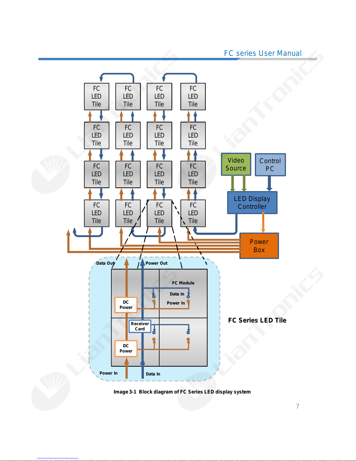
FCseriesLEDdisplaysystemincludesthefollowingbasiccomponents:
• LEDDisplay: FCseriesLEDdisplaytiles,powersupplycables,signalcables,connectors
• ControlSystem:controlcomputer,LEDdisplaycontroller,distributor,controlsystemsoftware
• PowerDistributionSystem:powerdistributionbox,powercables
• PeripheralDevices: videoprocessor,opticalfibertransmitter
6
FC series User Manual
Page 11
Control
PC
Power
Box
LED Display
Controller
FC
LED
Tile
FC
LED
Tile
FC
LED
Tile
FC
LED
Tile
FC
LED
Tile
FC
LED
Tile
FC
LED
Tile
FC
LED
Tile
FC
LED
Tile
FC
LED
Tile
FC
LED
Tile
FC
LED
Tile
Video
Source
FC
LED
Tile
FC
LED
Tile
FC
LED
Tile
FC
LED
Tile
FC Module
Power OutData Out
Power In
Data In
Receiver
Card
DC
Power
DC
Power
Power In
Data In
FC Series LED Tile
Image 3-1 Block diagram of FC Series LED display system
7
FC series User Manual
Page 12
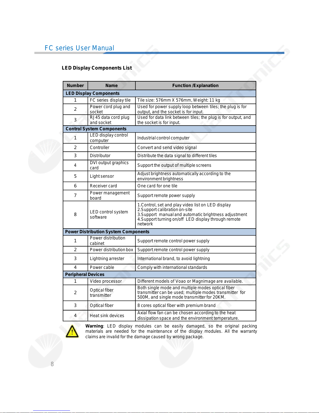
LEDDisplayComponentsList
Warning:LEDdisplaymodulescanbeeasilydamaged,sotheoriginalpacking
materialsareneededforthemaintenanceofthedisplaymodules.Allthewarranty
claimsareinvalidforthedamagecausedbywrongpackage.
Number Name Function/Explanation
LED Display Components
1 FC series display tile Tilesize:576mmX576mm,Weight:11kg
2
Power cord plug and
socket
Used for power supply loop between tiles; the plug is for
output, and the socket is for input.
3
RJ45 data cord plug
and socket
Used for data link between tiles;the plug is for output, and
the socket is for input.
Control System Components
1
LED display control
computer
Industrial control computer
2 Controller Convert and send video signal
3 Distributor Distribute the data signal to different tiles
4
DVI output graphics
card
Support the output of multiple screens
5 Light sensor
Adjust brightness automatically according to the
environment brightness
6 Receiver card One card for one tile
7
Power management
board
Support remote power supply
8
LED control system
software
1.Control, set and play video list on LED display
2.Support calibration on-site
3.Support manual and automatic brightness adjustment
4.Support turning on/off LED display through remote
network
Power Distribution System Components
1
Power distribution
cabinet
Support remote control power supply
2 Power distribution box Support remote control power supply
3 Lightning arrester International brand, to avoid lightning
4 Power cable Comply with international standards
Peripheral Devices
1 Video processor Different models of Voao or Magnimage are available.
2
Optical fiber
transmitter
Both single mode and multiple modes optical fiber
transmitter can be used; multiple modes transmitter for
500M, and single mode transmitter for 20KM.
3 Optical fiber 8 cores optical fiber with premium brand
4 Heat sink devices
Axial flow fan can be chosen according to the heat
dissipation space and the environment temperature.
8
FC series User Manual
Page 13
3.3LEDDisplayComponents
FCTile
FCseriesLEDdisplayisbuiltwithFCtiles.Atileconsistsofdie-castingaluminumframesinhigh
accuracy,FCdisplaymodules,switchingpowersupply,receivercards,andsomeothermechanical
andelectricalconnectionparts.TheFCdie-castingaluminumframeadoptsonetimedie-casting
andCNCprecisionprocessingtechnologywithhighqualityaluminumtoensurethehighaccuracy
oftheframeandtheuniformityofthewholedisplay.
TheintroductionofthemaincomponentsofFCtileisshownasbelowwithrelatedimages.
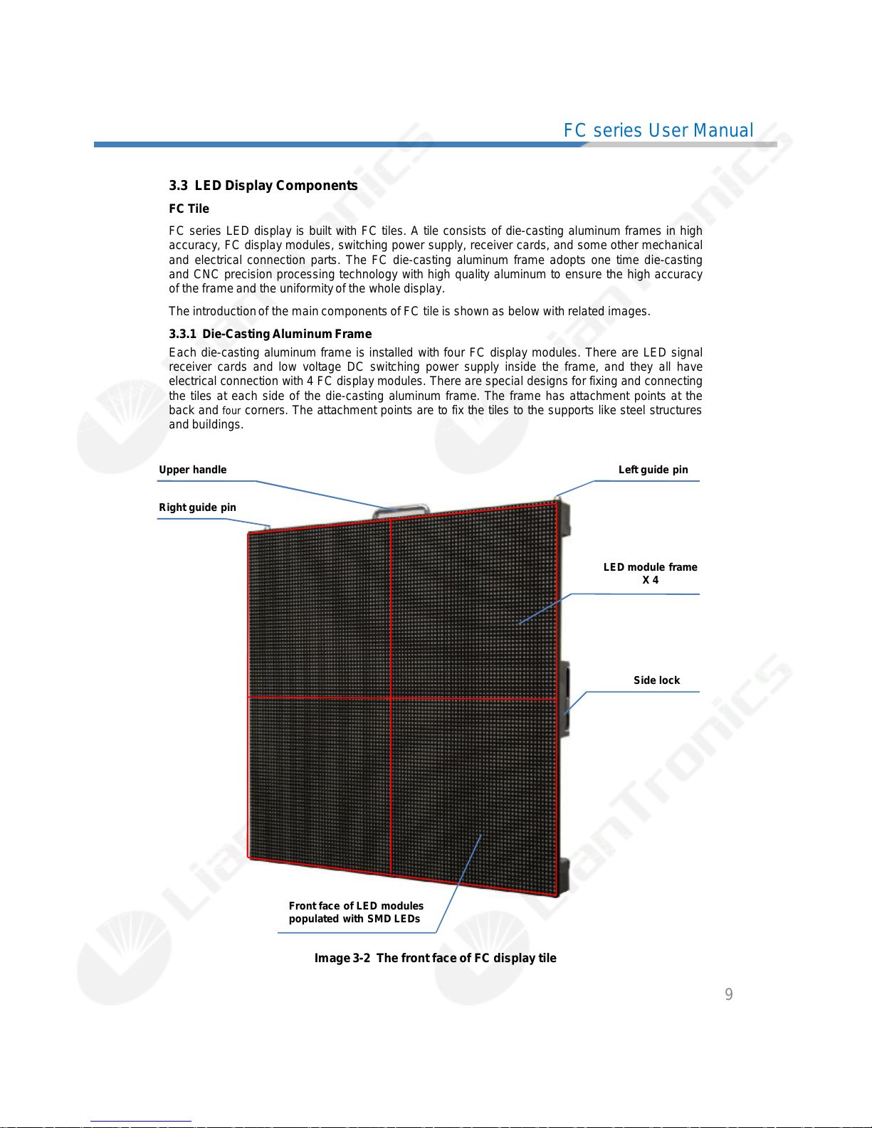
3.3.1 Die-Casting Aluminum Frame
Eachdie-castingaluminumframeisinstalledwithfourFCdisplaymodules.ThereareLEDsignal
receivercardsandlowvoltageDCswitchingpowersupplyinsidetheframe,andtheyallhave
electricalconnectionwith4FCdisplaymodules.Therearespecialdesignsforfixingandconnecting
thetilesateachsideofthedie-castingaluminumframe.Theframehasattachmentpointsatthe
backand four corners.Theattachmentpointsaretofixthetilestothesupportslikesteelstructures
andbuildings.
Image 3-2 The front faceof FC display tile
LeftguidepinUpperhandle
Rightguidepin
LEDmoduleframe
X4
Sidelock
FrontfaceofLEDmodules
populatedwithSMDLEDs
9
FC series User Manual
Page 14
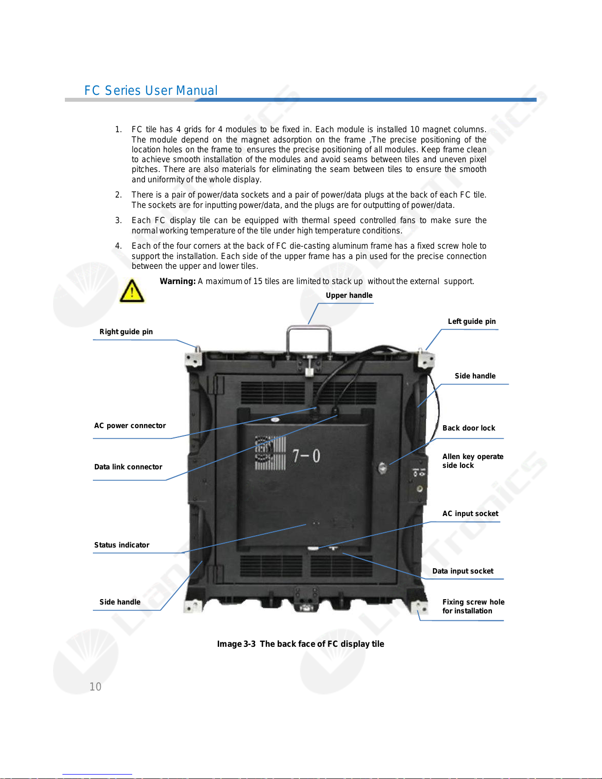
1. FCtilehas4gridsfor4modulestobefixedin.Eachmoduleisinstalled10magnetcolumns.
Themoduledependonthemagnetadsorptionontheframe,Theprecisepositioningofthe
locationholesontheframetoensurestheprecisepositioningofallmodules.Keepframeclean
toachievesmoothinstallationofthemodulesandavoidseamsbetweentilesandunevenpixel
pitches.Therearealsomaterialsforeliminatingtheseambetweentilestoensurethesmooth
anduniformityofthewholedisplay.
2. Thereisapairofpower/datasocketsandapairofpower/dataplugsatthebackofeachFCtile.
Thesocketsareforinputtingpower/data,andtheplugsareforoutputtingofpower/data.
3. EachFCdisplaytilecanbeequippedwiththermalspeedcontrolledfanstomakesurethe
normalworkingtemperatureofthetileunderhightemperatureconditions.
4. EachofthefourcornersatthebackofFCdie-castingaluminumframehasafixedscrewholeto
supporttheinstallation.Eachsideoftheupperframehasapinusedforthepreciseconnection
betweentheupperandlowertiles.
Warning: Amaximumof15tilesarelimitedtostackupwithouttheexternalsupport.
Image 3-3 The back faceof FC display tile
10
FC Series User Manual
Upperhandle
Leftguidepin
Sidehandle
Backdoorlock
Statusindicator
Allenkeyoperate
sidelock
ACinputsocket
Fixingscrewhole
forinstallation
ACpowerconnector
Datalinkconnector
Sidehandle
Rightguidepin
Datainputsocket
Page 15
11
3.3.2 FC Module
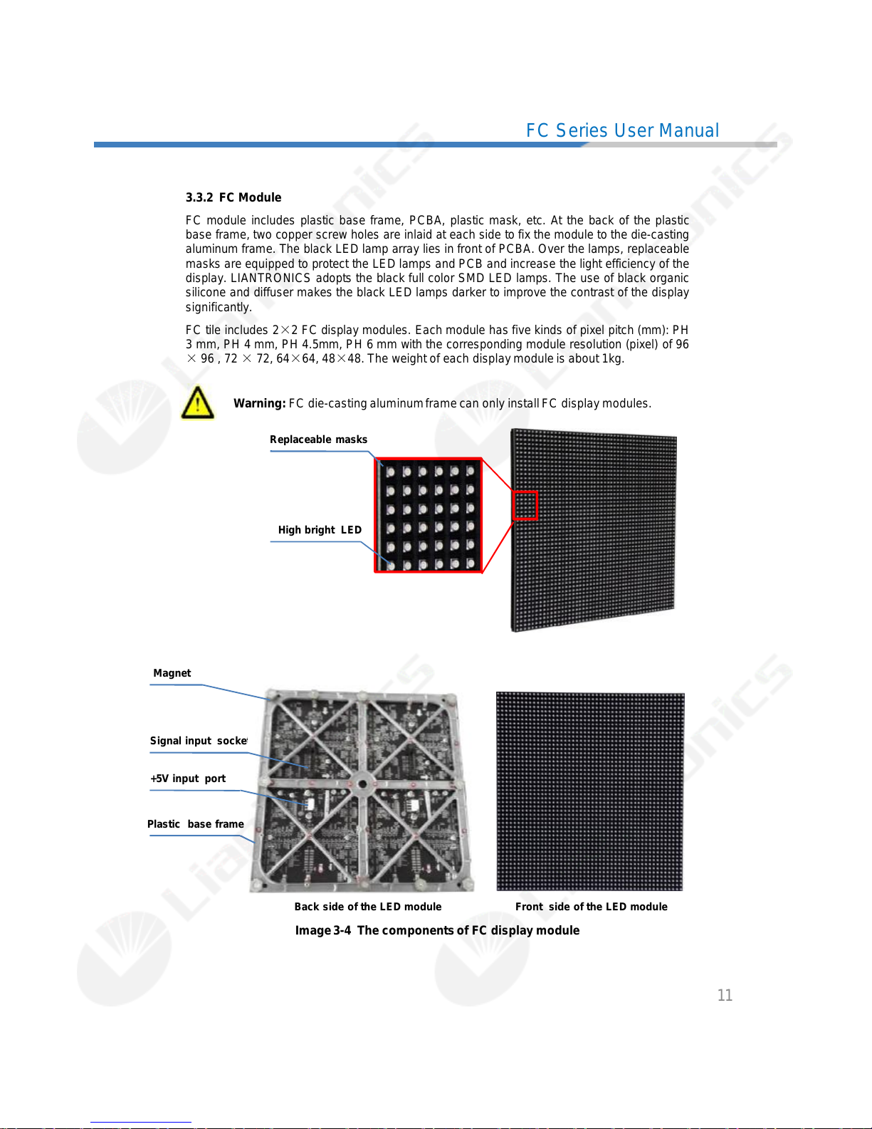
FCmoduleincludesplasticbaseframe,PCBA,plasticmask,etc.Atthebackoftheplastic
baseframe,twocopperscrewholesareinlaidateachsidetofixthemoduletothedie-casting
aluminumframe.TheblackLEDlamparrayliesinfrontofPCBA.Overthelamps,replaceable
masksareequippedtoprotecttheLEDlampsandPCBandincreasethelightefficiencyofthe
display.LIANTRONICSadoptstheblackfullcolorSMDLEDlamps.Theuseofblackorganic
siliconeanddiffusermakestheblackLEDlampsdarkertoimprovethecontrastofthedisplay
significantly.
FCtileincludes2×2FCdisplaymodules.Eachmodulehasfivekindsofpixelpitch(mm):PH
3mm,PH4mm,PH4.5mm,PH6mmwiththecorrespondingmoduleresolution(pixel)of96
× 96,72 × 72,64×64,48×48.Theweightofeachdisplaymoduleisabout1kg.
Warning: FCdie-castingaluminumframecanonlyinstallFCdisplaymodules.
Image 3-4 The components of FC display module
FC Series User Manual
Replaceable masks
High bright LED
Back side of the LED module Front side of the LED module
Plastic base frame
+5V input port
Signal input socket
Magnet
Page 16
3.3.3SocketandPlugforPowerandDataConnection
Thefollowingtwotypesofsocketandplugarerespectivelyusedforthepoweranddata
connectionbetweenFCdisplaytiles.Thepowersocketandplugisforthelooppower
connectionbetweenupperandlowertiles,andthedatasocketandplugisfortheloopdata
connectionbetweentiles.
Image 3-5 Power and data plug and socket Image 3-6 Power and data plug and socket
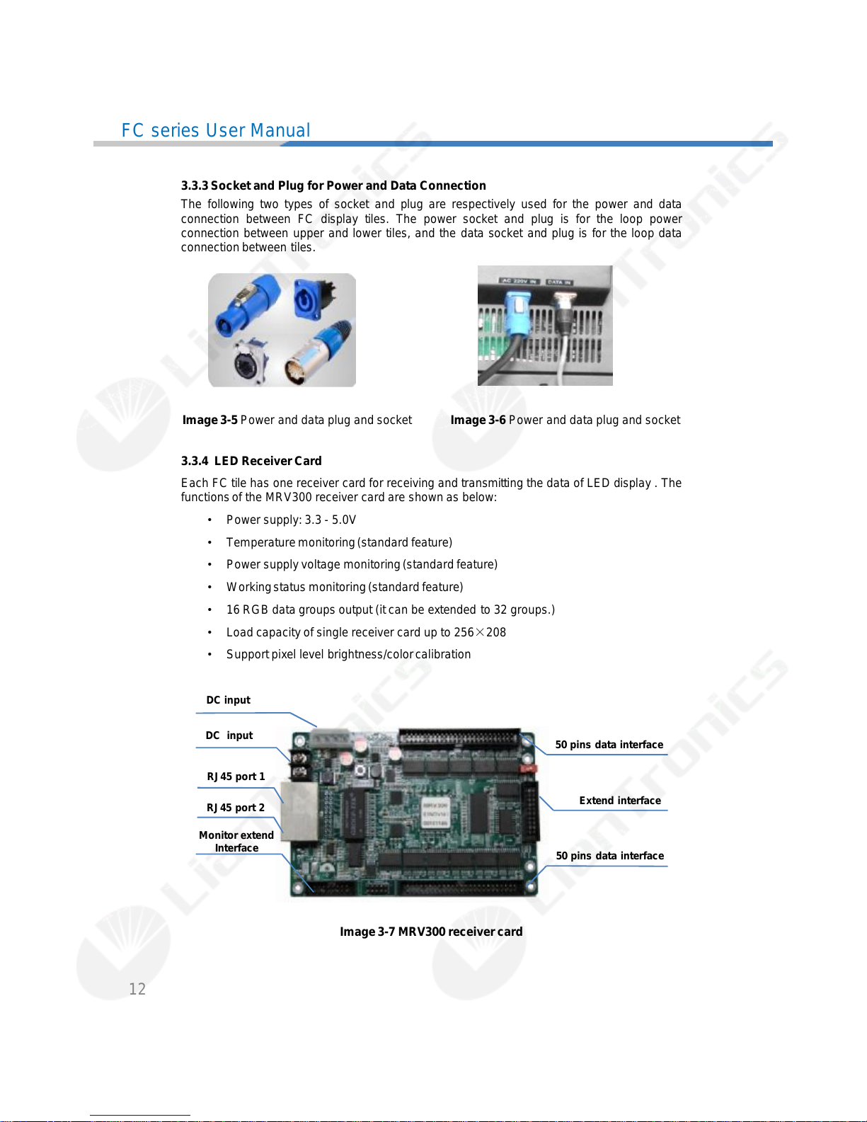
3.3.4LEDReceiverCard
EachFCtilehasonereceivercardforreceivingandtransmittingthedataofLEDdisplay.The
functionsoftheMRV300receivercardareshownasbelow:
• Powersupply:3.3-5.0V
• Temperaturemonitoring(standardfeature)
• Powersupplyvoltagemonitoring(standardfeature)
• Workingstatusmonitoring(standardfeature)
• 16RGBdatagroupsoutput(itcanbeextendedto32groups.)
• Loadcapacityofsinglereceivercardupto256×208
• Supportpixellevelbrightness/colorcalibration
Image 3-7MRV300 receiver card
12
FC series User Manual
50 pins data interface
Extend interface
DC input
DC input
RJ45 port 1
RJ45 port 2
Monitor extend
Interface
50 pins data interface
Page 17
3.4LEDControlSystem
ThischapterintroducesthecontrolsystemandsoftwareofA24display.
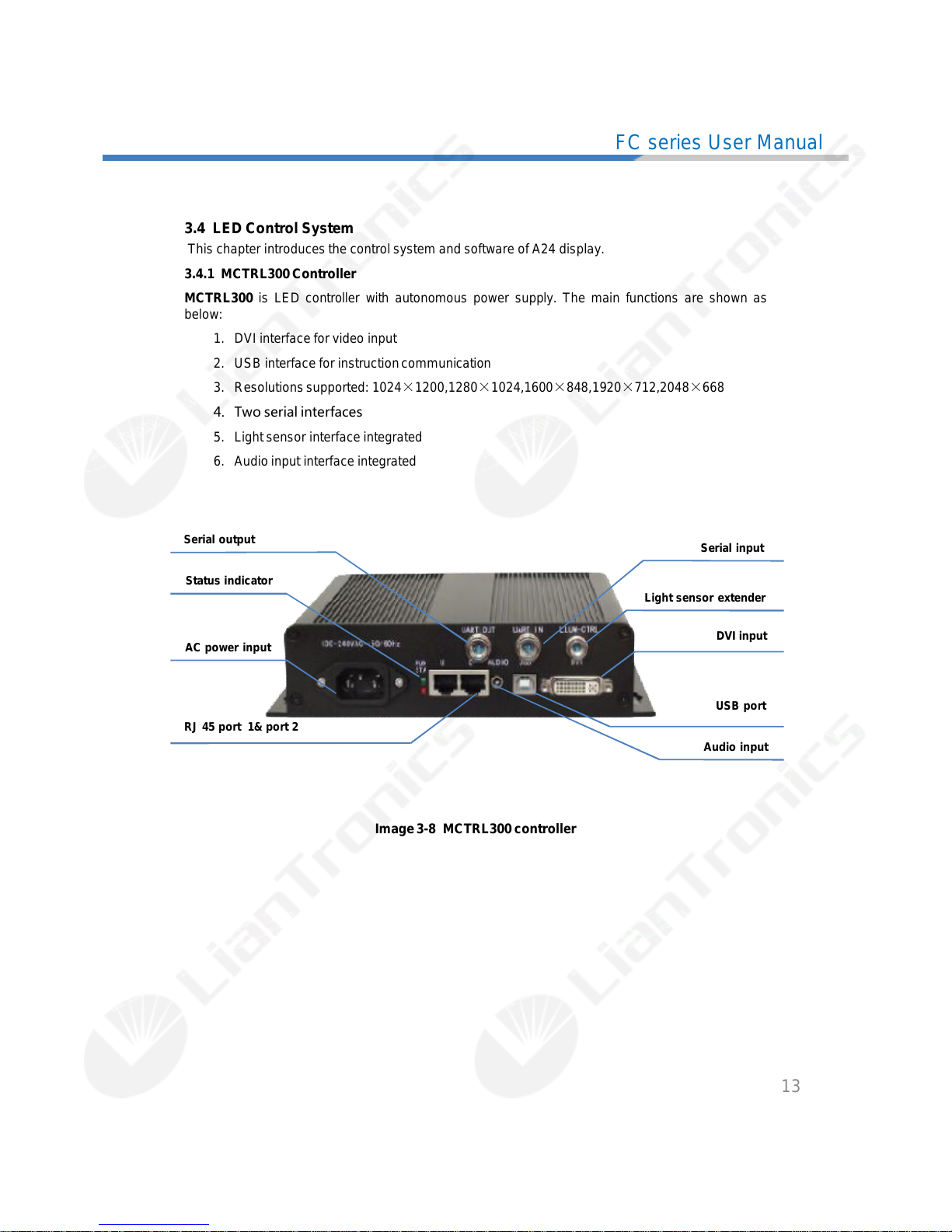
3.4.1MCTRL300Controller
MCTRL300 isLEDcontrollerwithautonomouspowersupply.Themainfunctionsareshownas
below:
1.DVIinterfaceforvideoinput
2.USBinterfaceforinstructioncommunication
3.Resolutionssupported:1024×1200,1280×1024,1600×848,1920×712,2048×668
4.Twoserialinterfaces
5.Lightsensorinterfaceintegrated
6.Audioinputinterfaceintegrated
Image 3-8 MCTRL300 controller
13
FC series User Manual
Serial output
Serial input
Light sensor extender
AC power input
Status indicator
RJ 45 port 1& port 2
DVI input
USB port
Audio input
Page 18
14
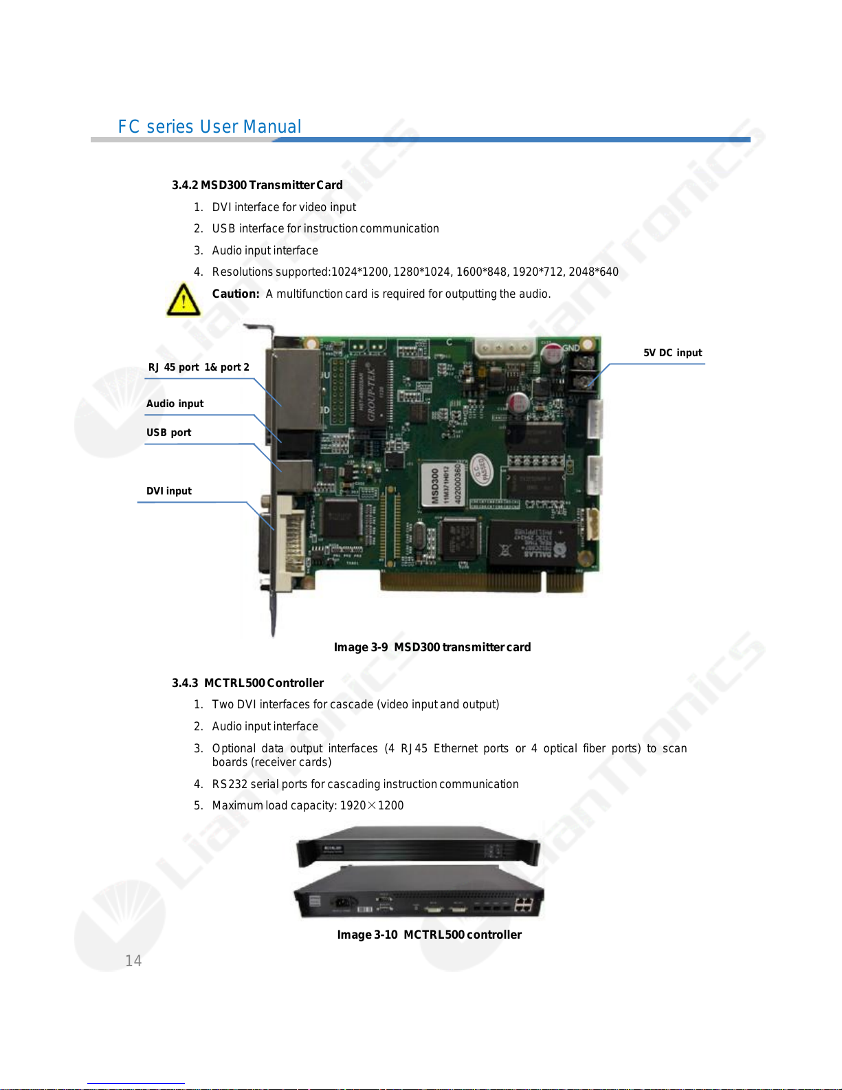
3.4.2MSD300TransmitterCard
1.DVIinterfaceforvideoinput
2.USBinterfaceforinstructioncommunication
3.Audioinputinterface
4.Resolutionssupported:1024*1200,1280*1024,1600*848,1920*712,2048*640
Caution: A multifunction card is required for outputting the audio.
Image 3-9 MSD300transmitter card
3.4.3MCTRL500Controller
1.TwoDVIinterfacesforcascade(videoinputandoutput)
2.Audioinputinterface
3.Optionaldataoutputinterfaces(4RJ45Ethernetportsor4opticalfiberports)toscan
boards(receivercards)
4.RS232serialportsforcascadinginstructioncommunication
5.Maximumloadcapacity:1920×1200
Image 3-10 MCTRL500controller
FC series User Manual
USB port
Audio input
DVI input
5V DC input
RJ 45 port 1& port 2
Page 19
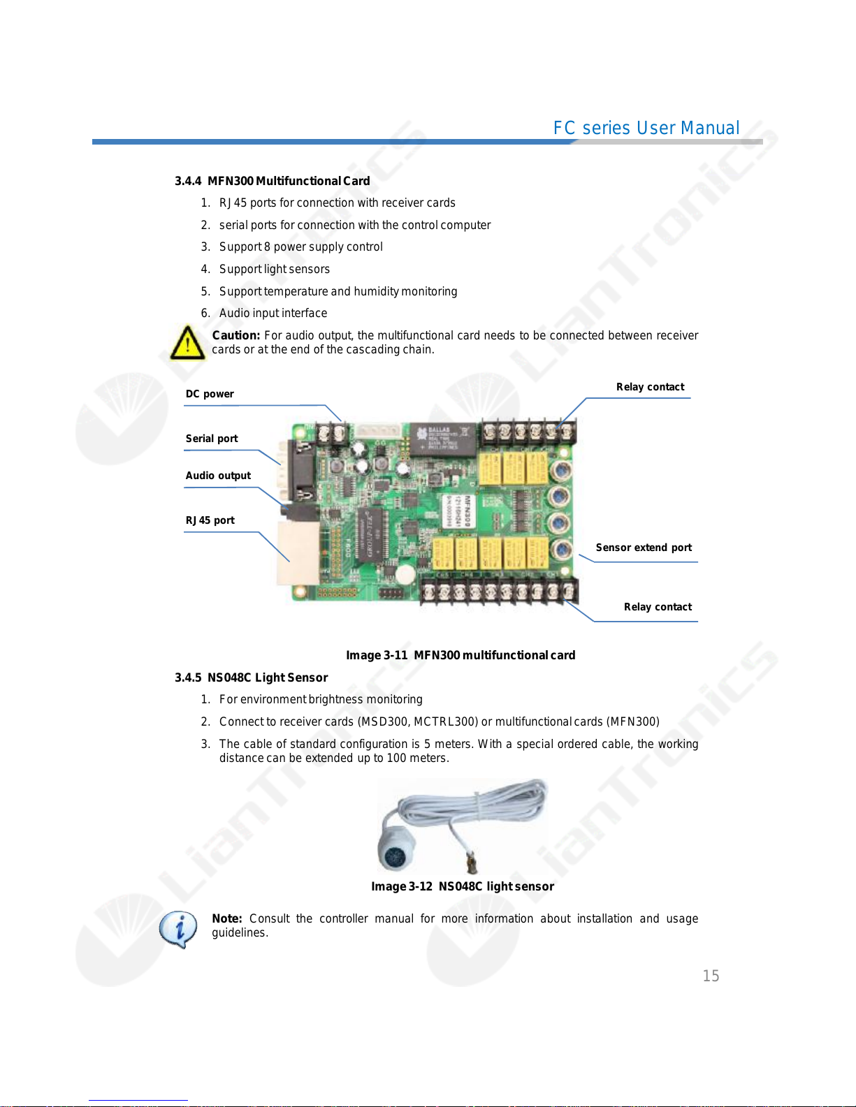
3.4.4MFN300MultifunctionalCard
1.RJ45portsforconnectionwithreceivercards
2.serialportsforconnectionwiththecontrolcomputer
3.Support8powersupplycontrol
4.Supportlightsensors
5.Supporttemperatureandhumiditymonitoring
6.Audioinputinterface
Caution: Foraudiooutput,themultifunctionalcardneedstobeconnectedbetweenreceiver
cardsorattheendofthecascadingchain.
Image 3-11 MFN300multifunctional card
3.4.5NS048CLightSensor
1.Forenvironmentbrightnessmonitoring
2.Connecttoreceivercards(MSD300,MCTRL300)ormultifunctionalcards(MFN300)
3.Thecableofstandardconfigurationis5meters.Withaspecialorderedcable,theworking
distancecanbeextendedupto100meters.
Image 3-12 NS048C light sensor
Note: Consultthecontrollermanualformoreinformationaboutinstallationandusage
guidelines.
15
FC series User Manual
Serial port
Audio output
RJ45 port
DC power
Relay contact
Relay contact
Sensor extend port
Page 20
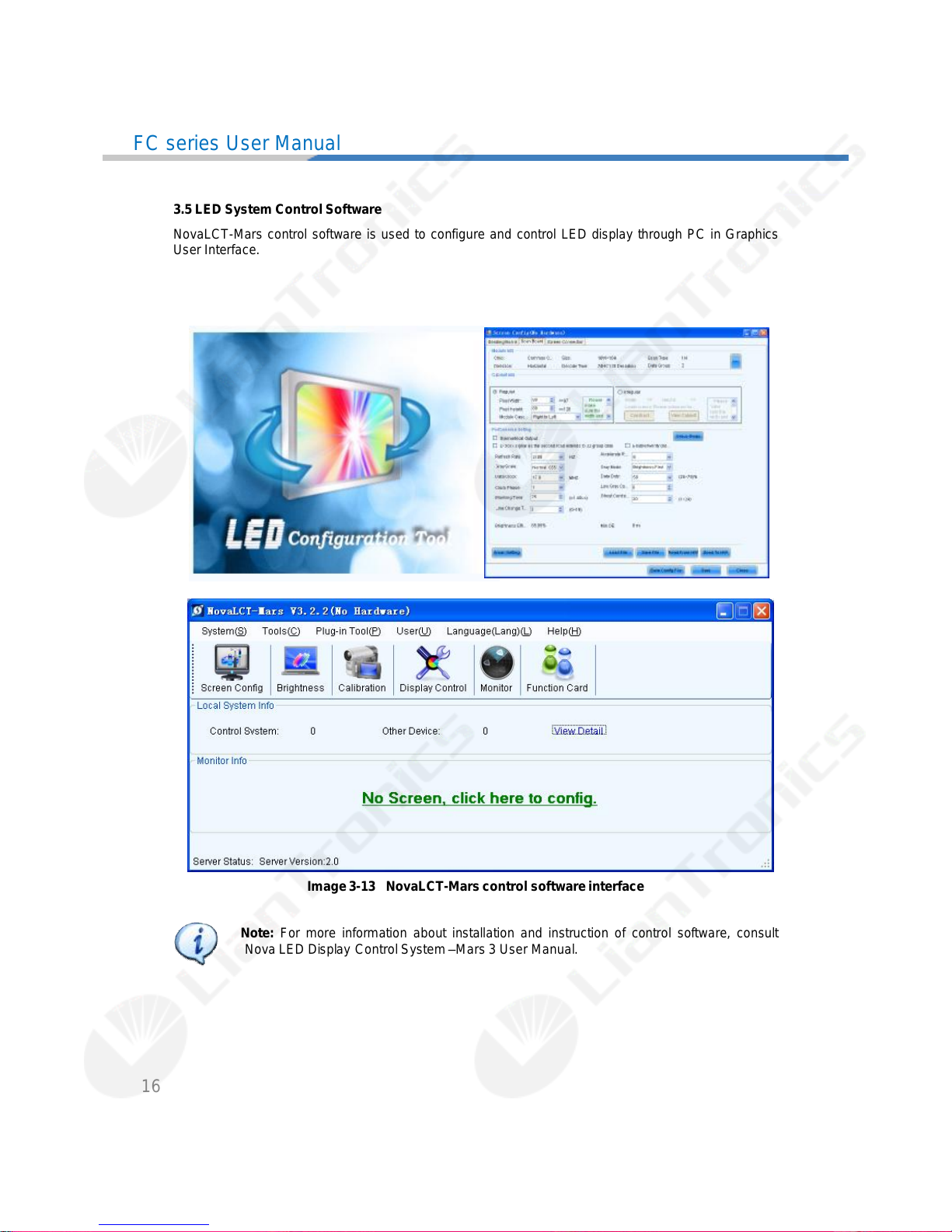
3.5LEDSystemControlSoftware
NovaLCT-MarscontrolsoftwareisusedtoconfigureandcontrolLEDdisplaythroughPCinGraphics
UserInterface.
Image3-13 NovaLCT-Marscontrol software interface
Note: Formoreinformationaboutinstallationandinstructionofcontrolsoftware,consult
NovaLEDDisplayControlSystem –Mars3UserManual.
16
FC series User Manual
Page 21
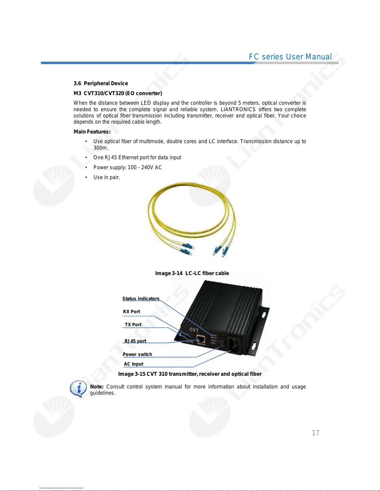
3.6PeripheralDevice
M3CVT310/CVT320(EOconverter)
WhenthedistancebetweenLEDdisplayandthecontrollerisbeyond5meters,opticalconverteris
neededtoensurethecompletesignalandreliablesystem.LIANTRONICSofferstwocomplete
solutionsofopticalfibertransmissionincludingtransmitter,receiverandopticalfiber.Yourchoice
dependsontherequiredcablelength.
MainFeatures:
• Useopticalfiberofmultimode,doublecoresandLCinterface.Transmissiondistanceupto
300m.
• OneRJ45Ethernetportfordatainput
• Powersupply:100-240VAC
• Useinpair.
Image3-14LC-LCfibercable
Image 3-15 CVT 310 transmitter, receiver and optical fiber
Note: Consultcontrolsystemmanualformoreinformationaboutinstallationandusage
guidelines.
17
FC series User Manual
Status indicators
TX Port
RX Port
AC Input
RJ45 port
Power switch
Page 22
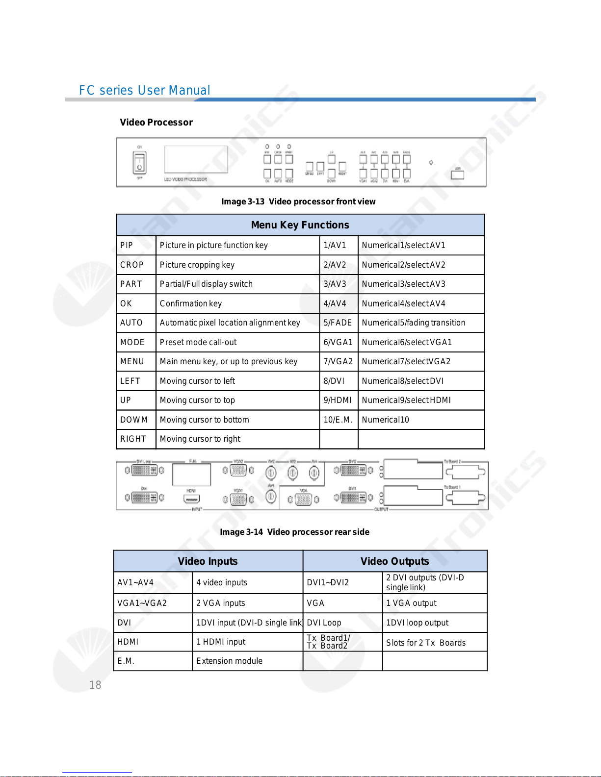
Video Processor
Image 3-13 Video processor front view
Menu Key Functions
PIP Picture in picture function key 1/AV1 Numerical1/select AV1
CROP Picture cropping key 2/AV2 Numerical2/select AV2
PART Partial/Fulldisplay switch 3/AV3 Numerical3/select AV3
OK Confirmation key 4/AV4 Numerical4/select AV4
AUTO Automatic pixel location alignment key 5/FADE Numerical5/fading transition
MODE Presetmode call-out 6/VGA1 Numerical6/select VGA1
MENU Main menu key, or up to previous key 7/VGA2 Numerical7/selectVGA2
LEFT Moving cursor to left 8/DVI Numerical8/select DVI
UP Moving cursor to top 9/HDMI Numerical9/select HDMI
DOWM Moving cursor to bottom 10/E.M. Numerical10
RIGHT Moving cursor to right
Image 3-14 Video processor rear side
VideoInputs VideoOutputs
AV1~AV4 4 videoinputs DVI1~DVI2
2DVI outputs (DVI-D
singlelink)
VGA1~VGA2 2 VGA inputs VGA 1 VGA output
DVI 1DVI input (DVI-D single
link)
DVI Loop 1DVIloop output
HDMI 1 HDMI input
TxBoard1/
TxBoard2
Slotsfor 2 TxBoards
E.M. Extension module
18
FC series User Manual
Page 23
3.7PowerDistributionSystem
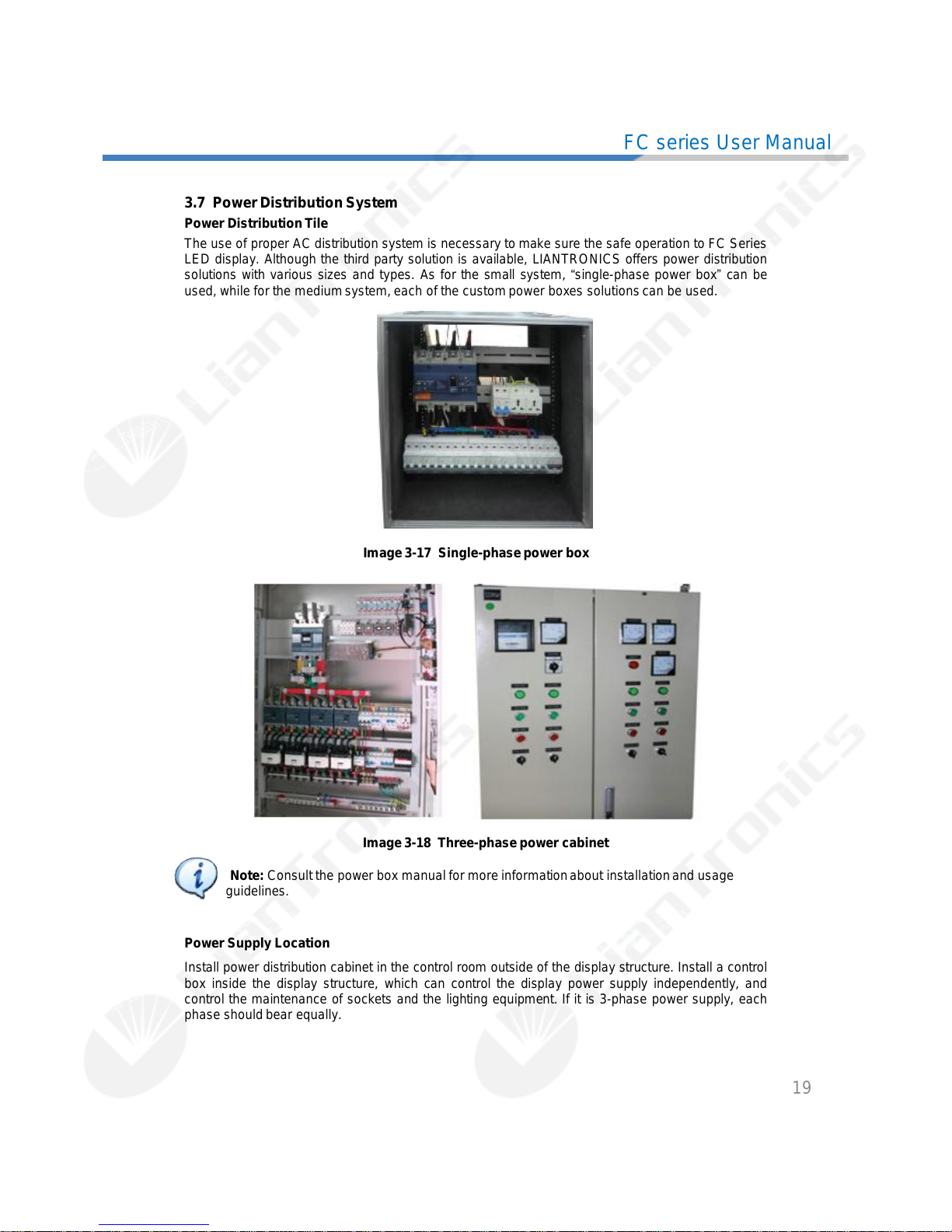
PowerDistributionTile
TheuseofproperACdistributionsystemisnecessarytomakesurethesafeoperationtoFCSeries
LEDdisplay.Althoughthethirdpartysolutionisavailable,LIANTRONICSofferspowerdistribution
solutionswithvarioussizesandtypes.Asforthesmallsystem, “single-phasepowerbox” canbe
used,whileforthemediumsystem,eachofthecustompowerboxessolutionscanbeused.
Note: Consult the power box manual for more information about installation and usage
guidelines.
Power Supply Location
Installpowerdistributioncabinetinthecontrolroomoutsideofthedisplaystructure.Installacontrol
boxinsidethedisplaystructure,whichcancontrolthedisplaypowersupplyindependently,and
controlthemaintenanceofsocketsandthelightingequipment.Ifitis3-phasepowersupply,each
phaseshouldbearequally.
Image3-17Single-phasepowerbox
Image3-18Three-phasepowercabinet
19
FC series User Manual
Page 24
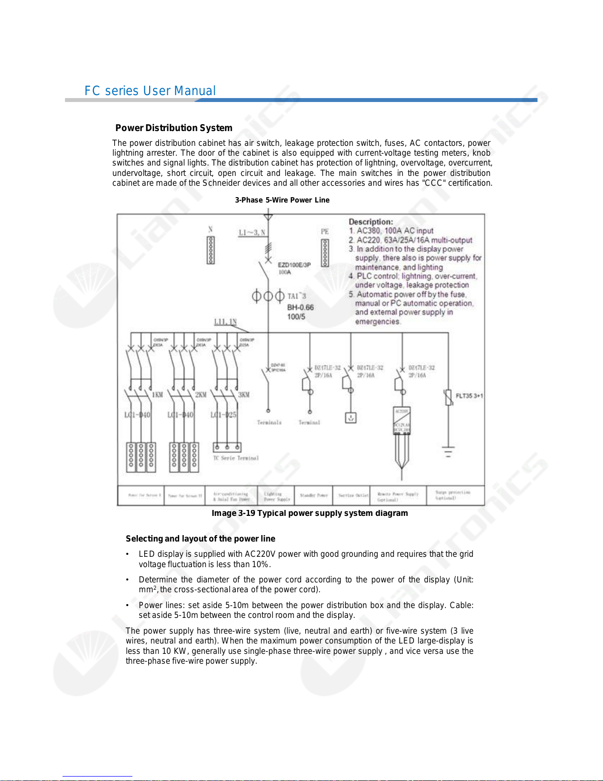
Thepowerdistributioncabinethasairswitch,leakageprotectionswitch,fuses,ACcontactors,power
lightningarrester.Thedoorofthecabinetisalsoequippedwithcurrent-voltagetestingmeters,knob
switchesandsignallights.Thedistributioncabinethasprotectionoflightning,overvoltage,overcurrent,
undervoltage,shortcircuit,opencircuitandleakage.Themainswitchesinthepowerdistribution
cabinetaremadeoftheSchneiderdevicesandallotheraccessoriesandwireshas"CCC"certification.
3-Phase 5-Wire Power Line
Selecting and layout of the power line
• LEDdisplayissuppliedwithAC220Vpowerwithgoodgroundingandrequiresthatthegrid
voltagefluctuationislessthan10%.
• Determinethediameterofthepowercordaccordingtothepowerofthedisplay(Unit:
mm2,thecross-sectionalareaofthepowercord).
• Powerlines:setaside5-10mbetweenthepowerdistributionboxandthedisplay.Cable:
setaside5-10mbetweenthecontrolroomandthedisplay.
Thepowersupplyhasthree-wiresystem(live,neutralandearth)orfive-wiresystem(3live
wires,neutralandearth).WhenthemaximumpowerconsumptionoftheLEDlarge-displayis
lessthan10KW,generallyusesingle-phasethree-wirepowersupply,andviceversausethe
three-phasefive-wirepowersupply.
Image 3-19 Typical power supply system diagram
Power Distribution System
20
FC series User Manual
Page 25

4. SETUP PROCESS
This chapter describes the process of suspended installation and standing installation of FC Series
LED display.
Warning: Safetyfirst.Fenceofftheinstallationareabeforestartingtoinstall.Ensureyou
read,understandandfollowthesafetyinstructionsmentionedinthechapter “Safety” ofthis
installationmanual.Furthermore,makesurethatalltheinstallationrequirementsarefulfilled.
Thetrussbeamandlevelsystemusedinthischapterarepureinstructive,andassumesthetruss
beamandlevelsystemhavebeeninstalledandanswerstotheflatnessrequirements.Thecustomer
isfreetoinstallhisowntrussbeamandlevelsystemaccordingtohisownwishesbutansweringto
themechanicalrequirementsmentionedinthisinstallationmanual.
4.1InstallationPreparation
PackageCheck
• ProductItemNumber —— Confirmed
• Package —— Perfect
• CompleteScreenAppearance —— NoScrape
CabinetOff-lineTest
FCcabinetsupportsoff-linetest.UserscantesteachFCcabinetwithoutconnectingwithLED
controlsystem.Theteststepsareasbelow:
1. MakesurethatthereceivingcardsareconnectedwitheachoftheLEDmodulesbutnot
connectedwithCAT5datacable.
2. TurnontheLEDscreen,thetilesshownothing.
3. Presstheblackswitchonthereceivercardseventimes.ThenthedisplaycontentsontheLED
tilewillbechangedtoDiagonal,Grey,Red,Green,Blue,WhiteandBlackinorder.
Image4-1Off-lineTestbuttononreceivercard
Press this button to change test pattern
21
FC series User Manual
Page 26
Tools Quantity Function
Electric drill 1pc Drill holes on the wall or frame
Rivet drill 1pc Fix the cabinet in place
Electric adhesive plaster Several Isolateelectricity after wire connected
Tape measure 1pc
High-brightness flashlight 1pc Used in the dark area
Safety rope Ref. Personal safety, very important
220V power outlet board 1pc Power supply
Level & vertical ruler 1pc Test the level of the frame
InstallationPreparation
Goodviewingangleandgoodsightforthesurroundings
• Favorableventilationconditions
• Safeandstableratinginputvoltage
• Suitablesize,firmandstableinstallationtable-board
• Rearmaintenancespaceismorethan800mmfromfronttoback.
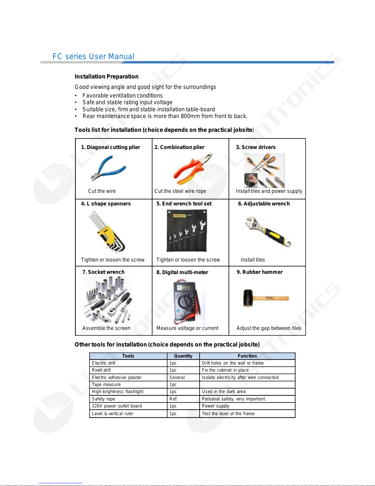
Toolslistforinstallation(choicedependsonthepracticaljobsite)
Other tools for installation (choice depends on the practical jobsite)
1. Diagonal cutting plier
Cut the wire
2. Combination plier
Cut the steel wire rope
3. Screw drivers
Install tiles and power supply
4. L shape spanners
Tighten or loosen the screw
5. End wrench tool set
Tighten or loosen the screw
6. Adjustable wrench
Install tiles
7. Socket wrench
Assemble the screen
8. Digital multi-meter
Measure voltage or current
9. Rubber hammer
Adjust the gap between tiles
22
FC series User Manual
Page 27
4.2 Setup Process of Rear Standing Installation
Warning: TheheightofFCtilesdependsontheheightofsupportingsteelstructureandthe
displaysurfacehastoobtaintheflatnesswithinatolerancezoneof+/-0.2mmandkeep
perpendiculartothereferencesurfaced.
Setup Process
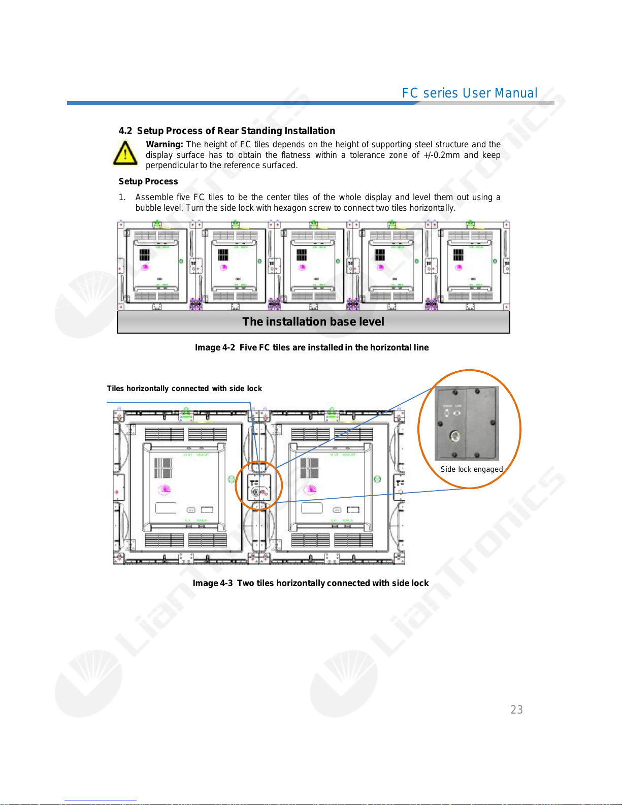
1. AssemblefiveFCtilestobethecentertilesofthewholedisplayandlevelthemoutusinga
bubblelevel.Turnthesidelockwithhexagonscrewtoconnecttwotileshorizontally.
Image 4-2 Five FC tiles are installed in the horizontal line
Image 4-3 Two tiles horizontally connected with side lock
Tiles horizontally connected with side lock
Side lock engaged
The installation base level
23
FC series User Manual
Page 28
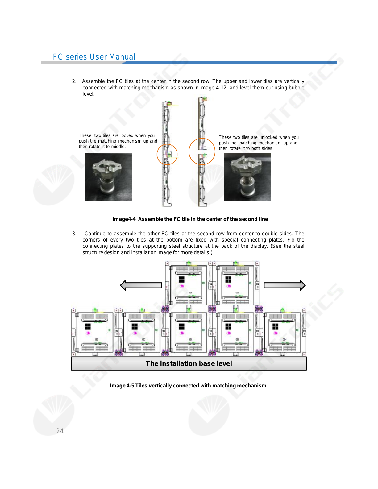
2. AssembletheFCtilesatthecenterinthesecondrow.Theupperandlowertilesarevertically
connectedwithmatchingmechanismasshowninimage4-12,andlevelthemoutusingbubble
level.
Image4-4 Assemble the FC tile in the center of the second line
3. ContinuetoassembletheotherFCtilesatthesecondrowfromcentertodoublesides.The
cornersofeverytwotilesatthebottomarefixedwithspecialconnectingplates.Fixthe
connectingplatestothesupportingsteelstructureatthebackofthedisplay.(Seethesteel
structuredesignandinstallationimageformoredetails.)
Image 4-5 Tiles vertically connected with matching mechanism
The installation base level
Thesetwotilesarelockedwhenyou
pushthematchingmechanismupand
thenrotateittomiddle.
Thesetwotilesareunlockedwhenyou
pushthematchingmechanismupand
thenrotateittobothsides.
24
FC series User Manual
Page 29
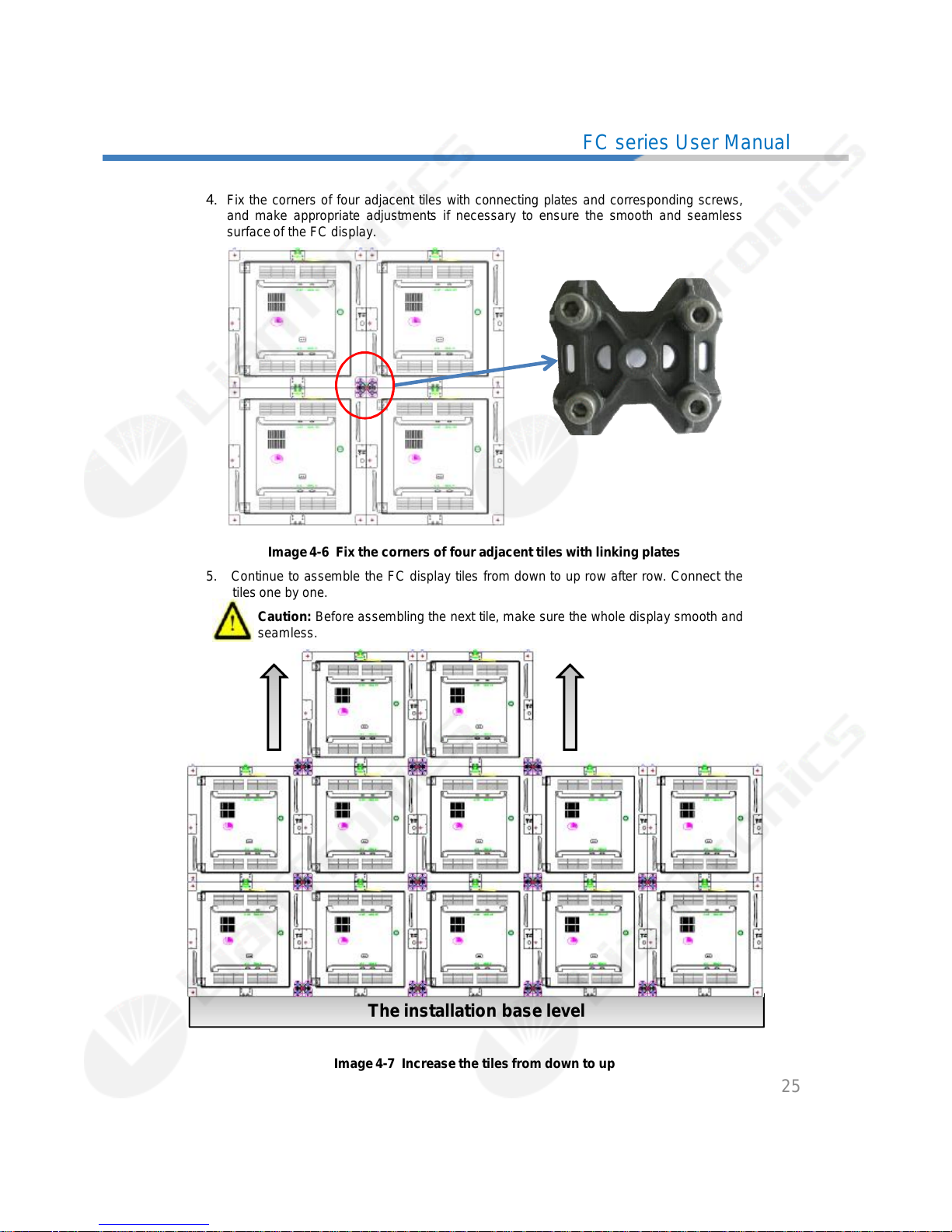
4. Fixthecornersoffouradjacenttileswithconnectingplatesandcorrespondingscrews,
andmakeappropriateadjustmentsifnecessarytoensurethesmoothandseamless
surfaceoftheFCdisplay.
Image 4-6 Fix the corners of four adjacent tiles with linking plates
5. ContinuetoassembletheFCdisplaytilesfromdowntouprowafterrow.Connectthe
tilesonebyone.
Caution: Beforeassemblingthenexttile,makesurethewholedisplaysmoothand
seamless.
Image 4-7 Increase the tiles from down to up
The installation base level
25
FC series User Manual
Page 30
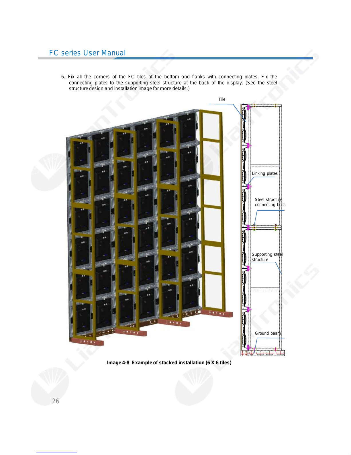
6.FixallthecornersoftheFCtilesatthebottomandflankswithconnectingplates.Fixthe
connectingplatestothesupportingsteelstructureatthebackofthedisplay.(Seethesteel
structuredesignandinstallationimageformoredetails.)
Image 4-8 Example of stacked installation (6 X 6 tiles)
Tile
Linkingplates
Steelstructure
connectingbolts
Supportingsteel
structure
Groundbeam
26
FC series User Manual
Page 31
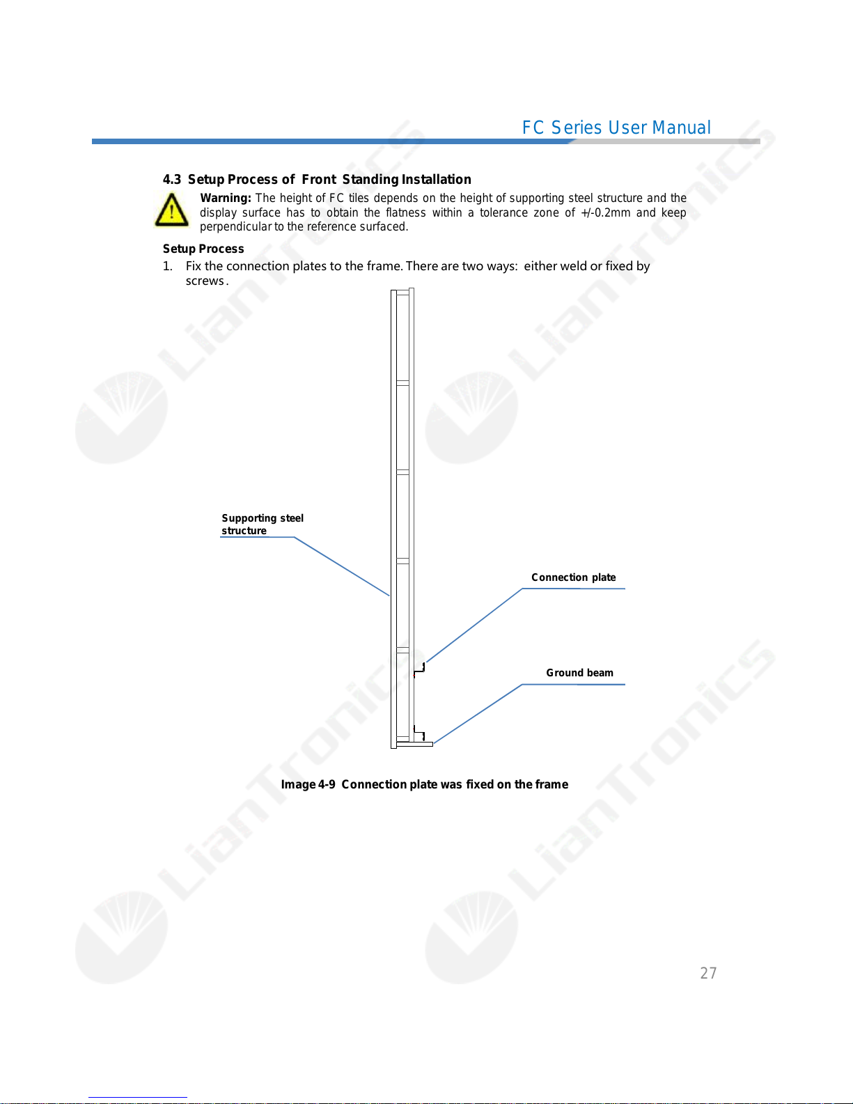
4.3 Setup Process of Front Standing Installation
Warning: TheheightofFCtilesdependsontheheightofsupportingsteelstructureandthe
displaysurfacehastoobtaintheflatnesswithinatolerancezoneof+/-0.2mmandkeep
perpendiculartothereferencesurfaced.
Setup Process
1. Fix the connection plates to the frame. There are two ways: either weld or fixed by
screws .
Image 4-9 Connection plate was fixed on the frame
27
FC Series User Manual
Supportingsteel
structure
Connectionplate
Groundbeam
Page 32
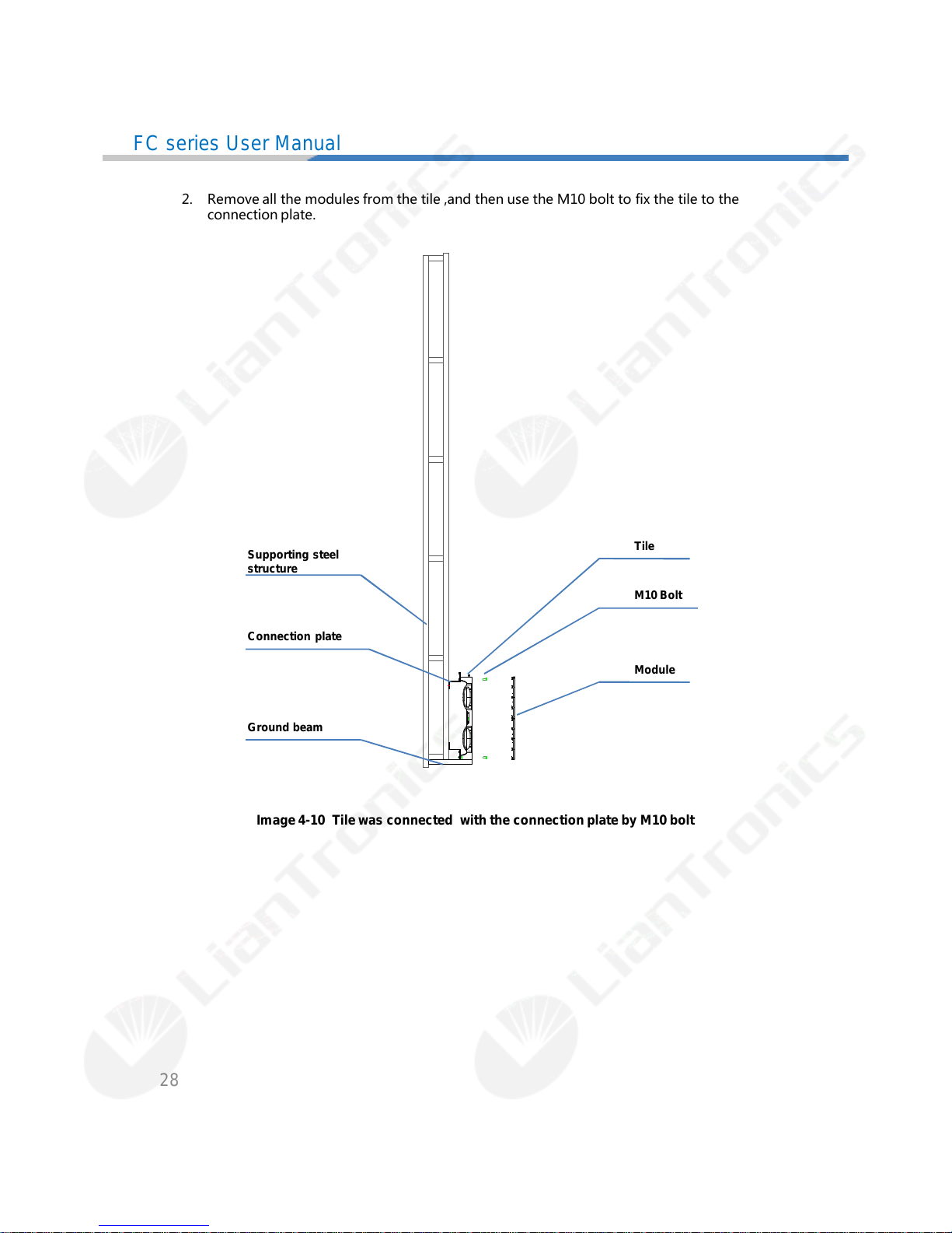
2. Remove all the modules from the tile ,and then use the M10 bolt to fix the tile to the
connection plate.
Image 4-10 Tile was connected with the connection plate by M10 bolt
28
Supportingsteel
structure
Connectionplate
M10Bolt
Module
Tile
Groundbeam
FC series User Manual
Page 33
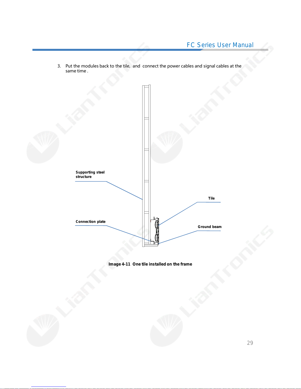
3. Put the modules back to the tile, and connect the power cables and signal cables at the
same time .
Image 4-11 One tile installed on the frame
29
FC Series User Manual
Supportingsteel
structure
Tile
Groundbeam
Connectionplate
Page 34
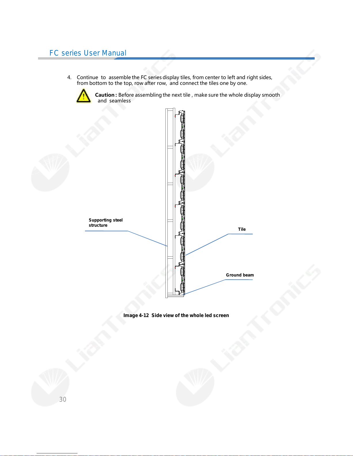
4. Continue to assemble the FC series display tiles, from center to left and right sides,
from bottom to the top, row after row, and connect the tiles one by one.
Caution: Before assembling the next tile , make sure the whole display smooth
and seamless
Image 4-12 Side view of the whole led screen
30
Supportingsteel
structure
Groundbeam
Tile
FC series User Manual
Page 35
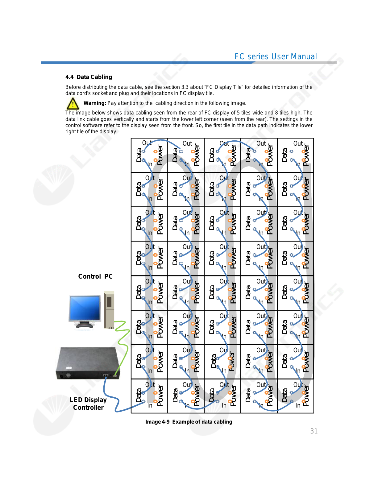
4.4 Data Cabling
Beforedistributingthedatacable,seethesection3.3about “FCDisplayTile” fordetailedinformationofthe
datacord’ssocketandplugandtheirlocationsinFCdisplaytile.
Warning: Pay attention to the cabling direction in the following image.
TheimagebelowshowsdatacablingseenfromtherearofFCdisplayof5tileswideand8tileshigh.The
datalinkcablegoesverticallyandstartsfromthelowerleftcorner(seenfromtherear).Thesettingsinthe
controlsoftwarerefertothedisplayseenfromthefront.So,thefirsttileinthedatapathindicatesthelower
righttileofthedisplay.
Image 4-9Example of data cabling
31
FC series User Manual
Control PC
LED Display
Controller
In
Data
Power
Data
Power
Out
In
Data
Power
Data
Power
Out
In
Data
Power
Data
Power
Out
In
Data
Power
Data
Power
Out
In
Data
Power
Data
Power
Out
In
Data
Power
Data
Power
Out
In
Data
Power
Data
Power
Out
In
Data
Power
Data
Power
Out
In
Data
Power
Data
Power
Out
In
Data
Power
Data
Power
Out
In
Data
Power
Data
Power
Out
In
Data
Power
Data
Power
Out
In
Data
Power
Data
Power
Out
In
Data
Power
Data
Power
Out
In
Data
Power
Data
Power
Out
In
Data
Power
Data
Power
Out
In
Data
Power
Data
Power
Out
In
Data
Power
Data
Power
Out
In
Data
Power
Data
Power
Out
In
Data
Power
Data
Power
Out
In
Data
Power
Data
Power
Out
In
Data
Power
Data
Power
Out
In
Data
Power
Data
Power
Out
In
Data
Power
Data
Power
Out
In
Data
Power
Data
Power
Out
In
Data
Power
Data
Power
Out
In
Data
Power
Data
Power
Out
In
Data
Power
Data
Power
Out
In
Data
Power
Data
Power
Out
In
Data
Power
Data
Power
Out
In
Data
Power
Data
Power
Out
In
Data
Power
Data
Power
Out
In
Data
Power
Data
Power
Out
In
Data
Power
Data
Power
Out
In
Data
Power
Data
Power
Out
In
Data
Power
Data
Power
Out
In
Data
Power
Data
Power
Out
In
Data
Power
Data
Power
Out
In
Data
Power
Data
Power
Out
In
Data
Power
Data
Power
Out
Page 36
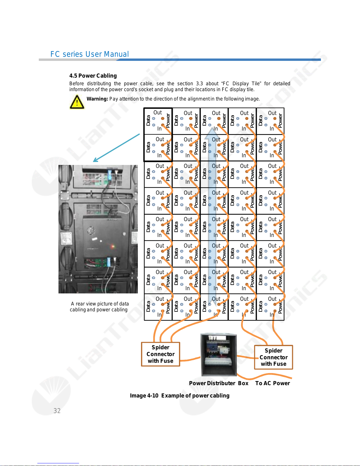
4.5 Power Cabling
Beforedistributingthepowercable,seethesection3.3about “FCDisplayTile” fordetailed
informationofthepowercord’ssocketandplugandtheirlocationsinFCdisplaytile.
Warning: Pay attention to the direction of the alignment in the following image.
Image 4-10 Example of power cabling
In
Data
Power
Data
Power
Out
In
Data
Power
Data
Power
Out
In
Data
Power
Data
Power
Out
In
Data
Power
Data
Power
Out
In
Data
Power
Data
Power
Out
In
Data
Power
Data
Power
Out
In
Data
Power
Data
Power
Out
In
Data
Power
Data
Power
Out
In
Data
Power
Data
Power
Out
In
Data
Power
Data
Power
Out
In
Data
Power
Data
Power
Out
In
Data
Power
Data
Power
Out
In
Data
Power
Data
Power
Out
In
Data
Power
Data
Power
Out
In
Data
Power
Data
Power
Out
In
Data
Power
Data
Power
Out
In
Data
Power
Data
Power
Out
In
Data
Power
Data
Power
Out
In
Data
Power
Data
Power
Out
In
Data
Power
Data
Power
Out
In
Data
Power
Data
Power
Out
In
Data
Power
Data
Power
Out
In
Data
Power
Data
Power
Out
In
Data
Power
Data
Power
Out
In
Data
Power
Data
Power
Out
In
Data
Power
Data
Power
Out
In
Data
Power
Data
Power
Out
In
Data
Power
Data
Power
Out
In
Data
Power
Data
Power
Out
In
Data
Power
Data
Power
Out
In
Data
Power
Data
Power
Out
In
Data
Power
Data
Power
Out
In
Data
Power
Data
Power
Out
In
Data
Power
Data
Power
Out
In
Data
Power
Data
Power
Out
In
Data
Power
Data
Power
Out
In
Data
Power
Data
Power
Out
In
Data
Power
Data
Power
Out
In
Data
Power
Data
Power
Out
In
Data
Power
Data
Power
Out
Power Distributer Box To AC Power
Spider
Connector
with Fuse
Spider
Connector
with Fuse
Arear viewpicture ofdata
cabling and power cabling
32
FC series User Manual
Page 37
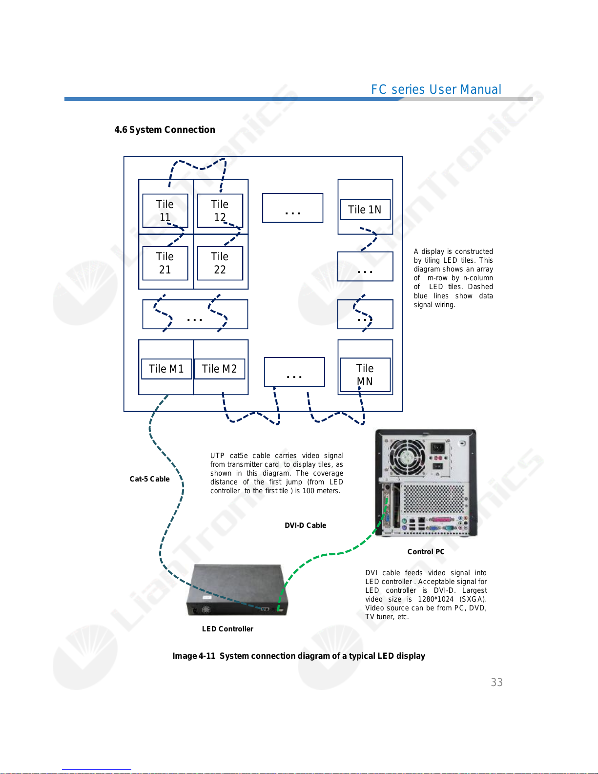
4.6 SystemConnection
Image 4-11 System connection diagram of a typical LED display
Tile
11
…
…
…
Tile
12
Tile
22
Tile
21
Tile 1N
Tile M2Tile M1
Tile
MN
…
…
DVI-DCable
Cat-5Cable
ControlPC
LEDController
Adisplayisconstructed
bytilingLEDtiles.This
diagramshowsanarray
of m-rowbyn-column
of LEDtiles.Dashed
blue lines show data
signalwiring.
DVIcablefeedsvideosignalinto
LEDcontroller.Acceptablesignalfor
LED controller is DVI-D. Largest
videosizeis1280*1024(SXGA).
VideosourcecanbefromPC,DVD,
TVtuner,etc.
UTPcat5ecablecarriesvideosignal
fromtransmittercardtodisplaytiles,as
showninthisdiagram.Thecoverage
distanceofthefirstjump(fromLED
controllertothefirsttile)is100meters.
33
FC series User Manual
Page 38
34
5.START-UPOFTHESYSTEM
5.1SoftwareInstallation
Beforeyourunthesoftware,pleasemakesureallconnectionareready(FromPCtosendingcard,
fromsendingcardtoLEDscreen).PuttheLEDsysteminstallationCDintoCD-ROM.
1.Doubleclick tostartLEDcontrolsoftwareinstallation.
2.Followtheinstallationinstructionuntiltheinstallationprocedurehasfinished.
5.2SystemOperation
First,poweronthecontrolsystemcomputer,andswitchonthepowerofLEDdisplay.followthe
proceduresandinstructionsasbelow:
1.StartNovaLCTcontrolsoftware
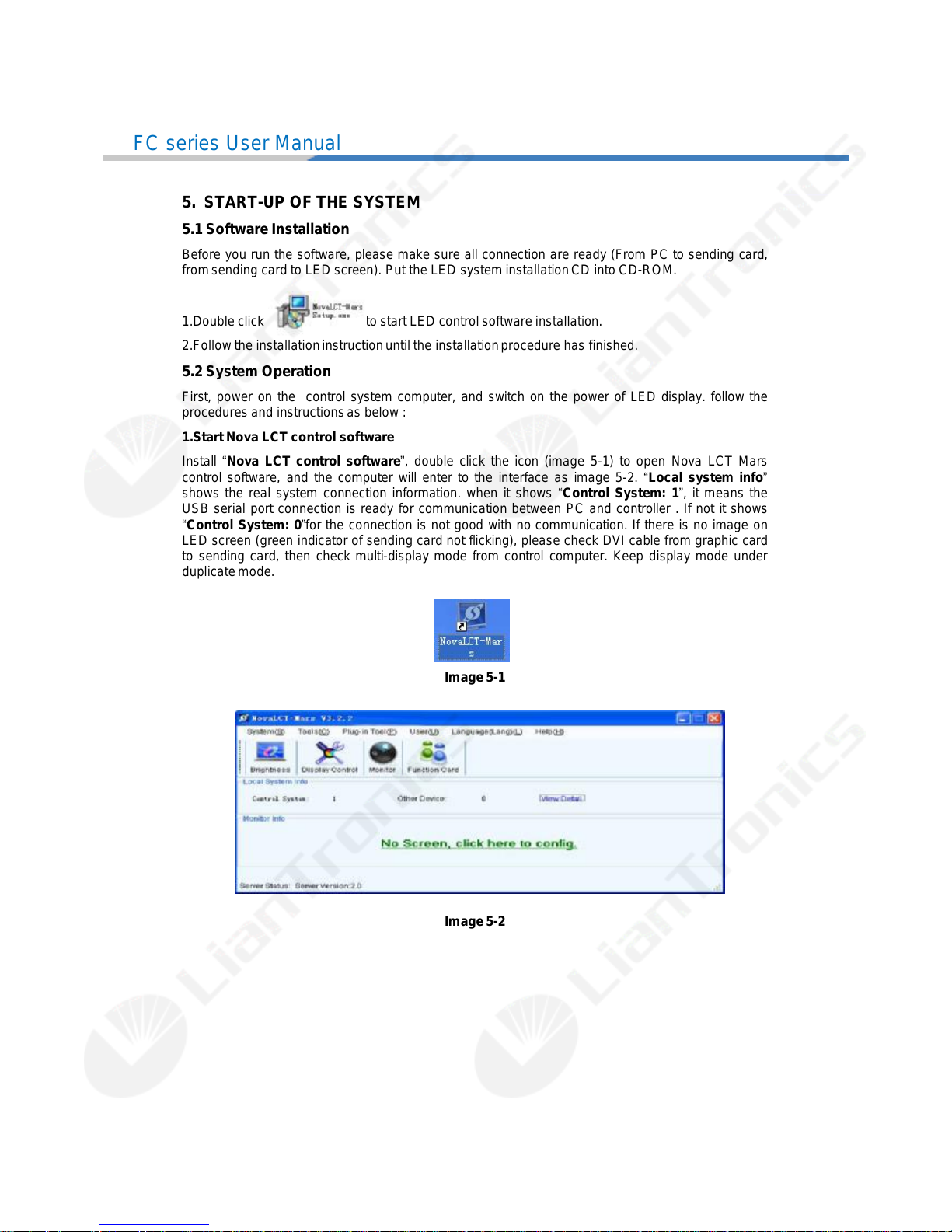
Install “NovaLCTcontrolsoftware”,doubleclicktheicon(image5-1)toopenNovaLCTMars
controlsoftware,andthecomputerwillentertotheinterfaceasimage5-2. “Localsysteminfo”
showstherealsystemconnectioninformation.whenitshows “ ControlSystem:1”,itmeansthe
USBserialportconnectionisreadyforcommunicationbetweenPCandcontroller.Ifnotitshows
“ControlSystem:0”fortheconnectionisnotgoodwithnocommunication.Ifthereisnoimageon
LEDscreen(greenindicatorofsendingcardnotflicking),pleasecheckDVIcablefromgraphiccard
tosendingcard,thencheckmulti-displaymodefromcontrolcomputer.Keepdisplaymodeunder
duplicatemode.
Image 5-1
Image 5-2
FC series User Manual
Page 39
35
FC series User Manual
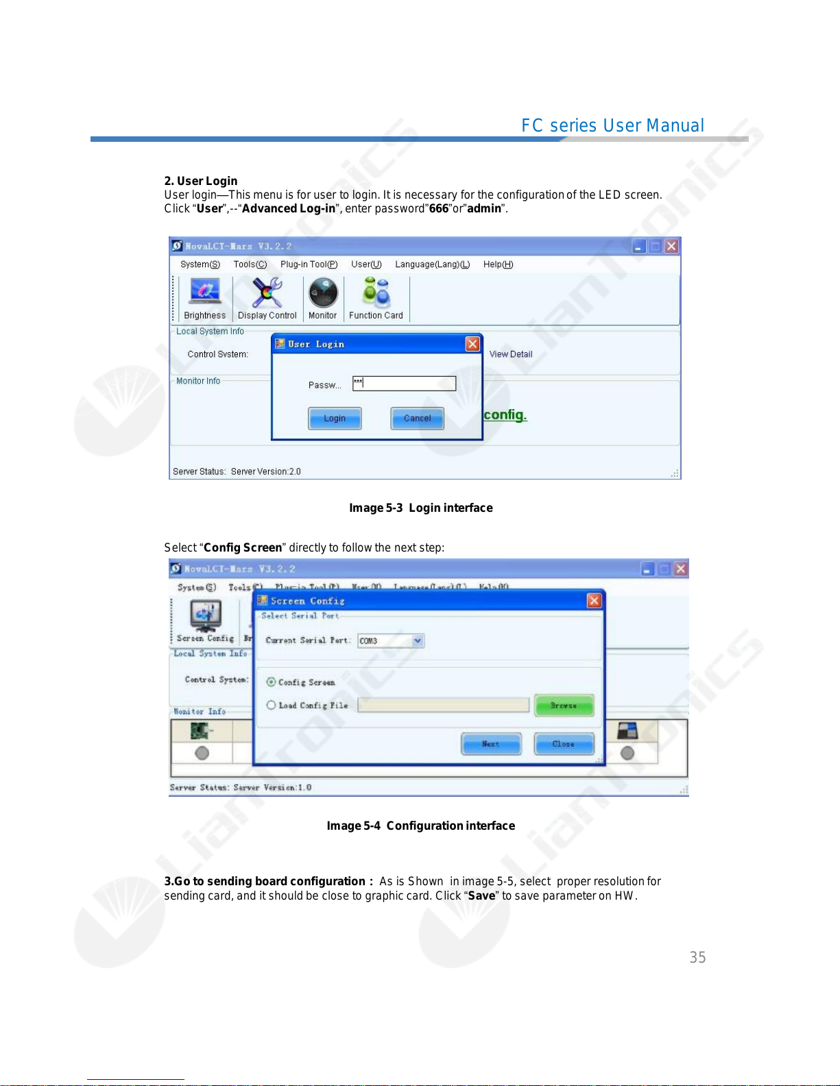
2. User Login
User login—This menu is for user to login. It is necessary for the configuration of the LED screen.
Click “User”,--“Advanced Log-in”, enter password”666”or”admin”.
Image 5-3 Login interface
Select “Config Screen” directly to follow the next step:
Image 5-4 Configuration interface
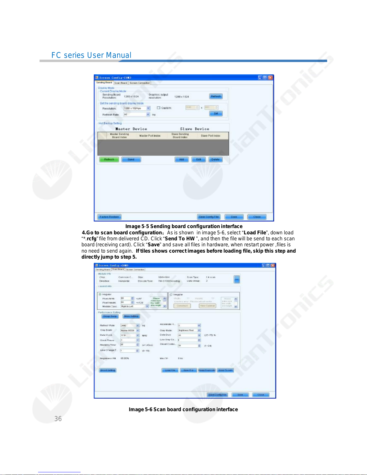
3.Go to sending board configuration: As is Shown in image 5-5, select proper resolution for
sendingcard, and it should be close to graphic card. Click “Save” to save parameter on HW.
Page 40
36
Image 5-5 Sending board configuration interface
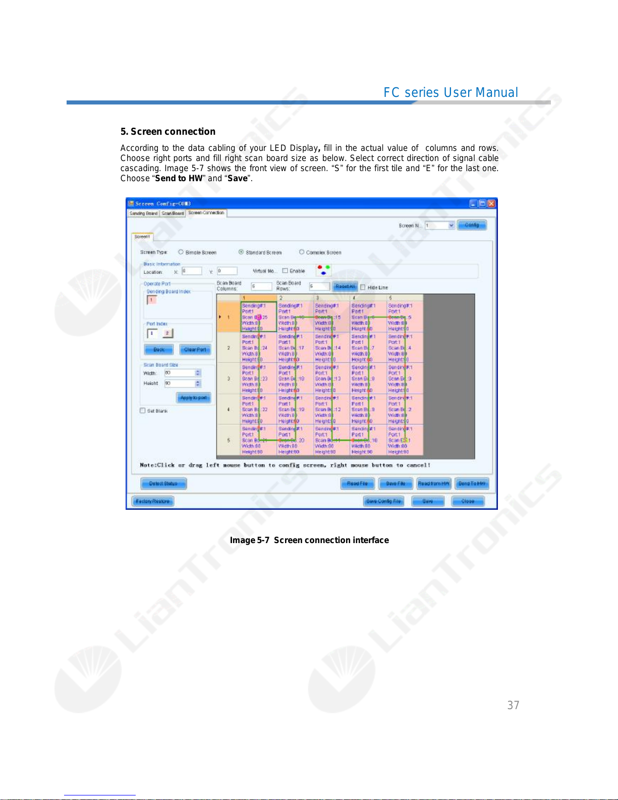
4.Go to scan board configuration:Asis shown in image 5-6, select “Load File”, down load
“*.rcfg” file from delivered CD. Click “Send To HW ”, and then the file will be send to each scan
board (receiving card). Click “Save” and save all files in hardware, when restart power ,files is
no need to send again. If tiles shows correct images before loading file, skip this step and
directly jump to step 5.
Image5-6 Scan board configuration interface
FC series User Manual
Page 41
37
FC series User Manual
5. Screen connection
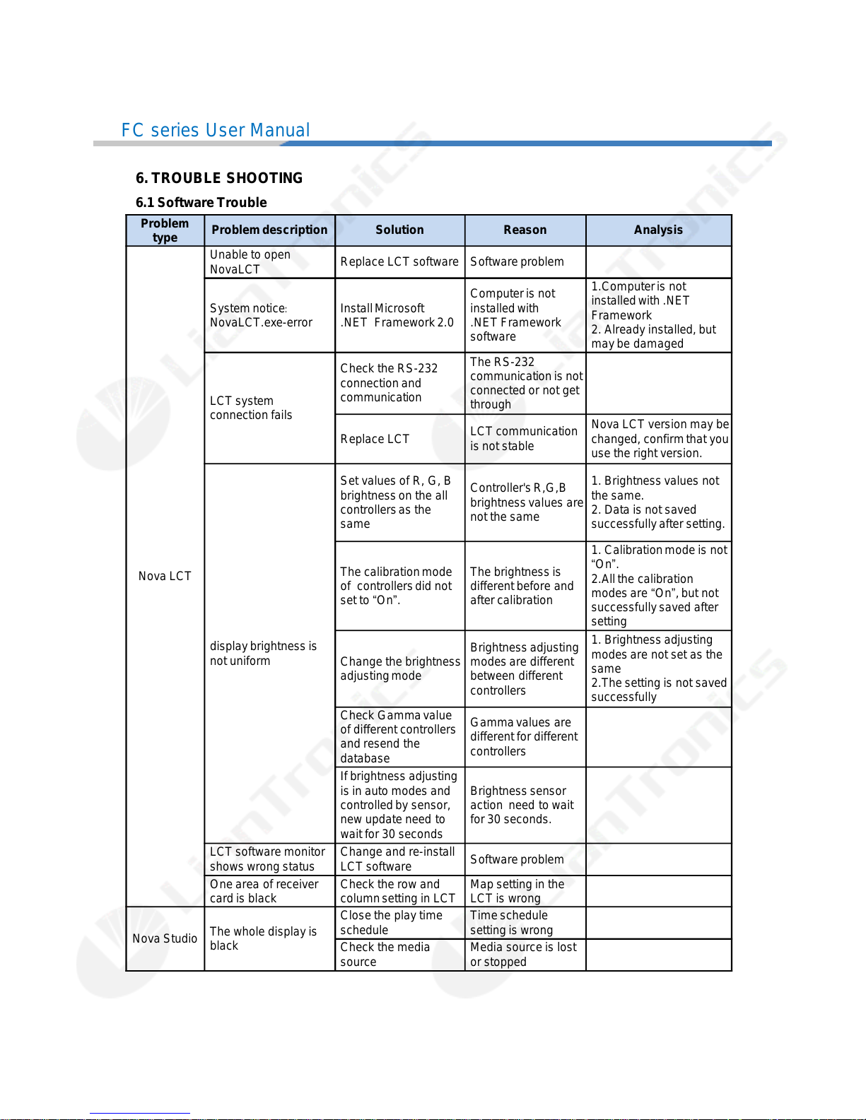
AccordingtothedatacablingofyourLEDDisplay, fillintheactualvalueofcolumnsandrows.
Chooserightportsandfillrightscanboardsizeasbelow.Selectcorrectdirectionofsignalcable
cascading.Image5-7showsthefrontviewofscreen. “S” forthefirsttileand “E” forthelastone.
Choose “SendtoHW” and “Save”.
Image 5-7 Screen connection interface
Page 42
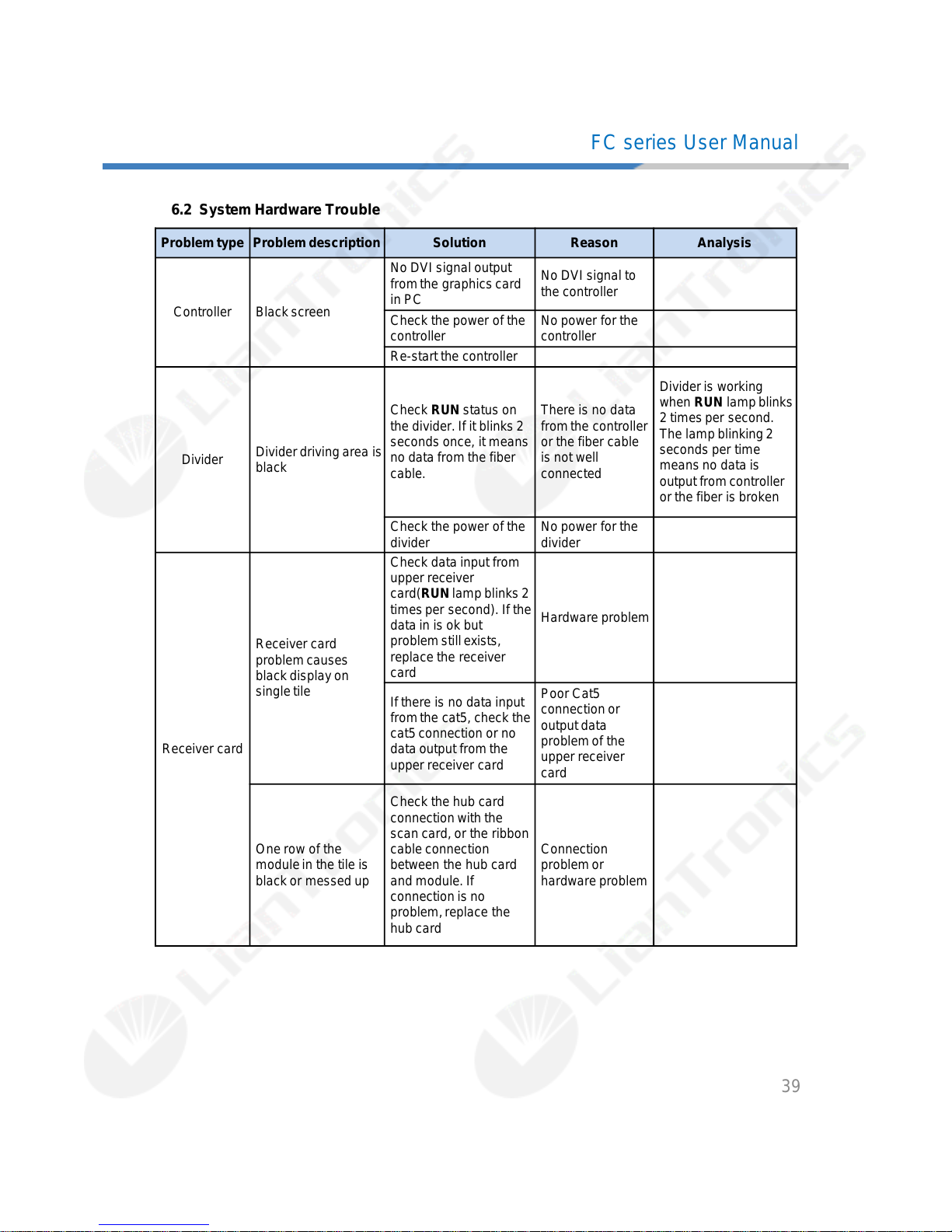
6. TROUBLE SHOOTING
6.1 Software Trouble
38
Problem
type
Problem description Solution Reason Analysis
Nova LCT
Unable to open
NovaLCT
Replace LCT software Software problem
System notice:
NovaLCT.exe-error
InstallMicrosoft
.NETFramework 2.0
Computer is not
installed with
.NETFramework
software
1.Computer is not
installed with .NET
Framework
2. Already installed, but
may be damaged
LCT system
connection fails
Check the RS-232
connection and
communication
The RS-232
communication is not
connected or not get
through
Replace LCT
LCT communication
is not stable
Nova LCT version
may be
changed
, confirm that you
use the right version.
display brightness is
not uniform
Set values of R, G, B
brightness on the all
controllers as the
same
Controller's R,G,B
brightness values are
not the same
1. Brightness values not
the same.
2. Data is not saved
successfully after setting.
The calibration mode
of controllers did not
set to “On”.
The brightness is
different before and
after calibration
1. Calibration mode is not
“On”.
2.All the calibration
modes are “On”, but not
successfully saved after
setting
Change the brightness
adjusting mode
Brightness adjusting
modes are different
between different
controllers
1. Brightness adjusting
modes are not set as the
same
2.The setting is not saved
successfully
Check Gamma value
of different controllers
and resend the
database
Gamma values are
different for different
controllers
If brightness adjusting
is in auto modes and
controlled by sensor,
new updateneed to
wait for 30 seconds
Brightness sensor
action need to wait
for 30 seconds.
LCT software monitor
shows wrong status
Change and re-install
LCT software
Software problem
One area ofreceiver
card is black
Check the row and
column setting in LCT
Map setting in the
LCT is wrong
Nova Studio
The whole display is
black
Close the play time
schedule
Time schedule
setting is wrong
Check the media
source
Media source is lost
or stopped
FC series User Manual
Page 43
6.2 System Hardware Trouble
39
Problem typeProblem description Solution Reason Analysis
Controller Black screen
No DVI signal output
from the graphics card
in PC
No DVI signal to
the controller
Check the power of the
controller
No power for the
controller
Re-start the controller
Divider
Divider driving area is
black
Check RUN status on
the divider. If it blinks 2
seconds once, it means
no data from the fiber
cable.
There is no data
from the controller
or the fiber cable
is not well
connected
Divider is working
when RUN lamp blinks
2 times per second.
The lamp blinking 2
seconds per time
means no data is
output from controller
or the fiber is broken
Check the power of the
divider
No power for the
divider
Receiver card
Receiver card
problem causes
black display on
single tile
Check data input from
upper receiver
card(RUN lamp blinks 2
times per second). If the
data in is ok but
problem still exists,
replace the receiver
card
Hardware problem
If there is no data input
from the cat5, check the
cat5 connection or no
data output from the
upper receiver card
Poor Cat5
connection or
output data
problem of the
upper receiver
card
One row of the
module in the tile is
black or messed up
Check the hub card
connection with the
scan card, or the ribbon
cable connection
between the hub card
and module. If
connection is no
problem, replace the
hub card
Connection
problem or
hardware problem
FC series User Manual
Page 44
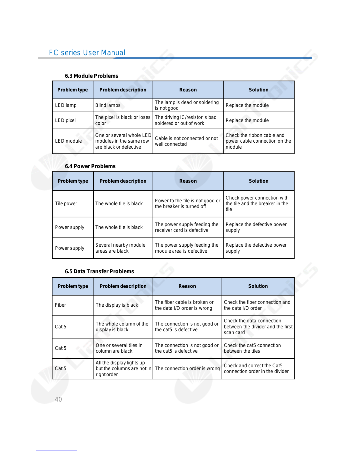
6.3 Module Problems
6.4 Power Problems
6.5 Data Transfer Problems
40
Problem type Problem description Reason Solution
Fiber The display is black
The fiber cable is broken or
the data I/O order is wrong
Check the fiber connection and
the data I/O order
Cat 5
The whole column of the
display is black
The connection is not good or
the cat5 is defective
Check the data connection
between the divider and the first
scan card
Cat 5
One or several tiles in
column are black
The connection is not good or
the cat5 is defective
Check the cat5 connection
between the tiles
Cat 5
All the display lights up
but the columns are not in
right order
The connection order is wrong
Check and correct the Cat5
connection order in the divider
Problem type Problem description Reason Solution
Tile power The whole tile is black
Power to the tile is not good or
the breaker is turned off
Check power connection with
the tile and the breaker in the
tile
Power supply The whole tile is black
The power supply feeding the
receiver card is defective
Replace the defective power
supply
Power supply
Several nearby module
areas are black
The power supply feeding the
module area is defective
Replace the defective power
supply
Problem type Problem description Reason Solution
LED lamp Blind lamps
The lamp is dead or soldering
is not good
Replace the module
LED pixel
The pixel is black or loses
color
The driving IC/resistor is bad
soldered or out of work
Replace the module
LED module
One or several whole LED
modules in the same row
are black or defective
Cable is not connected or not
well connected
Check the ribbon cable and
power cable connection on the
module
FC series User Manual
Page 45
41
FC series User Manual
7 MAINTENANCE
Routinemaintenance
1. MakesuretheLEDdisplayiswellventilated,dryandrunninginsuitabletemperature.
2. RegularlychecktheinternalcablesinsidetheLEDdisplayareinstableconnection,thepower
suppliesareworkingwell,thegroundwiresareconnectedwell,andthelightningarresteris
runningwell.
3. RegularlywipethedustonthesurfaceoftheLEDtilewithasoftcloth,andkeeptheLED
displaysurfacecleantoavoidbrightnessdifferencesbetweencleananduncleanLEDtiles.
Cautionsforuse
1. BeforepowerontheLEDdisplay,startyourcomputerfirst,andthenturnonthepowerofLED
display.
2. Beforeturnoffthedisplaysystem,firstturnoffthepowerofLEDdisplay,andthenturnoffthe
computer.
3. Whenyouareeditingvideoplaylist,youhadbettertokeeptheLEDdisplayclosed.
4. Whenfailureappears,firstturnoffthepowerofLEDdisplay,thencontactwithservice
departmentofLIANTRONICSfortechnicalsupport.
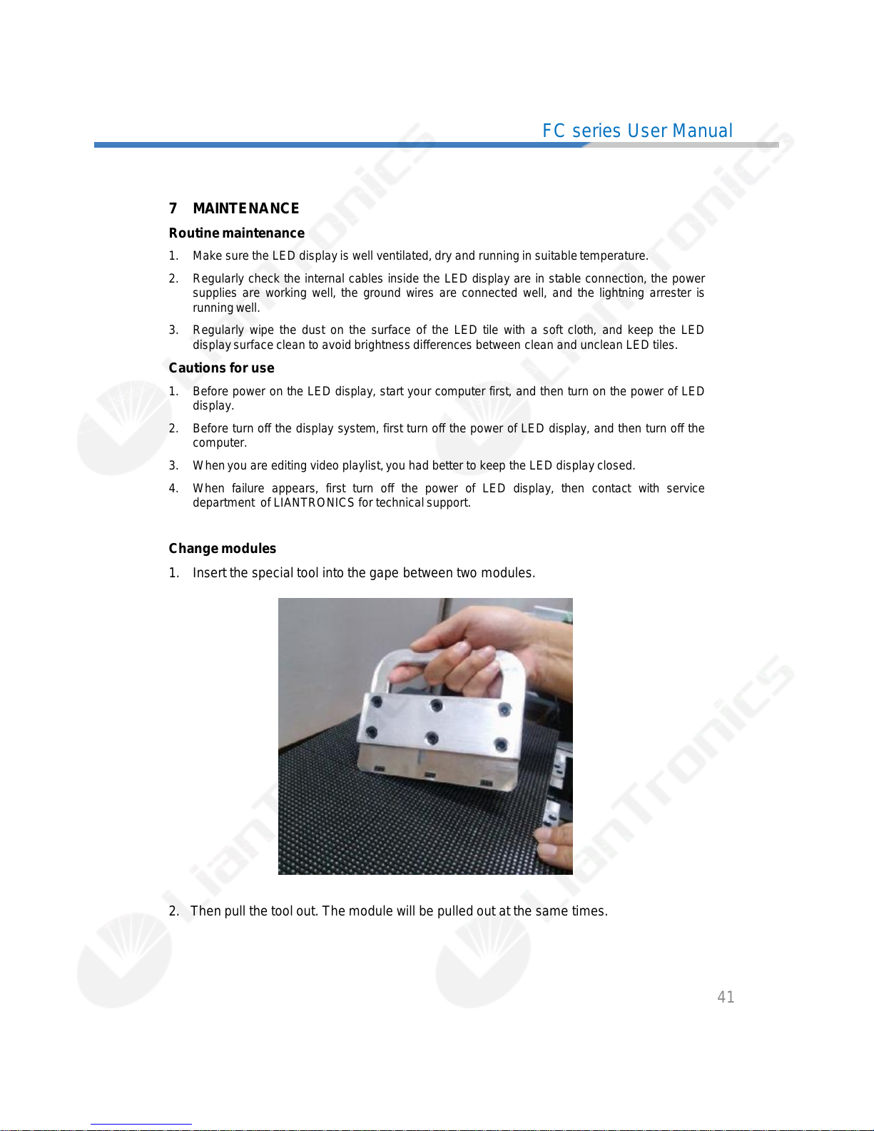
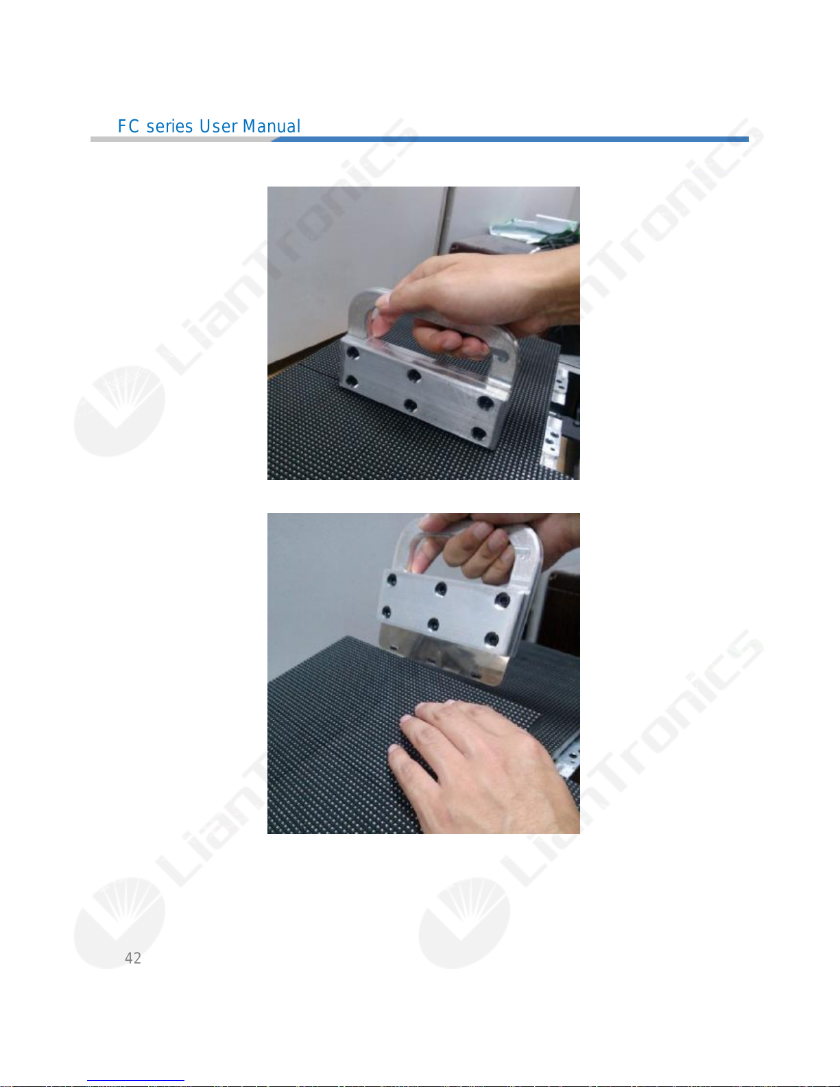
Changemodules
1. Insertthespecialtoolintothegapebetweentwomodules.
2.Thenpullthetoolout.Themodulewillbepulledoutatthesametimes.
Page 46
42
FC series User Manual
Page 47
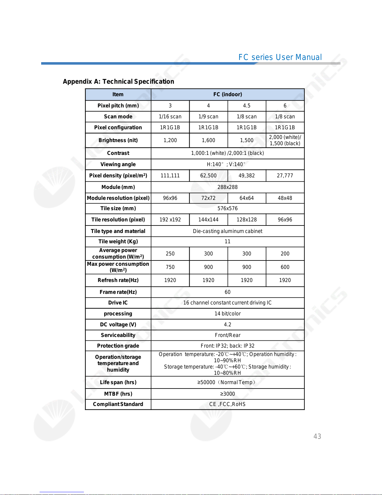
Appendix A:Technical Specification
Item FC (indoor)
Pixel pitch (mm) 3 4 4.5 6
Scan mode 1/16 scan 1/9 scan 1/8 scan 1/8 scan
Pixel configuration 1R1G1B 1R1G1B 1R1G1B 1R1G1B
Brightness (nit) 1,200 1,600 1,500
2,000 (white)/
1,500 (black)
Contrast 1,000:1 (white) /2,000:1 (black)
Viewing angle
H:140°; V:140°
Pixel density (pixel/m2) 111,111 62,500 49,382 27,777
Module (mm) 288x288
Module resolution (pixel) 96x96 72x72 64x64 48x48
Tile size (mm) 576x576
Tile resolution (pixel) 192 x192 144x144 128x128 96x96
Tile type and material Die-casting aluminum cabinet
Tile weight (Kg) 11
Average power
consumption (W/m2)
250 300 300 200
Max power consumption
(W/m2)
750 900 900 600
Refresh rate(Hz) 1920 1920 1920 1920
Frame rate(Hz) 60
Drive IC 16 channel constant current driving IC
processing 14 bit/color
DC voltage (V) 4.2
Serviceability Front/Rear
Protection grade Front: IP32; back: IP32
Operation/storage
temperature and
humidity
Operation temperature: -20℃~+40℃; Operation humidity :
10~90%RH
Storage temperature: -40℃~+60℃; Storage humidity :
10~80%RH
Life span (hrs)
≥50000(Normal Temp)
MTBF (hrs) ≥3000
Compliant Standard CE ,FCC,RoHS
FC series User Manual
43
Page 48
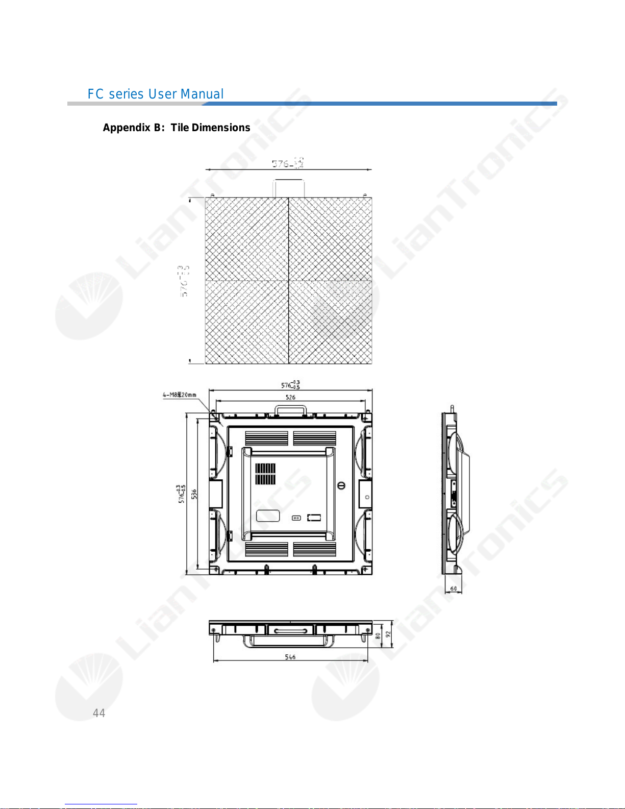
Appendix B:Tile Dimensions
44
FC series User Manual
Page 49
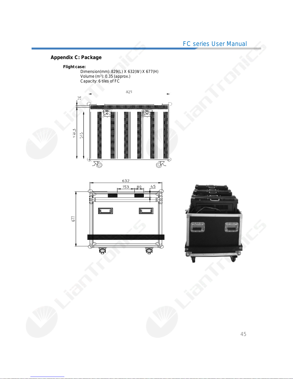
Appendix C:Package
Flight case:
Dimension(mm): 829(L) X 632(W) X 677(H)
Volume (m3): 0.35 (approx.)
Capacity: 6 tiles of FC
FC series User Manual
45
Page 50

 Loading...