

LGX AU95C Series User Manual

1
AU95C Series
Robust Embedded System with
Intel
®
Celeron® 827E Processor
User’s Manual
Version 1.0
2012.11
P/N: 4012165000100P
- i -
Contents
Chapter 1 - General Information .......................................................1
1.1. Introduction ......................................................................................2
1.2. Product Highlights ............................................................................2
1.3. Ordering Information ........................................................................3
1.4. Packing List ......................................................................................4
1.5. Optional Accessory ..........................................................................4
.......................4
...................................................................................6
1.9. Dimensions ......................................................................................8
1.10. External Controls and Connectors .................................................9
Chapter 2 - Engine of the Computer ..............................................11
2.1. Board Layout ..................................................................................12
2.1.1. CPU Board ...........................................................................12
2.1.2. Carrier Board .......................................................................13
2.2. DIP Switches and Connectors .......................................................15
2.2.1. List of DIP Switches and Connectors ..................................15
2.2.2. DIP Switch Setting ...............................................................16
2.2.3. Pin Assignment for Connectors ...........................................20
Chapter 3 - Installation and Maintenance ......................................27
3.1. Remove Bottom Cover ...................................................................28
3.2. Install Wi-Fi Module (Optional) .......................................................29
3.3. Install/Uninstall CFast Card ...........................................................30
3.4. Wall Mount .....................................................................................31
3.5. DIN-Rail Mount ..............................................................................32
3.5.1. Dismount from DIN-rail ........................................................34
3.6. Ground the Computer ....................................................................35
3.7. Wire the DC-Input Power Source ...................................................36
- ii -
Contents
Chapter 4 - BIOS ..............................................................................55
4.1. Main ...............................................................................................58
4.2. Advanced .......................................................................................60
4.2.1. ACPI Settings .......................................................................61
...............................................................62
..............................................................63
............................67
...............................................................68
...............................................................71
4.2.7. H/W Monitor -CPU Board ...................................................72
...........................................72
........................................................75
4.2.10. H/W Monitor -I/O Board ....................................................76
........................................76
4.3. Chipset ...........................................................................................78
........................................79
..........................................................87
4.4. Boot ................................................................................................93
4.5. Security ..........................................................................................94
4.6. Save & Exit ....................................................................................95
Appendix ..........................................................................................97
A: Watchdog Timer (WDT) Setting .......................................................98
4.2.2.
4.2.3.
4.2.4.
4.2.5.
4.2.6.
4.2.8.
4.2.9.
4.2.11.
4.3.1.
4.3.2.

- iii -
Preface
Copyright Notice
All Rights Reserved.
The information in this document is subject to change without prior notice in
order to improve the reliability, design and function. It does not represent a
commitment on the part of the manufacturer .
Under no circumstances will the manufacturer be liable for any direct, indirect,
special, incidental, or consequential damages arising from the use or inability
to use the product or documentation, even if advised of the possibility of such
damages.
This document contains proprietary information protected by copyright. All rights
are reserved. No part of this document may be reproduced by any mechanical,
electronic, or other means in any form withou
t prior written permission of the
manufacturer .
Declaration of Conformity
CE
The CE symbol on your product indicates that it is in compliance with the
by contacting Technical Support.
shielded cables are used for external wiring. We recommend the use of shielded
cables. This kind of cable is available from Logic Supply.
Warning
This is a class A product. In a domestic environment this product may cause
radio interference in which case the user may be required to take adequate
measures.
FCC Class A
This device complies with Part 15 of the FCC Rules. Operation is subject to the
following two conditions:
(1) This device may not cause harmful interference, and
(2) This device must accept any interference received, including interference
that may cause undesired operation.
NOTE:
This equipment has been tested and found to comply with the limits for a
Class A digital device, pursuant to Part 15 of the FCC Rules. These limits are
designed to provide reasonable protection against harmful interference when the

- iv -
Preface
equipment is operated in a commercial environment. This equipment generates,
uses, and can radiate radio frequency energy and, if not installed and used in
accordance with the instruction manual, may cause harmful interference to radio
communications. Operation of this equipment in a residential area is likely to
cause harmful interference in which case the user will be required to correct the
interference at his own expense.
RoHS
The above mentioned directive was published on 2/13/2003. The main purpose
of the directive is to prohibit the use of lead, mercury, cadmium, hexavalent
chromium, polybrominated biphenyls (PBB), and polybrominated diphenyl
ethers (PBDE) in electrical and electronic products. Member
states of the EU are
to enforce by 7/1/2006.
LGX Systems hereby states that the listed products do not contain
unintentional additions of lead, mercury, hex chrome, PBB or PBDB that exceed
a maximum concentration value of 0.1% by weight or for cadmium exceed
a substance or mixture of substances with uniform composition (such as solders,
resins, plating, etc.). Lead-free solder is used for all terminations (Sn(96-96.5%),
Ag(3.0-3.5%) and Cu(0.5%)).
SVHC / REACH
To minimize the environmental impact and take more responsibility to the earth
(Substances of Very High Concern) in (EC) 1907/2006 (REACH --Registration,
Evaluation, Authorization, and Restriction of Chemicals) regulated by the
European Union.
All substances listed in SVHC < 0.1 % by weight (1000 ppm)
LGX Systems certifies that all components in its products are in compliance
and conform to the European Union’s Restriction of Use of Hazardous
Substances in Electrical and Electronic Equipment (RoHS) Directive
2002/95/EC.
LGX
- v -
Preface
Important Safety Instructions
Read these safety instructions carefully
1. Read all cautions and warnings on the equipment.
2. ro ti gnipporD .gnillatsni nehw ecafrus elbailer a no tnempiuqe siht ecalP
letting it fall may cause damage
3. Make sure the correct voltage is connected to the equipment.
4. For pluggable equipment, the socket outlet should be near the equipment
and should be easily accessible.
5. Keep this equipment away from humidity.
6. The openings on the enclosure are for air convection and protect the
equipment from overheating. DO NOT COVER THE OPENINGS.
7. Position the power cord so that people cannot step on it. Do not place
anything over the power cord.
8.
9. eb dluohs tnempiuqe eht ,snosaer ytefas roF .tnempiuqe eht nepo reveN
10. If one of the following situations arises, get the equipment checked by
service personnel:
a. The power cord or plug is damaged.
b. Liquid has penetrated into the equipment.
c. The equipment has been exposed to moisture.
d. The equipment does not work well, or you cannot get it to work according
to the user’s manual.
e. The equipment has been dropped or damaged.
f. The equipment has obvious signs of breakage.
11. Keep this User’s Manual for later reference.

- vi -
Preface
About This User’s Manual
This User’s Manual is intended for experienced users and integrators with
hardware knowledge of personal computers. If you are not sure about any
description in this User’s Manual, please consult your vendor before further
handling.
Warning
The Box PC and its components contain very delicately Integrated Circuits (IC).
To protect the Box PC and its components against damage caused by static
electricity, you should always follow the precautions below when handling it:
1. Disconnect your Box PC from the power source when you want to work on
the inside.
2. Use a grounded wrist strap when handling computer components.
3. Place components on a grounded antistatic pad or on the bag that cam
e
with the Box PC, whenever components are separated from the system.
Lithium Battery Replacement
Incorrect replacement of the lithium battery may lead to a risk of explosion.
The lithium battery must be replaced with an identical battery or a battery type
recommended by the manufacturer .
Do not throw lithium batteries into the trash can. It must be disposed of in
accordance with local regulations concerning special waste.
Technical Support
Please donot hesitate to callor e-mail our customer service when you still cannot
www.logicsupply.com
E-mail: support@logicsupply.com

- vii -
Preface
Warranty
This product is warranted to be in good working order for a period of one year
from the date of purchase. Should this product fail to be in good working order
at any time during this period, we will, at our option, replace or repair it at no
additional charge except as set forth in the following terms. This warranty does
or disaster .
other incidental or consequential damage resulting from the use, misuse of, or
inability to use this product. Vendor will not be liable for any claim made by any
other related party.
Vendors disclaim all other warranties, either expressed or implied, including but
purpose, with respect to the hardware, the accompanying product’s manual(s)
and written materials, and any accompanying hardware. This limited warranty
Return authorization must be obtained from the vendor before returned
merchandise will be accepted. Authorization can be obtained by calling or faxing
the vendor and requesting a Return Merchandise Authorization (RMA) number.
Returned goods should always be accompanied by a clear problem description.
- 1 -
1Chapter 1
General Information
Chapter 1 - General Information
- 2 -
General Information
1.1. Introduction
AU95C is a digital signage player meant for service industry to deliver
AU95C is ideal for the PIS (Passenger Information System) for the mass
transportation services such as train stations and airports. It also brings the
brain for the kiosks in hotels and movie theatres. It is capable of the rich multimedia contents needed for the advertisement screens in the leisure places
such as shopping malls and complexes. The computer is all about hospitality
enhancement and customers touting for your business.
1.2. Product Highlights
All-In-One Platform
The CPU, DRAM and even software are integrated to provide a plug-andplay machine.
Compact-sized
Fanless Design
By using a low power processor, the system does not have to rely on fans,
which are unreliable and often cause dust to circulate inside the equipment.
Modular CPU Board
The modularized CPU board facilitates the possible maintenance or
upgrades to system. Systems based on a modular CPU board can be easily
The boards are based on a non-standard form factor to make the
computer compact enough and consume only a little space.

- 3 -
General Information
Powerful Networking
The AU95C provides multiple COM ports, two Ethernet ports and six
USB ports for data communication.
Numerous Display/Video Output
Integrated with an Intel
®
HD Graphics core, AU95C improves graphics
and 3D rendering performance and supports the display/video output
including DVI-I and HDMI.
Advanced Storage
AU95C comes with an eSATA port for fast data transfer speeds for
external storage device and a CFast-card slot for better, faster and costeffective expansibility for more applications.
Trustworthy
The onboard Watchdog T imer caninvoke an NMI or system reset when your
application misbehaves within the system.
1.3. Ordering Information
AU95C
Barebone system w/ Intel®Celeron 827E
storage and memory
- 4 -
General Information
System Kernel
Processor 1.5GHz or Celeron
™
827E 1.4GHz Processor
BIOS AMI Flash BIOS
Chipset
Intel
®
PCH HM65
Graphics Integrated Intel
®
HD Graphics 3000
Memory
2 x 204-pin SO-DIMM sockets, supporting DDR3
1066/1333 MHz up to 8GB SDRAM
SerialATA 1 x SerialATA port with 600MB/s HDD transfer rate
Ethernet Controller
1 x Intel
®
82579LM Gigabit Ethernet controller
w/ iAMT 7.0
1 x Intel®82583V Gigabit Ethernet controller
Watchdog Timer 1 ~ 255 levels reset
I/O Ports
Serial Port
4 x COM ports RS-232
2 x COM ports RS-232/485
Expansion Bus 1 x Mini-card slot for optional WiFi module
USB Port 6 x USB 2.0 ports
LAN 2 x RJ-45 ports for Gigabit Ethernet
Video Port
1 x DVI-I receptacle for Digital Video output
1 x HDMI female connector for Digital Video output
Audio Mic-in, Line-out
External
SAT
A 1 x eSATA port
Storage
Type
1 x 2.5” drive bay for HDD/SSD
1 x outside accessible CFast socket
FCC
CE
Environmental
Operating Temp.
Storage Temp. -40 ~ 85ºC (-40 ~ 185ºF)
Relative Humidity 5 ~ 95% @ 40°C (non-condensing)
- 5 -
General Information
Vibration 1 Grms/5~500Hz/random operation, CFast, 1G/SDD
Shock
Operating 40G (11ms), Non-operating80G with SSD
Operating 20G (1 1ms), Non-operating 60G with HDD
Mechanical
Construction Aluminum alloy
Mounting DIN-rail mount & wall mount
Weight 2.87 kg (6.32 lb) (Bare-bone)
Dimensions
(W x D x H)
228.5 x 155 x 65 mm (8.99” x 6.10” x 2.55”)
Power Requirement
Power Input DC 9-32V input
Power
Consumption
Max. 38W
- 6 -
General Information
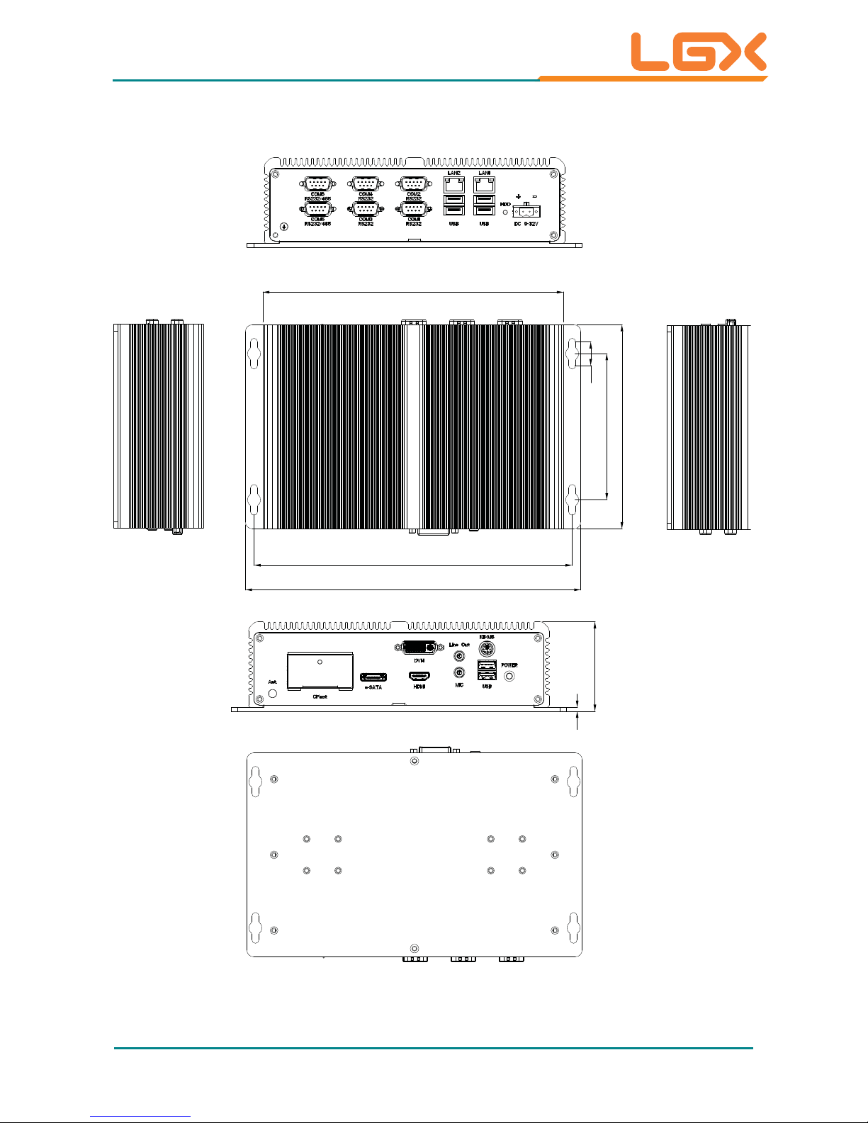
1.9. Dimensions
3
68
241.8
254.8
228.5
18
155
111.1
Unit: mm
- 7 -
General Information
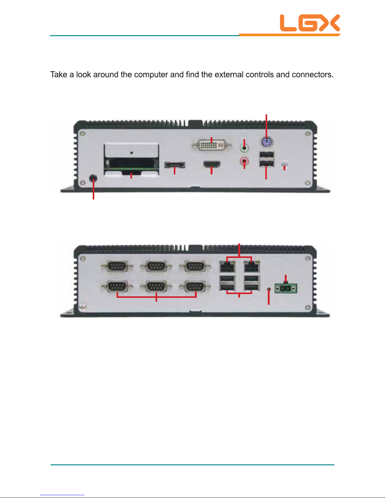
1.10. External Controls and Connectors
Front View
MIC-in
HDMI
eSATA
CFast
Line-out
DVI-I
Antenna Hole
PWR Button
USB Ports
KB/MS
Rear View
HDD LED
USB Ports
COM Ports
LAN Ports
DC-IN

- 8 -
2Chapter 2
Engine of the
Computer
Chapter 2 - Engine of the Computer
- 9 -
Engine of the Computer
2.1. Board Layout
The CPU board and the carrier board together form the engine of the AU95C.
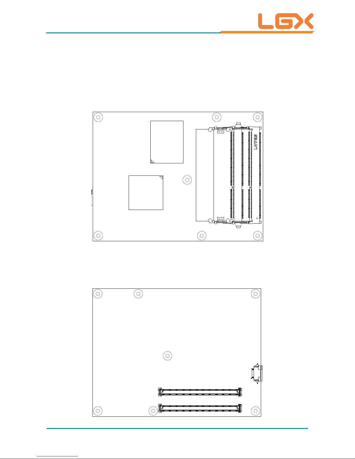
2.1.1. CPU Board
Top View
Sandy
Bridge
Processor
PCH
QM67/HM65
Bottom View
COM Express®AB Connector
COM Express®CD Connector
COM Express CD Connector
COM Express AB Connector
- 10 -
Engine of the Computer
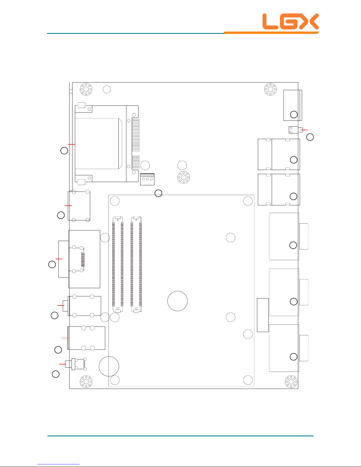
2.1.2. Carrier Board
PBC-9004: Board Top
B110
A110
B1
A1
EH3
D110
C110
D1
C1
19
1
PC17
PC1
S7
S1
PW1
KBUSB1
AUDIO2
CN3
ESATA1
CF1
LED1
COM C
COM B
COM A LAN2 LAN1
PWRIN1
COM Express AB Connector
COM Express CD Connector
3
3
4
5
5
6
7
8
10
12
13
9
11
14
CPUF1
- 11 -
Engine of the Computer
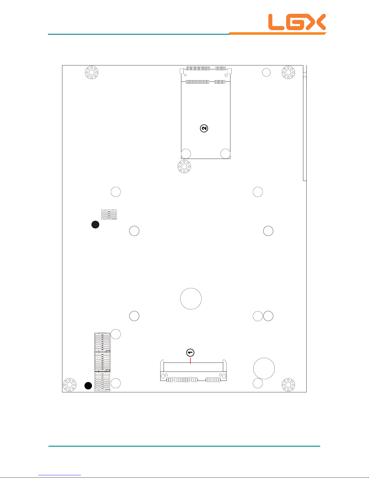
PBC-9004: Board Bottom
P15
P1S7
S1
52
51
16 18
15 17
2
1
SATA1
MC1
1
12345678
ON
9
169
SW1 SW2 SW3
2
1
123456781234
5678
ON
16
ON
16 9
1234
5678
ON
SW4

- 12 -
Engine of the Computer
2.2. DIP Switches and Connectors
2.2.1. List of DIP Switches and Connectors
DIP Switches
Board
Side
No. Label Function
Bottom
ᆺ
SW4
Clears/keeps CMOS setting
Selects the BIOS from the CPU board or carrier
board.
Switches power supply between AT and ATX modes.
Bottom
ᆻ
SW1~3 Sets COM5~6 to RS-232 or RS-485.
Connectors
Board
Side
No. Label Description
Bottom
SATA1 SerialATA connectors
Bottom
ཱ
MC1 Mini-card interface connector
Top
ི
COM A/B COM1~4 RS-232 serial ports
Top
ཱི
COM C COM5~6 RS-232/485 serial ports
Top
ུ
LAN1~2 Ethernet connectors (including USB connectors)
Top
ཱུ
CF1 CFast slot
Top
ྲྀ
ESATA1 External serialATA connector
Top
ཷ
CN3 HDMI and DVI-I connectors
Top
ླྀ
AUDIO2 Audio jack connector (line-out/mic-in)
Top
ཹ
KBUSB1 PS/2 keyboard and mouse (including USB
connectors)
Top
ེ
PW1 Power button
Top
ཻ
PWRIN1 DC power input
Top
ོ
LED1 HDD status LED
Top
ཽ
CPUF1 CPU fan connector
- 13 -
Engine of the Computer
2.2.2. DIP Switch Setting
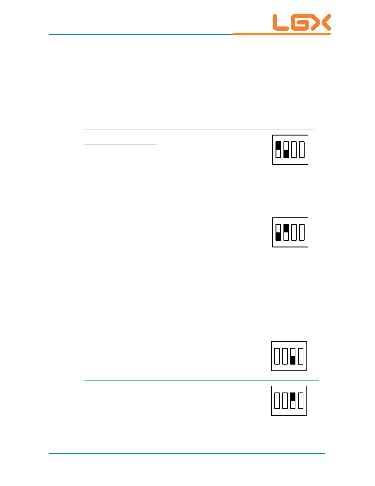
2.2.2.1. SW4
ᆺ: Clears/Keeps CMOS Setting
The SW4 is a 8-pin and 4-toggle switch. It relies on its toggles 1 and 2 to
clear/keep the CMOS setting of the computer.
SW4
Toggle Position Function Setting
1On
Keeps CMOS setting
(default)
1234
ON
KE
Toggle
2Off
SW4
Toggle Position Function Setting
1Off
Clears CMOS setting
1234
ON
KE
Toggle
2On
2.2.2.2. SW4
ᆺ: Sets Power Supply Mode
It relies on SW4’s toggles 3 to switch the power supply mode between AT
and A TX modes.
SW4
Toggle Position Function Setting
3Off
Sets the power supply to
ATX mode (default)
1234
ON
KE
Toggle
3On
Sets the power supply to
AT mode
1234
ON
KE
Toggle
- 14 -
Engine of the Computer
2.2.2.3. SW4
ᆺ: Selects BIOS from CPU Board / Carrier Board
It relies on SW4’s toggle 4 to select the BIOS from either the CPU board or the
carrier board.
SW4
Toggle Position Function Setting
4On
Selects the BIOS from the
CPU board
1234
ON
KE
Toggle
4Off
Selects the BIOS from te
carrier boards (default)
1234
ON
KE
Toggle
2.2.2.4. SW1, SW3 ᆻ: COM5 Data Transmission Interface Setting
It relies on SW1 and SW3 to set the data transmission interface for COM5. T o set
COM5 to RS-232 or RS-485, apply the following setting:
Ź RS-232 (Default)
SW1
Toggle Pins
Position
Setting
1 1 & 16 On
12345678
16 15 14 13 12 11 10 9
ON
KE
2 2 &15 On
3 3 & 14 On
4 4 & 13 On
5 5 & 12 On
6 6 & 11 On
7 7 & 10 On
8 8 & 9 On
SW3
Toggle Pins
Position
Setting
1 1 & 16 On
12345678
16 15 14 13 12 11 10 9
ON
KE
22 &15Off
3 3 & 14 Off
4 4 & 13 Off
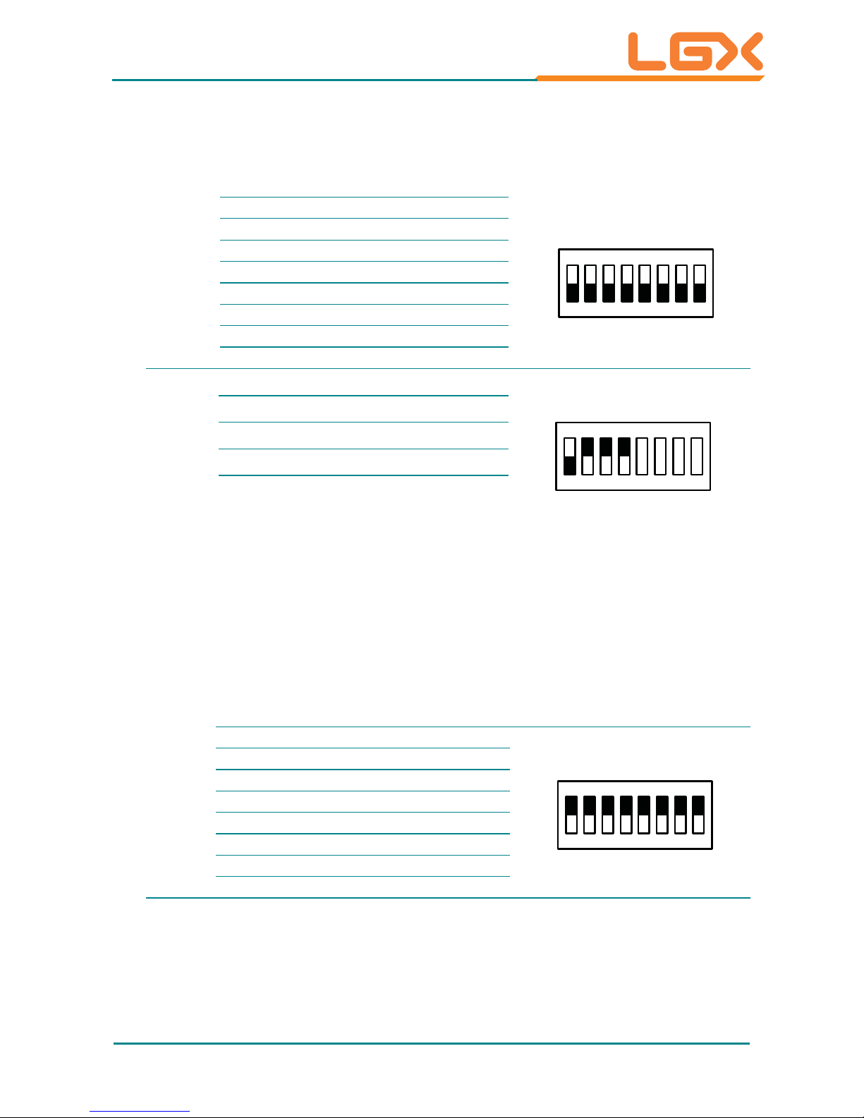
- 15 -
Engine of the Computer
Ź RS-485
SW1
Toggle Pins
Position Setting
1 1 & 16 Off
12345678
16 15 14 13 12 11 10 9
ON
KE
22 &15Off
3 3 & 14 Off
4 4 & 13 Off
5 5 & 12 Off
6 6 & 11 Off
7 7 & 10 Off
88 & 9Off
SW3
Toggle Pins
Position
Setting
1 1 & 16 Off
12345678
16 15 14 13 12 11 10 9
ON
KE
2 2 &15 On
3 3 & 14 On
4 4 & 13 On
2.2.2.5. SW2, SW3
ᆻ: COM6 Data Transmission Interface Setting
It relies on SW2 and SW3 to set the data transmission interface for COM6. T o set
COM6 to RS-232 or RS-485, apply the following setting:
Ź RS-232 (Default)
SW2
Toggle Pins
Position
Setting
1 1 & 16 On
12345678
16 15 14 13 12 11 10 9
ON
KE
2 2 &15 On
3 3 & 14 On
4 4 & 13 On
5 5 & 12 On
6 6 & 11 On
7 7 & 10 On
8 8 & 9 On
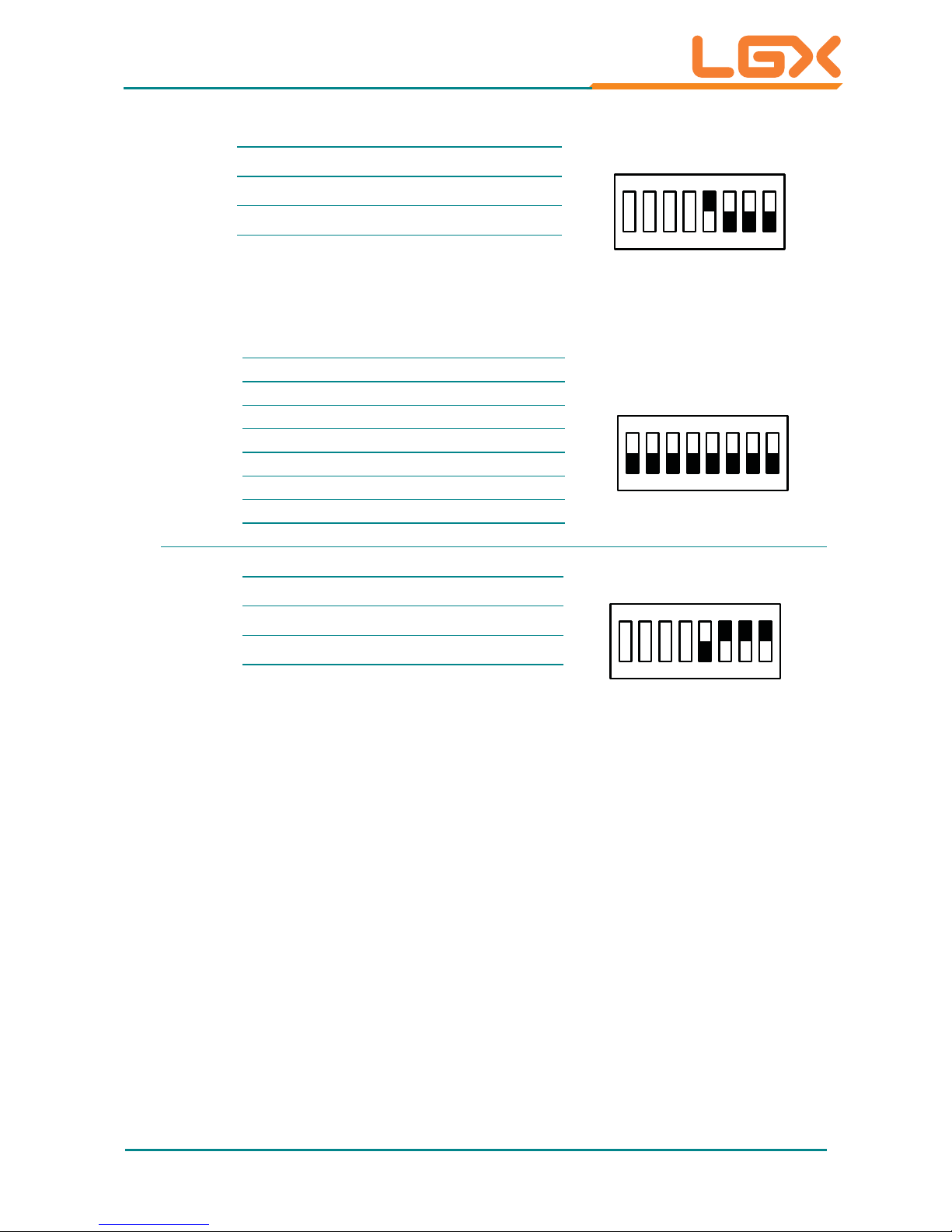
- 16 -
SW3
Toggle Pins
Position
Setting
5 5 & 12 On
12345678
16 15 14 13 12 11 10 9
ON
KE
6 6 & 11 Off
7 7 & 10 Off
88 & 9Off
Ź RS-485
SW2
Toggle Pins
Position Setting
1 1 & 16 Off
12345678
16 15 14 13 12 11 10 9
ON
KE
22 &15Off
3 3 & 14 Off
4 4 & 13 Off
5 5 & 12 Off
6 6 & 11 Off
7 7 & 10 Off
88 & 9Off
SW3
Toggle Pins
Position
Setting
5 5 & 12 Off
12345678
16 15 14 13 12 11 10 9
ON
KE
6 6 & 11 On
7 7 & 10 On
8 8 & 9 On
- 17 -
Engine of the Computer
2.2.3. Pin Assignment for Connectors
PWRIN1
ཻ: DC Power Input
Pin Description
DC IN
9 - 32V
+
-
1
2
1 PWRIN1_VCC
2C-GND
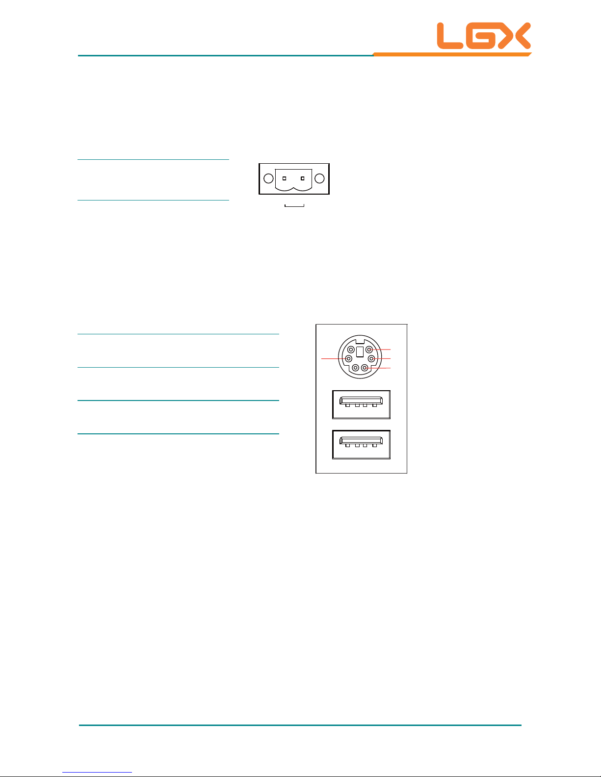
KBUSB1
ཹ: PS/2 Keyboard and USB Stacked Connectors
Connector type: 6-pin Mini-DIN/Stacked USB type A connector
USB Pin Description
KB_VCC
KB_CLK
KB_GND
KB_DA T
1234
1234
1+5V
2USB-
3USB+
4GND

- 18 -
Engine of the Computer
LAN1~2
ུ: LAN + USB Stacked Connectors
This connector supports USB 2.0 x 2 (USB0, 1) & 10/100Mbps or Gigabit RJ-45
Ethernet connection.
LAN (RJ-45)
Pin Description
LAN
USB
USB
1234
81
1234
1MDI0+
2MDI03MDI1+
4MDI15MDI2+
6MDI27MDI3+
8MDI3-
USB (Type A Connector)
Pin Description
1+5V
2 USB3 USB+
4GND
AUDIO2
ླྀ: Audio Jacks
The jacks support HD ‘97 audio. The green jack is line-out jack while the pink
one is the mic-in.
Pin Description
Line-out
MIC-in
5
1
1GND
2R
3 HP-IN
4GND
5L
 Loading...