

Page 1
Global LCD Panel Exchange Center
Module
www.panelook.com
MODEL : LP141WP1 - TLA1
CAUTION
BEFORE SERVICING THE MODULE, READ THE SAFETY PRECAUTIONS
IN THIS MANUAL.
[ Lead Free ]
One step solution for LCD / PDP / OLED panel application: Datasheet, inventory and accessory!
www.panelook.com
Page 2
Global LCD Panel Exchange Center
Review the following safety precautions to avoid injury and prevent damage to this product or any products connected to it.
To avoid potential hazards, use this product only as specified.
Only qualified personnel should perform service procedures.
LCD Module is a display device to be divided into Board Ass’y and Backlight Ass’y. Board Ass’y consists of electric circuitry,
PCB and two sheets of glass. Polarizer films are attached on each surface. The space between two sheets of glass are filled
with Liquid Crystal. And the Backlight Ass’y includes Lamp Ass’y, optical sheets(Diffuser, Prism), LGP(Light Guide Panel),
supporter main.
When using / handing this LCD Module, pay attention to the below warning and cautions.
www.panelook.com
SAFETY PRECAUTIONS
Warning?
Warning statements identify conditions or
practices that could result in injury or loss of life
if the warning is ignored and the product is
handled incorrectly.
Caution?
Caution statements identify conditions or
practices that could result in damage to this
product or other property if the caution is
ignored and the product is handled
incorrectly.
WARNING
(1) Do not supply a voltage higher than that specified to this
product. This may damage the product and may cause a
fire.
(3) Do not install or use the product in a location that dose not
satisfy the specified environmental conditions. This may
damage the product and may cause a fire.
(4) If a foreign substance (such as water, metal, or liquid)gets
inside the product, immediately turn off the power.
Continuing to use the product and cause fire or electric
shock.
(5) If the product emits smoke or abnormal noise, immediately
turn off the power. Continuing to use the product cause fire
or electric shock.
(6) Do not disconnect or connect the connector while the
power is on.
(7) Do not pull out or insert the power cable from/to an outlet
with wet hands. It may cause electric shock.
(8) If the power cable is damaged or the connector is loose, do
not use the product : otherwise this can lead to fire or
electric shock.
(9) Backlight Inverter uses a high voltage for Lamp. Do not
touch circuit substrate and caution on electric shock when
handling the LCD Module Backlight Inverter unit.
(2) Do not use this product in locations where the humidity is
extremely high, where it may be splashed with water, or
where flammable materials surround it.
One step solution for LCD / PDP / OLED panel application: Datasheet, inventory and accessory!
www.panelook.com
Page 3
Global LCD Panel Exchange Center
www.panelook.com
English
Korean
CAUTION
(1) Do not place this product in a location that is subject to
heavy vibration, or an unstable surface such as an inclined
surface. The product may fall off or fall over, causing
injuries.
(2) Before disconnecting cable from the product, be sure to
turn off the power. Be sure to hold the connector when
disconnecting cables. Pulling a cable with excessive force
may cause the core of the cable to be exposed or break
the cable, and this can lead to fire or electric shock.
(3) This product contains glass. If shock, vibration, heat or
distortion is applied to the product, the glass may be broken.
(4) If glass surface of the display breaks or is scratched, do
not touched the broken pieces or the scratched with bare
hands. You may be injured.
(5) LCD Module requires to be handled with special care. LCD
Module is not to be touched with metal or hard materials.
Must not be stressed by heat or mechanical impact.
(6) There are some particular components on the rear panel of
this product. Skin contact with these components may
cause an electric shock. So, handle with care.
(7) While moving the product, be sure to turn off the power,
disconnect all cables and watch your step. Dropping the
product may cause injuries from electric shock. So, while
moving the product handle with care.
(8) When cleaning the panel is necessary, wipe it with a soft
and moistened cloth a neural detergent. Caution on
connector area. Do not use chemicals such as thinner or
benzene.
(9) LCD Module emits heat from the Lamp, Backlight lamp,
component parts. Therefore, the environmental
temperature must not exceed 50
Inverter system is driven by high voltage, so it must avoid
conductive materials.
(10) If repairing components with a lead line, high voltage or
high temperature components must be put out from a
lead line and fix.
(11) Do not place an object on the surface of the display. The
glass may break or be scratched.
(12) This product may be damaged if it is subject to excessive
stresses (such as excessive voltage, current, or
temperature). The absolute maximum ratings specify the
limits of these stresses.
(13) Do not cover or wrap with any covering materials while
power is applied to the product.
(14) This product is made from various material such as glass,
metal, and plastic. When discarding it, be sure to contact
a purchase place.
(15) If a discrepancy occurs due to any arbitrary modification
or disassembly, LG.Philips LCD is not responsible for
function, quality or other items.
(16) Within the warranty period, general faults may be charged
for depending on responsibility for the faults. You handle
with care.
. LCD Module Backlight
One step solution for LCD / PDP / OLED panel application: Datasheet, inventory and accessory!
www.panelook.com
Page 4
Global LCD Panel Exchange Center
SERVICING PRECAUTIONS
Color TFT LCD Module is apt to be damaged by both electrical and mechanical stresses.
Users, therefore, are requested to follow the “Servicing precautions of color TFT LCD Module” on the followings.
www.panelook.com
System Assembler
(1) Follow power sequence.
Abnormal power sequence may cause critical malfunction
or electrical damage.
(2) Prevent physical stress.
(3) Prevent overheat.
High temperature on the surface of the screen may cause
poor quality. Please make LCD Module used on specified
temperature.
Low temperature under 10 makes LCD Module respond
slowly, make Backlight worse operated and shorten very
much the lifetime accordingly.
(4) Keep LCD Module dust-free.
LCD Module is sensitive against dust.
Dust can cause visual or functional problem.
(5) Do not touch TCP area.
Do not touch TCP area at any case. It causes Driver IC
crack, film crack etc. TCP is the weakest point of LCD
Module.
(6) Do not pull Backlight wire.
Please do not pull the Backlight wire it can cause the wire
disconnected or damaged.
(7)Check a connection of the Inverter & Backlight
connectors.
Incomplete connection with can cause burnt in Backlight
connector or damage the inverter.
(8) Handle with care.
Please do not drop, bend or hit the LCD Module. Physical
stress can cause the defect such as broken.
(9) Keep mounting screw length and motor driver’s torque.
Strong weaken motor driver’s torque can make a
mechanical defect on LCD Module. Please keep the
specification.
(10) Do not operate for a long time under the same pattern.
Operating LCD Module for a long time under the same
pattern can cause image persistence and can damage it.
(11) Defect panel also handled with care.
To prevent making another defect, please handle the
defective LCD Module as a good one.
Defective LCD Module should be repaired.
(12) Do not stack LCD Modules.
LCD Module consists of fragile components such as TCPs
or Glasses.
Stacking LCD Module can cause undesired defects.
One step solution for LCD / PDP / OLED panel application: Datasheet, inventory and accessory!
www.panelook.com
Page 5

Global LCD Panel Exchange Center
www.panelook.com
English
Korean
(13) Do not provide strong pressure at connecting.
Strong pressure can transfer the force to TCP which is the
weakest parts of LCD Module. Eventually can make TCP
crack or other unexpected defect.
(14) Let the Backlight Wire backside of LCD Module.
If let the Backlight wire front side of LCD Module, the
Backlight connector can hurt the surface of polarizer.
System Assembler/End User
(1) Keep clean the surface.
Please wear rubber glove when touch the surface of LCD
Module screen.
Please use soft and anti-static material with n-Hexane as
cleaner.
(2) Be careful not to make polarizer scratch.
Surface of polarizer is soft, so it’s easily scratched.
Please do not touch, press or rub on polarizer surface with
materials over HB hardness.
(3) Be careful swift Temperature & Humidity change.
Swift temperature and or humidity change can make dew
condensation or ice which cause nonconformance such as
malfunction.
(15) Never connect/disconnect at power on.
LCD Module consists of CMOS which is known as weak
component against EOS. It can hurt the product.
(16) Electro-static discharge can make damage.
Semi-assembled product should be handled with wrist strap.
Earth human body when handle the LCD Module.
Please do not touch the interface connector pin.
(4) Keep out of water.
Water on in the LCD Module can cause electrical short or
corrosion.
Please wipe out or dry water carefully.
(5) Keep LCD Module corrosive gases free.
Corrosive gas makes the polarizer and the circuitry parts
chemical damages and eventually cause defects.
(6) Keep the suitable temp. & suitable humidity.
High temp. & high humidity shorten the lifetime.
One step solution for LCD / PDP / OLED panel application: Datasheet, inventory and accessory!
www.panelook.com
Page 6
Global LCD Panel Exchange Center
www.panelook.com
CONTENTS
1. Product Overview
2. Module Formation
3. Exploded View
4. Exploded View Parts List
5. Block Diagram
6. Trouble shooting
7. Timing Check Sheet
8. Disassembly
9. Assembly
10. Parts List
11. Records of Revision
12. Derivative description
Annexing : Schematic Diagram / Printed Circuit Board
*
.......................................................
.......................................................
............................................
...........................................
..............................................
..............................
...............................................
............................................
.......................................
..................................................
.......................................
....................................
7
8
10
11
12
13
18
19
23
29
32
33
One step solution for LCD / PDP / OLED panel application: Datasheet, inventory and accessory!
www.panelook.com
Page 7
Global LCD Panel Exchange Center
General Description
TFT-LCD is made up of the lower plate glass with TFT, the upper plate glass with color filter, the middle
Liquid Crystal. TFT convey and control the signal and the Liquid Crystal control transmitted ray as
molecular structure different by admitted volt. And as the ray pass color filter, show up the wanted color
and picture.
The LP141WP1-TLA1 is 14.1 inches diagonally measured active display area with WXGA+ resolution(900
vertical by 1440 horizontal pixel array). Each pixel is divided into Red, Green and Blue sub-pixels or dots
which are arranged in vertical stripes. Gray scale or the brightness of the sub-pixel color is determined with
a 6-bit gray scale signal for each dot, thus, presenting a palette of more than 262,144 colors.
The LP141WP1-TLA1 has been designed to apply the interface method that enables low power, high speed,
low EMI.
The LP141WP1-TLA1 is intended to support applications where thin thickness, low power are critical
factors and graphic display are important. In combination with the vertical arrangement of the sub-pixels,
the LP141WP1-TLA1 characteristics provide an excellent flat display for office automation products such
as Notebook PC.
www.panelook.com
English
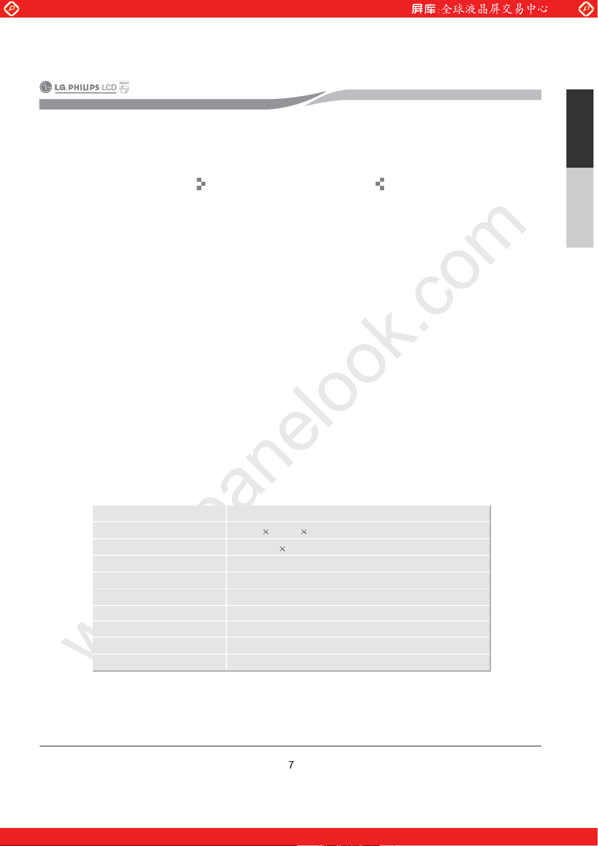
1. Product Overview
Korean
Active Screen Size
Outline Dimension
Pixel Pitch
Pixel Format
Color Depth
Luminance, White
Power Consumption
Weight
Display Operating Mode
Surface Treatment
General Features
14.1 inches diagonal
320(H)
0.2109 mm
1440 horiz. By 900 vert. Pixels RGB strip arrangement
6-bit, 262,144 colors
220 cd/m
Total 6.0 Watt(Typ.)
435g (Max.), 425g(Typ.)
Transmissive mode, normally white
Anti-glare treatment of the front polarizer
206(V) 5.5(D, max)mm
0.2109 mm
2
(Typ. 5point)
One step solution for LCD / PDP / OLED panel application: Datasheet, inventory and accessory!
www.panelook.com
Page 8
Global LCD Panel Exchange Center
* Connector 1(CN1) : User Connector
www.panelook.com
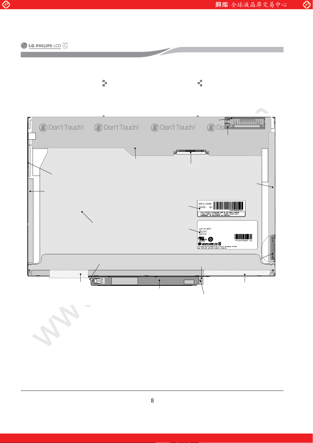
2. Module Formation
Source COF(D-IC)
Source PCB
Case Ass’y
Adhesive Tape
Backlight Wire
Fixed Tape
Backlight Ass’y
Backlight Wire
Cover Shield(Source)
Backlight Label
Inverter
* Connector 1(CN1)
ID Label
Inverter Bracket
Inverter Fixed Screw
Cover Shield(Gate)
Gate COF(COF)
Adhesive Tape
One step solution for LCD / PDP / OLED panel application: Datasheet, inventory and accessory!
www.panelook.com
Page 9
Global LCD Panel Exchange Center
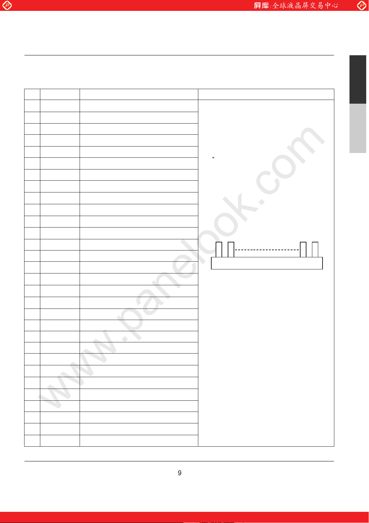
Module Connector Pin configuration(CN1)
www.panelook.com
NO
1
2
3
4
5
6
7
8
9
10
11
12
13
14
15
Symbol
GND
VCC
VCC
V EEDID
BIST
Clk EEDID
DATA EEDID
RA1-
RA1+
GND
RB1-
RB1+
GND
RC1-
RC1+
Description
Ground
Power Supply, 3.3V Typ.
Power Supply, 3.3V Typ.
DDC 3.3V power
Reserved for LCD supplier test point
DDC Clock
DDC Data
Negative LVDS differential data input,R0-G5,G0
Positive LVDS differential data input,R0-G5,G0
Ground
Negative LVDS differential data input,G1-G5,B0-B1
Positive LVDS differential data input,G1-G5,B0-B1
Ground
Negative LVDS differential data input,B2-B5,HS/VS/DE
Positive LVDS differential data input,B2-B5,HS/VS/DE
Notes
1. Interface chips
1.1 LCD : DAWIN,DTML012(LCD Controller)
including LVDS Receiver
(DAWIN co., LVD4107 x 2each)
1.2 System : It must include international standard
LVDS Trasmitter.
Pin to Pin compatible with LVDS
2. Connector
2.1 LCD : GT101-30S-HR11,LGC or its compatibles.
2.2 Mating : FI-X30M or equivalent.
2.3 Connector Pin arrangement
[LCD Module Rear View]
30 1
English
Korean
16
17
18
19
20
21
22
23
24
25
26
27
28
29
30
GND
RCLK1-
RCLK1+
GND
RA2-
RA2+
GND
RB2-
RB2+
GND
RC2-
RC2+
GND
RCLK2-
RCLK2+
Ground
Negative LVDS differential clock input
Positive LVDS differential clock input
Ground
Negative LVDS differential data input,R0-G5,G0
Positive LVDS differential data input,R0-G5,G0
Ground
Negative LVDS differential data input,G1-G5,B0-B1
Positive LVDS differential data input,G1-G5,B0-B1
Ground
Negative LVDS differential data input,B2-B5,HS/VS/DE
Positive LVDS differential data input,B2-B5,HS/VS/DE
Ground
Negative LVDS differential clock input
Positive LVDS differential clock input
One step solution for LCD / PDP / OLED panel application: Datasheet, inventory and accessory!
www.panelook.com
Page 10
Global LCD Panel Exchange Center
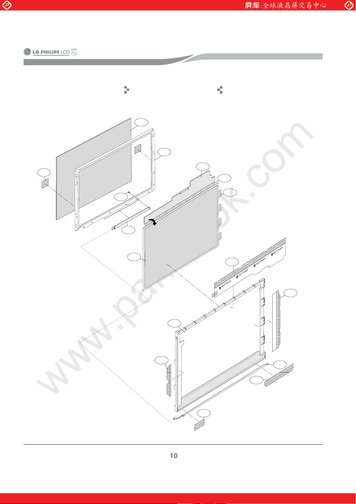
03
01
07
05
08
09
06
04
10
15
16
02
12
13
11
14
www.panelook.com
3. Exploded View
One step solution for LCD / PDP / OLED panel application: Datasheet, inventory and accessory!
www.panelook.com
Page 11
Global LCD Panel Exchange Center
www.panelook.com
4. Exploded View Parts List
No.
1 5135L-0011V Protect Film
2 7250L-0023A Masking, Tape
3 3111L-0149A Case Ass’y
4
5 6091L-0350A BACKLIGHT Ass’y
6 6913L-0260C Lamp Ass’y
7 7250L-0080D Tape, Adhesive
8 7250L-0077A Tape, Teraoka
9 7250L-0074C Tape, Teraoka
10 3550S-0271A Cover shield , Gate
11 3550S-0263A Cover shield , Source
PART NO.
6308L-0039A POLARIZER(TOP)
6308L-00657A POLARIZER(BOTTOM)
English
DESCRIPTION
Korean
12 0IOKL-0039A TCP (D-IC, Gate)
13 0IHYL-0105A TCP (D-IC, Source)
14 6871L-0785A PWB(PCB) Ass’y , Source
15 6632L-0263A INVERTER
16 1STZL-0002B Screw
One step solution for LCD / PDP / OLED panel application: Datasheet, inventory and accessory!
www.panelook.com
Page 12
Global LCD Panel Exchange Center
www.panelook.com
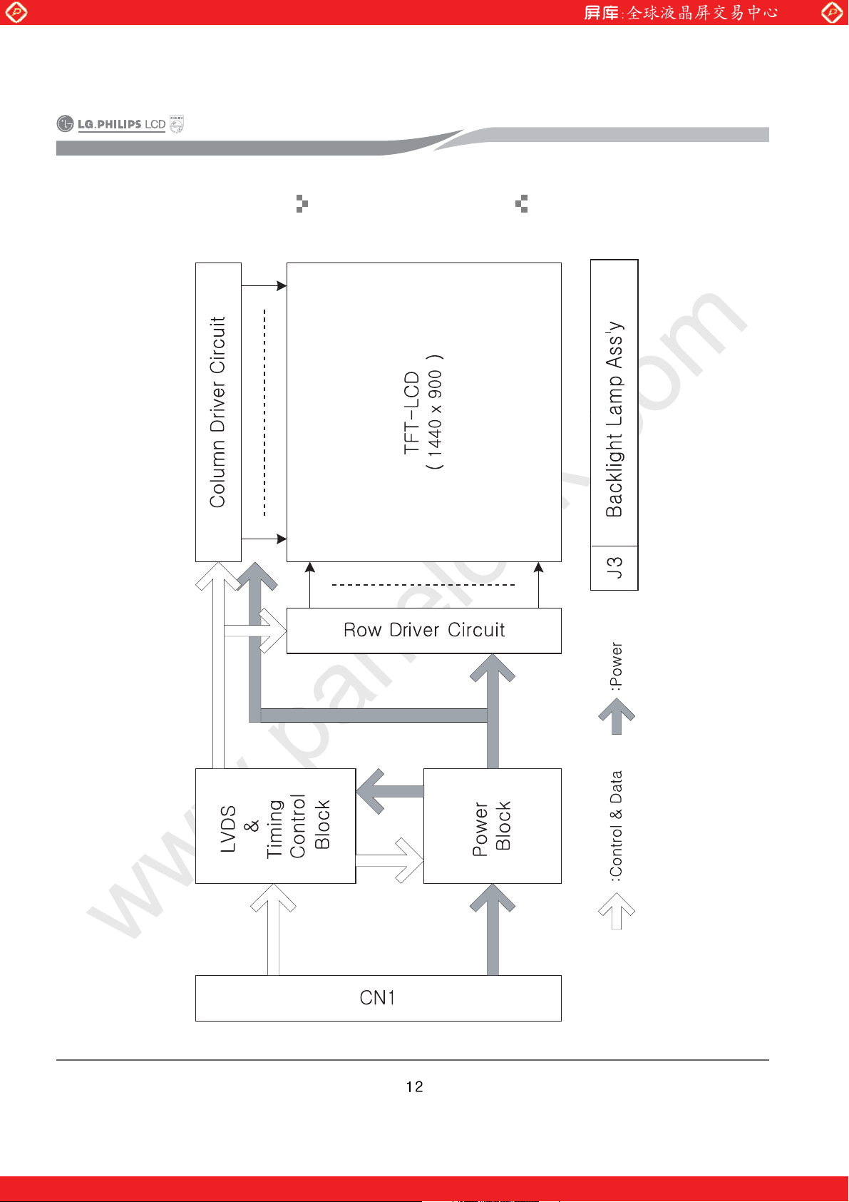
5. Block Diagram
One step solution for LCD / PDP / OLED panel application: Datasheet, inventory and accessory!
www.panelook.com
Page 13

Global LCD Panel Exchange Center
www.panelook.com
No Display
F1 Pool soldering /
Damage check
NO
F1 Replace /
Resoldering
6. Trouble shooting
Means that the screen is not affected by the signal data when you connect the product to Backlight or
user connector and then 3.3V(Vcc) input power ON/OFF.
less than more than
Electricity Consumption
100mA
Damage
CN1 PIN Damage /
Pool soldering check
YES
L1 Pool soldering /
voltage check
YES
NO
NO
Replace /
Resoldering
Replace /
Resoldering
English
Korean
US1 Pool soldering/Short/
Oneself badness check/
RESET check
YES
Source, Gate input/output check
D/IC oneself badness /
Bonding badness
* Notes : It can use a Power IC(US1), One Chip.
NO
NO
Replace /
Resoldering
Replace
One step solution for LCD / PDP / OLED panel application: Datasheet, inventory and accessory!
www.panelook.com
Page 14

Global LCD Panel Exchange Center
www.panelook.com
Abnormal Display
Means that the screen is affected
by the signal data when you
connect the product to Backlight or
user connector and then turn
3.3V(Vcc) input power ON/OFF.
CN1 PIN bend / Pool soldering check
YES
Panel Edge damage check Panel dump
YES
UC1 Input/Output, Voltage, Signal check
Short / Pool soldering /
RESET, RESET2 Voltage check
R17,R18,C11,C12
Around circuit check
VDD,VCC
Around circuit check
VGH Voltage check
D3
Around circuit check
Around circuit check
YES
YES
Voltage check
YES
US1
NO
NO
NO
NO
NO
NO
Replace/Resoldering
Replace/Resoldering
Replace/Resoldering
Replace/Resoldering
Replace/Resoldering
YES
VGL Voltage check
R62, R64
VR1,C41
GMA Voltage check SOURCE DRIVE IC GMA
Internal Short / Open check
Around circuit check
YES
VCOM Voltage check
Around circuit check
YES
Check of lower GMA TP
YES
S - #1, G - #1
Bonding check
YES
Source PCB
NO
NO
NO
NO
NO
Replace/Resoldering
Replace/Resoldering
Replace/Resoldering
Replace
Replace
One step solution for LCD / PDP / OLED panel application: Datasheet, inventory and accessory!
www.panelook.com
Page 15

Global LCD Panel Exchange Center
www.panelook.com
English
Korean
signal and Clock are not divided.
Replace /
Resoldering
NO
Means that the abnormal screen displays at specified color when you connect the product to Backlight
or user connector and then turn 3.3V(Vcc) input power ON/OFF.
YES
CN1 #1~24, AR1,AR2
Pool soldering / Short check
Replace /
Resoldering
NO
#53~64
Short check
UC1 #36~48
Pool soldering /
YES
Replace /
Resoldering
NO
YES
check
R19~R30
Pool soldering / Short Damage
Replace /
Resoldering
NO
YES
Source D/IC
Check input / output
* Notes : Applied with mini LVDS T-con : RGB
Replace /
Resoldering
NO
Source PCB
Internal Short / Open check
Abnormal Color
One step solution for LCD / PDP / OLED panel application: Datasheet, inventory and accessory!
www.panelook.com
Page 16

Global LCD Panel Exchange Center
EDID Operation Screen
www.panelook.com
How to use Button
(1) < Write Data > : Write EDID Data(Standard Data at the left> on EEPROM.
(2) < Write Data&Verify > : After confirming EDID Data, mark the OK, NG.
(3) < Read Data > : Read and mark EDID Data to the EEPROM.
(4) < Read Data&Verify > : Altering marking EDID Data by EEPROM, compare with standard data to mark
OK, NG.
(5) < Init > : Initializing board => OK : GREEN, NG : RED
When board displays RED, After click the inspection option <MENU>, check the address.
(6) < Start > : After connecting the Module, confirm connected state => OK : GREEN, NG : RED
When board displays RED contact connector or confirm power(3.3V).
(7) < Close > : End the program.
How to work
(1) Operate the program.
(2) Click the <lnit> button.
(3) Open the wanted model data, If not, program is edited.
(4) After connecting Module, confirm power(3.3V).
(5) Progress the wanted one(Write & Read).
One step solution for LCD / PDP / OLED panel application: Datasheet, inventory and accessory!
www.panelook.com
Page 17

Global LCD Panel Exchange Center
www.panelook.com
EDID Badness
On the test - screen, when comparing,
standard data with Read data, If it is
failed, it is displayed NG on the testscreen.
CN1 PIN bend / Pool soldering
Damage check
YES
R12, 13, C13
Pool soldering / Damage check
YES
U1Pool soldering / Short /
Oneself badness check
YES
EDID Checksum check
(41)
NO
NO
NO
NO
Replace /
Resoldering
English
Replace /
Resoldering
Korean
Replace /
Resoldering
EDID Re-write
One step solution for LCD / PDP / OLED panel application: Datasheet, inventory and accessory!
www.panelook.com
Page 18

Global LCD Panel Exchange Center
www.panelook.com
7. Timing Check Sheet
Condition : (VCC = 3.3V)
DATA
_ Setup
SSC
_ High
DATA_S = 2.9ns
DATA
_ Hold
DATA_H = 3.5ns
SSC
_ Low
SSC_H = 6.3ns
SSC_L = 5.9ns
One step solution for LCD / PDP / OLED panel application: Datasheet, inventory and accessory!
www.panelook.com
Page 19

Global LCD Panel Exchange Center
www.panelook.com
English
8. Disassembly
Separate Cover
Shield(Gate)
Remove dust on the lower
Polarizer.
Attach dummy sheet on the
lower Polarizer.
Separate Cover
Shield(Source)
Separate Board Ass’y from
Adhesive Tape
Backlight Ass’y.
Take charge of Board
Ass’y in tray.
Separate
Separate
Adhesive/Fixed Tape.
Attach dummy sheet on the
upper Polarizer.
Attach the dummy sheet on
Backlight Ass’y.
Separate Inverter
Fixed Screw.
Remove dust on
the upper Polarizer.
Separate the Cover Shield(Gate).
Should be put on (electro static) wrist strap.
Should be cleared the bottom.
Light the Ion Blower.
Separate the Cover Shield(Source).
Separate
Inverter
Separate
Case Ass’y
Charge the Backlight Ass’y in Bag.
Korean
Separate the Adhesive Tape of the opposite Gate.
One step solution for LCD / PDP / OLED panel application: Datasheet, inventory and accessory!
www.panelook.com
Page 20

Global LCD Panel Exchange Center
www.panelook.com
Separate Cover
Shield(Gate)
Remove dust on the lower
Polarizer.
Attach dummy sheet on the
lower Polarizer.
Separate Cover
Shield(Source)
Separate Board Ass’y from
Backlight Ass’y.
Adhesive Tape
Take charge of Board
Ass’y in tray.
Separate
Separate
Adhesive/Fixed Tape.
Attach dummy sheet on the
upper Polarizer.
Attach the dummy sheet on
Backlight Ass’y.
Separate the
Adhesive Tape &
Backlight Wire
fixed Tape
of the opposite Source PCB.
Separate the fixed screw of Inverter.
Separate Inverter
Fixed Screw.
Remove dust on
the upper Polarizer.
Charge the Backlight Ass’y in Bag.
Separate
Inverter
Separate
Case Ass’y
Separate the Inverter.
If you need to replace the Inverter, separate the
Inverter.
It
s unnecessary to repair the normal TCP / Polarizer.
Separate the Case Ass’y.
One step solution for LCD / PDP / OLED panel application: Datasheet, inventory and accessory!
www.panelook.com
Page 21

Global LCD Panel Exchange Center
www.panelook.com
Separate Cover
Shield(Gate)
Remove dust on the lower
Polarizer.
Attach dummy sheet on the
lower Polarizer.
Separate Cover
Shield(Source)
Separate Board Ass’y from
Adhesive Tape
Backlight Ass’y.
Take charge of Board
Ass’y in tray.
Separate
Separate
Adhesive/Fixed Tape.
Attach dummy sheet on the
upper Polarizer.
Attach the dummy sheet on
Backlight Ass’y.
Separate Inverter
Fixed Screw.
Remove dust on
the upper Polarizer.
Charge the Backlight Ass’y in Bag.
Remove dust on the upper Polarizer.
Attach the dummy sheet on the upper Polarizer.
Separate
Inverter
Separate
Case Ass’y
English
Korean
Separate the Board Ass’y from Backlight Ass’y.
Remove dust on the lower Polarizer.
One step solution for LCD / PDP / OLED panel application: Datasheet, inventory and accessory!
www.panelook.com
Page 22

Global LCD Panel Exchange Center
www.panelook.com
Separate Cover
Shield(Gate)
Remove dust on the lower
Polarizer.
Attach dummy sheet on the
lower Polarizer.
Separate Cover
Shield(Source)
Separate Board Ass’y from
Adhesive Tape
Backlight Ass’y.
Take charge of Board
Ass’y in tray.
Separate
Separate
Adhesive/Fixed Tape.
Attach dummy sheet on the
upper Polarizer.
Attach the dummy sheet on
Backlight Ass’y.
Separate Inverter
Fixed Screw.
Remove dust on
the upper Polarizer.
Charge the Backlight Ass’y in Bag.
Attach the dummy sheet on the lower Polarizer.
Take charge of the Board Ass’y in tray.
Separate
Inverter
Separate
Case Ass’y
Attach the dummy sheet on Backlight Ass’y.
Take charge of the Backlight Ass’y in Bag.
One step solution for LCD / PDP / OLED panel application: Datasheet, inventory and accessory!
www.panelook.com
Page 23

Global LCD Panel Exchange Center
www.panelook.com
English
Detach the protection
film on the lower Polarizer.
Attach
Inverter
Assemble the fixed screw
of Inverter.
Wrap module
Attach dummy sheet on
the upper Polarizer.
Final
inspection
Clean the lower
Polarizer.
Attach a
Adhesive fixed Tape.
Attach the protection film on
9. Assembly
Remove dust the
lower Polarizer.
Assemble the
Case Ass’y.
the upper Polarizer.
Detach the dummy
sheet on Backlight Ass’y.
First screen
inspection
Attach a Cover
Shield(Source)
Detach the protection film
on the upper Polarizer.
Clean the upper
Polarizer.
Attach a Cover
Shield(Gate)
Separate dummy sheet on the
Detach the protection film on the lower Polarizer.
Assemble Board Ass’y
with Backlight Ass’y.
Attach Source PCB/
Gate COF
Attach
Adhesive Tape
upper Polarizer.
Korean
Detach it to opposite direction for preventing
static electricity.
Should be put on (electro static) wrist strap.
Should be cleared the bottom.
Light the Ion Blower.
Polish the lower Polarizer with soft wiper.
One step solution for LCD / PDP / OLED panel application: Datasheet, inventory and accessory!
www.panelook.com
Page 24

Global LCD Panel Exchange Center
www.panelook.com
Detach the protection
film on the lower Polarizer.
Attach
Inverter
Assemble the fixed screw
of Inverter.
Wrap module
Attach dummy sheet on
the upper Polarizer.
Final
inspection
Clean the lower
Polarizer.
Attach a
Adhesive fixed Tape.
Attach the protection film on
Assemble the
Case Ass’y.
the upper Polarizer.
Remove dust the
lower Polarizer.
First screen
inspection
Attach a Cover
Shield(Source)
Detach the dummy
sheet on Backlight Ass’y.
Detach the protection film
on the upper Polarizer.
Attach a Cover
Shield(Gate)
Clean the upper
Polarizer.
Remove dust of lower Polarizer with a Air Gun.
Assemble Board Ass’y
with Backlight Ass’y.
Attach Source PCB/
Gate COF
Attach
Adhesive Tape
Separate dummy sheet on the
upper Polarizer.
Detach the dummy sheet on Backlight Ass’y.
Assemble the Board Ass’y with Backlight Ass’y.
One step solution for LCD / PDP / OLED panel application: Datasheet, inventory and accessory!
www.panelook.com
Page 25

Global LCD Panel Exchange Center
www.panelook.com
Detach the protection
film on the lower Polarizer.
Attach
Inverter
Assemble the fixed screw
of Inverter.
Wrap module
Attach dummy sheet on
the upper Polarizer.
Final
inspection
Clean the lower
Polarizer.
Attach a
Adhesive fixed Tape.
Attach the protection film on
Assemble the
Case Ass’y.
the upper Polarizer.
Remove dust the
lower Polarizer.
First screen
inspection
Attach a Cover
Shield(Source)
Detach the dummy
sheet on Backlight Ass’y.
Detach the protection film
on the upper Polarizer.
Attach a Cover
Shield(Gate)
Clean the upper
Polarizer.
Attach and fold up Source PCB / Gate COF into
Backlight Ass’y bottom.
Be careful TCP(Tape Carrier Package),
COF(Chip On Film)crack.
Detach the protection film on the upper Polarizer.
Assemble Board Ass’y
with Backlight Ass’y.
Attach Source PCB/
Gate COF
Attach
Adhesive Tape
Separate dummy sheet on the
upper Polarizer.
English
Korean
Take a first screen inspection the Backlight.
Check the Backlight dust.
Assemble the Case Ass’y.
One step solution for LCD / PDP / OLED panel application: Datasheet, inventory and accessory!
www.panelook.com
Page 26

Global LCD Panel Exchange Center
www.panelook.com
Detach the protection
film on the lower Polarizer.
Attach
Inverter
Assemble the fixed screw
of Inverter.
Wrap module
Attach dummy sheet on
the upper Polarizer.
Final
inspection
Clean the lower
Polarizer.
Attach a
Adhesive fixed Tape.
Attach the protection film on
Assemble the
Case Ass’y.
the upper Polarizer.
Remove dust the
lower Polarizer.
First screen
inspection
Attach a Cover
Shield(Source)
Detach the dummy
sheet on Backlight Ass’y.
Detach the protection film
on the upper Polarizer.
Attach a Cover
Shield(Gate)
Clean the upper
Polarizer.
Attach the dummy sheet on the upper Polarizer.
Attach the Inverter.
Assemble Board Ass’y
with Backlight Ass’y.
Attach Source PCB/
Gate COF
Attach
Adhesive Tape
Separate dummy sheet on the
upper Polarizer.
If you need to replace the Inverter, separate the
Inverter. It’s unnecessary to repair the normal TCP /
Polarizer.
Assemble the fixed screw of Inverter.
Attach the
Adhesive Tape &
Backlight Wire
fixed Tape
of the opposite Source PCB.
One step solution for LCD / PDP / OLED panel application: Datasheet, inventory and accessory!
www.panelook.com
Page 27

Global LCD Panel Exchange Center
www.panelook.com
Detach the protection
film on the lower Polarizer.
Attach
Inverter
Assemble the fixed screw
of Inverter.
Wrap module
Attach dummy sheet on
the upper Polarizer.
Final
inspection
Clean the lower
Polarizer.
Attach a
Adhesive fixed Tape.
Attach the protection film on
Assemble the
Case Ass’y.
the upper Polarizer.
Remove dust the
lower Polarizer.
First screen
inspection
Attach a Cover
Shield(Source)
sheet on Backlight Ass’y.
Clean the upper
Polarizer.
Attach the Cover Shield(Source).
Attach the Cover Shield(Gate).
Detach the dummy
Detach the protection film
on the upper Polarizer.
Attach a Cover
Shield(Gate)
Assemble Board Ass’y
with Backlight Ass’y.
Attach Source PCB/
Gate COF
Attach
Adhesive Tape
Separate dummy sheet on the
upper Polarizer.
English
Korean
Attach the Adhesive Tape of the opposite Gate.
Separate the dummy sheet on the upper Polarizer.
Detach it to opposite direction for preventing
static electricity.
One step solution for LCD / PDP / OLED panel application: Datasheet, inventory and accessory!
www.panelook.com
Page 28

Global LCD Panel Exchange Center
www.panelook.com
Detach the protection
film on the lower Polarizer.
Attach
Inverter
Assemble the fixed screw
of Inverter.
Wrap module
Attach dummy sheet on
the upper Polarizer.
Final
inspection
Clean the lower
Polarizer.
Attach a
Adhesive fixed Tape.
Attach the protection film on
Assemble the
Case Ass’y.
the upper Polarizer.
Remove dust the
lower Polarizer.
First screen
inspection
Attach a Cover
Shield(Source)
Detach the dummy
sheet on Backlight Ass’y.
Detach the protection film
on the upper Polarizer.
Attach a Cover
Shield(Gate)
Clean the upper
Polarizer.
Polish the upper Polarizer with soft wiper.
Attach the protection film on the upper Polarizer.
Assemble Board Ass’y
with Backlight Ass’y.
Attach Source PCB/
Gate COF
Attach
Adhesive Tape
Separate dummy sheet on the
upper Polarizer.
Take a final inspection.
Wrap the module up in Shielding Bag.
One step solution for LCD / PDP / OLED panel application: Datasheet, inventory and accessory!
www.panelook.com
Page 29

Global LCD Panel Exchange Center
www.panelook.com
10. Parts List
* Specified parts list is subject to change.
PART No. DESCRIPTION SPECIFICATION LOCA. No.
6871L-0785A PWB(PCB) ASSY Source, LP141WP1-TLA1-C11, SURFACE MOUNTING
CIRCUIT_CAPACITOR
0CHZL-0018A CAPACITOR, 47N F, 25 Volt, M PER, X7R(JB), 3216 R/TP AC10
0CH2472K562 CAPACITOR,CHIP[CERAMIC 4.7NF 50V K X 1608 R/TP C1
0CH2104K562 CAPACITOR,CHIP[CERAMIC 0.1UF 50V K X7R 1608 R/TP C10,C104,C105,C106,C11,C114,C115,C116,
C12,C13,C14,C15,C16,C26,C35,C45,C5,C7
0CH2A-0023A CAPACITOR, 0.1U F, 25 Volt, K PER, X7R(JB), 1608 R/TP, T=0.9(MAX) C22
0CH2A-0006A CAPACITOR, 4.7U F, 16 Volt, K PER, X5R(JB), 3216 R/TP, T=1.0(MAX) C25,C3,C34,C36,C37,C38,C4,C41,C47,C50
0CH2A-0011A CAPACITOR, 10U F, 16 Volt, K PER, X5R(JB), 3216 R/TP, T=0.95(MAX) C27
0CH2A-0015A CAPACITOR, 1U F, 25 Volt, K PER, X5R(JB), 1608 R/TP, T=0.9(MAX) C28
0CH2104H942 CAPACITOR,CHIP[CERAMIC 0.1UF 25V Z F 1608 R/TP C30,C51,C54
0CH5681K412 CAPACITOR,CHIP[CERAMIC 680PF 50V J NP0 1608 R/TP C31
0CH2223H562 CAPACITOR,CHIP[CERAMIC 22NF 25V K X 1608 R/TP C52,C53
0CH2103K942 CAPACITOR,CHIP[CERAMIC 10NF 50V Z F 1608 R/TP C6,C8,C9
CIRCUIT_CONNECTOR
6630L-0167B CONNECTOR MDF76LBRW-30S-1H, HIROSE, 30 Pin, 1.0 mm CN1
CIRCUIT_DIODE
0DHZL-0004A DIODE Schottky, BAT750-7-F(0.75A), DIODES, R/TP, SOT-23 D1
0DHZL-0008A DIODE Switching, BAV99-7-F, DIODES, R/TP, SOT-23 D2,D3,D4
English
Korean
CIRCUIT_IC
0IDAL-0010A IC DTML012, 0IDAL-0010A, 100 Pin, TQFP, Tray, LVDS UC1
0ICS240200E IC,CATALYST
0IMXL-0004A IC,MAXIM MAX8758ETG+T, 24 Pin, QFN-24, R/TP, PWM,OP-AMP US1
CAT24WC02Y(CAT24FC02Y), 8 Pin, TSSOP, R/TP, EEPROM
U1
CIRCUIT_RESISTOR
0RHZL10005A RESISTOR,CHIP 100OHM 5% 1/16W 3216 R/TP AR1,AR2
0RH0000C622 RESISTOR,CHIP 0 OHM 1/16W 1608 5% D R/TP R11,R3,R8,R101,R103,R105,R31,
R4,R44,R46,R5,R50,R6,R62,R64
0RH4701C422 RESISTOR,CHIP 4.7K OHM 1/16W 1608 1% D R/TP R12,R13
0RH2202C422 RESISTOR,CHIP 22K OHM 1/16W 1608 1% D R/TP R14
0RH1002C422 RESISTOR,CHIP 10K OHM 1/16W 1608 1% D R/TP R15,R16,R52,R61
0RH3303C422 RESISTOR,CHIP 330K OHM 1/16W 1608 1% D R/TP R17
0RH3903C422 RESISTOR,CHIP 390K OHM 1/16W 1608 1% D R/TP R18
0RH1000C422 RESISTOR,CHIP 100 OHM 1/16W 1608 1% D R/TP R22,R23,R24,R25,R26,R27,R28,R29,R30,
R93,R19,R20,R21
0RH5603C422 RESISTOR,CHIP 560K OHM 1/16W 1608 1% D R/TP R40,R48
0RH2701C422 RESISTOR,CHIP 2.7K OHM 1/16W 1608 1% D R/TP R42
0RH1003C422 RESISTOR,CHIP 100K OHM 1/16W 1608 1% D R/TP R43,R60
0RH1803C422 RESISTOR,CHIP 180K OHM 1/16W 1608 1% D R/TP R49
0RH5602C422 RESISTOR,CHIP 56K OHM 1/16W 1608 1% D R/TP R51
0RH7501C422 RESISTOR,CHIP 7.5K OHM 1 / 16 W 1608 1% D R/TP R53
One step solution for LCD / PDP / OLED panel application: Datasheet, inventory and accessory!
www.panelook.com
Page 30

Global LCD Panel Exchange Center
PART No. DESCRIPTION SPECIFICATION LOCA. No.
0RH3901C422 RESISTOR,CHIP 3.9K OHM 1/16W 1608 1% D R/TP R54
0RH1001C422 RESISTOR,CHIP 1K OHM 1/16W 1608 1% D R/TP R58
0RH0562C422 RESISTOR,CHIP 56 OHM 1/16W 1608 1% D R/TP R63
0RH2201C422 RESISTOR,CHIP 2.2K OHM 1/16W 1608 1% D R/TP R65
0RH3300C422 RESISTOR,CHIP 330 OHM 1/16W 1608 1% D R/TP R70
0RH3002C422 RESISTOR,CHIP 30K OHM 1/16W 1608 1% D R/TP R71
0RH2401C422 RESISTOR,CHIP 2.4K OHM 1/16W 1608 1% D R/TP R74
0RH8201C422 RESISTOR,CHIP 8.2K OHM 1/16W 1608 1% D R/TP R75
0RH1202C422 RESISTOR,CHIP 12K OHM 1/16W 1608 1% D R/TP R79
0RH1802C422 RESISTOR,CHIP 18K OHM 1/16W 1608 1% D R/TP R80
0RH1602C422 RESISTOR,CHIP 16K OHM 1/16W 1608 1% D R/TP R82,R83
0RH1302C422 RESISTOR,CHIP 13K OHM 1/16W 1608 1% D R/TP R87
0RH5601C422 RESISTOR,CHIP 5.6K OHM 1/16W 1608 1% D R/TP R88,R59
www.panelook.com
CIRCUIT_MISCELLANEOUS
6110L-P102A VOLUME PANASONIC, 1K ohm, EVM3WSX80B13 VR1
0LC6012101A INDUCTOR,CHIP PLN6012T-100MR80 TDK R/TP L1
One step solution for LCD / PDP / OLED panel application: Datasheet, inventory and accessory!
www.panelook.com
Page 31

Global LCD Panel Exchange Center
PART No. ITEM DESCRIPTION
6091L-0350A BACKLIGHT ASSY LP141WX1, TL01-C11, HEESUNG PRECISION, PRISM
6913L-0260C LAMP ASSY LP141WX1-TL01-C11
4930L-0397A HOLDER LAMP(H), SILICON
4930L-0398A HOLDER LAMP(G), SILICON
3022L-0307A DIFFUSER UP, 125TL2, LP141WX1-TL01
3034L-0208A REFLECTOR RP17N(0.22T)
3032L-0236A PRISM UP, M268YK(MRC)
3923L-0454A INNER PACKING LP141WP1-TLA1-C11
6632L-0263A INVERTER YPNL-N021A, LGIT, LP141WP1-TLA1/LP141WX1-TL04
6632L-0266B INVERTER K08I026.01, AMBIT, LP141WP1-TLA1/LP141WX1-TL04
0IOKL-0039A IC,OKI ML9132DVVCZ01L, 300 Pin, C-F, R/TP, GATE, 270/300CH, 2VGL
0IHYL-0105A IC,MAGNACHIP HM10SS639A-C3L, 705/720 Pin, C-B, R/TP, SOURCE
6308L-0658A POLARIZER LNC-TEGH2MP-E1032T, 310.14X195.24X0.13T, Nitto, TOP
6308L-0657A POLARIZER LNB-TEGAPMP-E1031B, 307.1X193.3X0.245T, Nitto, BOTTOM
6308L-0740A POLARIZER LGC-TSTH2LP-141E1034T, 310.14 X 195.24 X 0.135T
3850L-0034A LABEL PALLET YUPO 102X165
3850L-0077A LABEL BOX ART 100X100
3850L-0087A LABEL BOX YUPO 152X102
3850L-0088A LABEL ID YUPO 78X37 (TUV PS)
3850L-0085A LABEL B/L YUPO 62X21
3880L-0013D BAG LDPE 240X370
3920L-0389A PACKING TOP EPS LP141WX1
3920L-0390A PACKING BOTTOM EPS LP141WX1
3921L-0147B PACKING ASSY LP141WX1(DELL)
3930L-0007C PALLET WOOD 1040X900X150
3931L-0196B PALLET ASSY LP141WX1(DELL)
3000L-0016Q ANGLE COVER, DW3 1040X900X100
3000L-0013H ANGLE PACKING DW3 875X1022X831
6884L-0038A ACF CP5420ISL,L=1.5MMX200M, T=20UM,SONY
6884L-0027B ACF DP2252KSL, L=2MM*200M, SONY
6884L-0018B ACF CP9220IS L=1.5X200 T=15UM SONY
3890L-0035T BOX SWR4 420X324X269
3111L-0149A CASE ASSY LP141WX1-TL04/LP141WP1-TLA1
3110T-0138A CASE, TOP SUS304(0.3T), LP141WX1-TL01
3550B-0148A COVER, BOTTOM AL5050 H38(0.3T), LP141WX1
3550S-0263A COVER, SHIELD (S), SR93+TERAOKA 631S
3550S-0271A COVER, SHIELD (G),SR93+TERAOKA631S LP141WX1
6071L-0547A POL ASSY SE1W03-AAA
5135L-0011V PROTECT FILM SKYROL SH92,T=0.1,LP141WX1
1STZL-0002B SCREW T/TS PI2,L3(K0.2)
7250L-0041A TAPE(RAW) OPP 70MMX300M(LG,PHLIPS LCD)
7250L-0023A TAPE(RAW) MASKING 20MMX50M
7250L-0074C TAPE(RAW) TERAOKA(631S)+AL35FR
7250L-0080D TAPE(RAW) ADHESIVE, TERAOKA631S(0.05T)
7250L-0023A TAPE(RAW) MASKING 20MMX50M
7250L-0077A TAPE(RAW) TERAOKA 631S #25, 20MMX50M
7250L-0045L TAPE(RAW) (ADHESIVE) PVC T=0.15
7250L-0045Z TAPE(RAW) ADHESIVE PVC0.15T(LP150X08-A2)
www.panelook.com
BACKLIGHT & INVERTER
English
Korean
DRIVE IC
POLARIZER
LABEL
PACKING & BOX
MISCELLANEOUS
One step solution for LCD / PDP / OLED panel application: Datasheet, inventory and accessory!
www.panelook.com
Page 32

Global LCD Panel Exchange Center
www.panelook.com
11. Records of Revision
No.
A00
Date
2003.11.03
Contents Board
Part Number
Customer P/N
0F1124
Note
MSR
One step solution for LCD / PDP / OLED panel application: Datasheet, inventory and accessory!
www.panelook.com
Page 33

Global LCD Panel Exchange Center
www.panelook.com
Base Model : LP121X04-B2
Derivative description of Model
No.
1
Replace of PROTECT FILM 5135L-0009L 5135L-0012A
Contents
12. Derivative description
Part Number
Before After
English
Korean
Note
One step solution for LCD / PDP / OLED panel application: Datasheet, inventory and accessory!
www.panelook.com
Page 34

Global LCD Panel Exchange Center
MEMO
www.panelook.com
One step solution for LCD / PDP / OLED panel application: Datasheet, inventory and accessory!
www.panelook.com
Page 35

Global LCD Panel Exchange Center
www.panelook.com
One step solution for LCD / PDP / OLED panel application: Datasheet, inventory and accessory!
www.panelook.com
Page 36

Global LCD Panel Exchange Center
www.panelook.com
One step solution for LCD / PDP / OLED panel application: Datasheet, inventory and accessory!
www.panelook.com
Page 37

Global LCD Panel Exchange Center
www.panelook.com
One step solution for LCD / PDP / OLED panel application: Datasheet, inventory and accessory!
www.panelook.com
Page 38

Global LCD Panel Exchange Center
www.panelook.com
One step solution for LCD / PDP / OLED panel application: Datasheet, inventory and accessory!
CE_TOP
CE_BOTTOM
www.panelook.com
Page 39

Global LCD Panel Exchange Center
www.panelook.com
MODEL : LP141WP1 - TLA1
March 2006
Printed in Korea
GPN06SM009M
One step solution for LCD / PDP / OLED panel application: Datasheet, inventory and accessory!
www.panelook.com
 Loading...