

Page 1
Liqu id Crystal Display
Product General Specification
1. General Descriptions
The LM220W1 LCD is a Color Active Matrix Liquid Crystal Display with an integral Cold Cathode Fluorescent Lamp(CCFL) back
light system. The matrix employs a-Si Thin Film Transistor as the active element. It is a transmissive type display operating in
the normally black mode. This TFT-LCD has a 22.0 inch diagonally measured active display area with wide-SXGA
resolution(1024 vertical by 1600 horizontal pixel array). Each pixel is divided into Red, Green and Blue sub-pixels or dots which
are arranged in vertical stripes. Gray scale or the luminance of the sub-pixel color is determined with a 8-bit gray scale signal for
each dot, thus, presenting a palette of more than 16,777,216 colors.
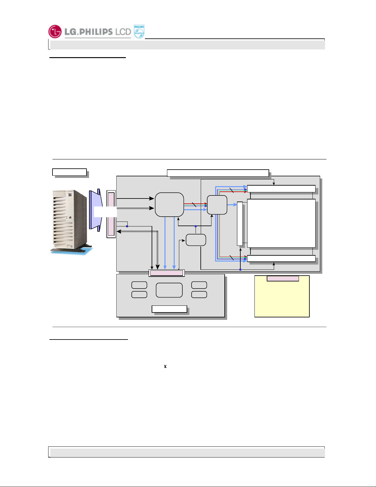
The LM220W1 has been designed to apply the TMDSTM(Transition Minimized differential Signaling) as the
interface method to enables a simple and low -cost implementation in both the host and monitor.
The LM220W1 LCD is intended to support applications where high brightness, wide viewing angle, high color gamut, and high
color depth are very important. In combination with the vertical arrangement of the sub - pixels, the LM220W1 characteristics
provide an excellent flat panel display for office automation products such as monitors.
LM220W1
Host System
Host System
MDR 20PIN
Connector
TX0+/TX0-/SHIELD0
TX1+/TX1-/SHIELD1
TX2+/TX2-/SHIELD2
TXC+/TXC-/SHIELDC
HPD
+5V
DDC
DDC
EDID
PanelLink
SiI151
V
sync H
15PIN Connector
Microcontroller
MNT Logic
MNT Logic
sync
VDD(15V) /
PWR_CTRL
RGB (48bit)
CLK,DTMG
Hsync,Vsync
Power
Block
DPMS
PWR
TFT LCD Module
TFT LCD Module
CTRL
RGB (48bit)
CTRL
Timing
Controller
RGB (48bit)
CTRL
Source Driver Circuit(Up)
SU1 SU7
G1
Gate Driver circuit
Gate Driver circuit
TFT-LCD Panel
(1600 X 1024 pixels)
(1600 X 1024 pixels)
G4
SD1 SD7
Source Driver Circuit(Down)
Source Driver Circuit(Down)
1. GND
2. PWR Ctrl
3. GND
4. PWR (15V)
5. PWR (15V)
6. GND
7. H
sync
8. V
sync
9. GND
10. NC
General Display Characteristics
Followings are general features of the model LM220W1 LCD;
Active display area 22.0 inches(56cm) diagonal
Outsize dimensions 542.0w * 375.0h * 35.3t(typ)mm(Without Inverter)
Pixel pitch 0.294 mm 0.294 mm
Pixel format 1600 horiz. By 1024 vert. pixels
RGB vertical stripe arrangement
Color depth 8-bit, 16,777,216 colors
Display operating mode transmissive mode, normally black
Surface treatments hard coating(3H),
anti-glare treatment of the front polarizer
Interface method TMDSTM interface using SiI151 chips and DFP connector
Lamps Four CCFL(Cold Cathode Fluorescent Lamp)
Source Driver Circuit(Up)
TFT-LCD Panel
15PIN Connector
11. NC
12. +5V(DDC)
13. SDA
14. SCL
15. GND
Ver 1.2 MAY 15 , 2000 Page 1/7
Page 2
Liqu id Crystal Display
Product General Specification
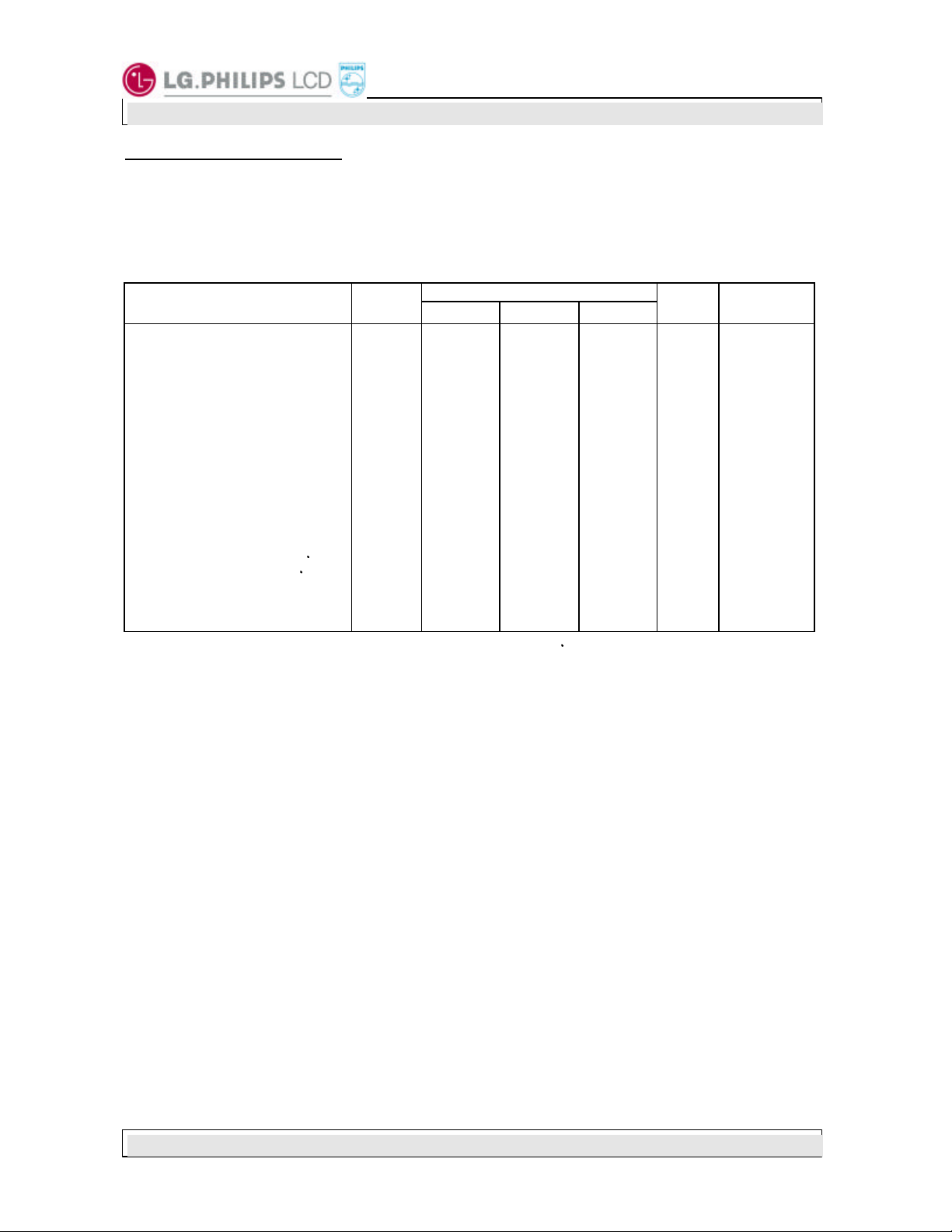
2. Electrical Specifications
2-1. Electrical Characteristics
The LM220W1 requires two power inputs. One input is employed to power the LCD electronics and to
drive the voltages to drive the TFT array and liquid crystal. And the second input which powers the CCFL, is
typically generated by an inverter. The inverter is an external unit to the LCD.
LM220W1
Parameter Symbol
MODULE:
Power Sup ply Input Voltage
Power Supply Input Current
Control Logic Input High
Control Logic Input Low
Control Logic Output High
Control Logic Output Low
LAMP (each CCFL)
Operating voltage
Operating Current
Established Starting Voltage
at 25
at 0
Operating Frequency
Discharge Stabilization time
Life time
Notes: 1. The input current shall be measured at V
frequ ency of 112.2MHz under full white pattern(255gray).
2. The inverter should have symmetrical output voltage and current waveform because the performance
of lamp is extremely influenced by the characteristics of it.
3. The values shall be measured at both end of lamp and are for reference for inverter design.
4. The value shall be measured at the ground cable and does not include loss of external inverter.
5. The lamp frequency shall be designed carefully to evade interference with Hsync frequency.
6. Ts is the time required for the brightness of the center of the lamp to be 95%. Assume the
brightness is 100% after operating 5minutes.
7. The life time is defined as the time at which brightness of lamp is 50% compare to that of initial
value at the typical lamp current on condition of continuous operating at 25 ± 2°C.
Table 1 Electrical Characteristics:
Values
Min. Typ. Max.
V
DD
I
DD
V
IH
V
IL
V
OH
V
OL
V
BL
IBL
F
BL
Ts
14.25
-
2.6
-
2.5
-
1070
3.0
1400
2100
40
-
15000
of 15.0Vdc at 25 , refresh rate of 60Hz, and pixel clock
DD
15.0
0.8
-
-
-
-
860
8.0
-
-
50
-
20000
9.0
16.5
1.0
-
0.8
-
0.5
830
-
-
60
3
-
Units Notes
VDC
A
VDC
VDC
V
RMS
mA
V
RMS
V
RMS
KHz
minutes
hours
1
2
3
4
3
5
6
7
Ver 1.2 MAY 15 , 2000 Page 2/7
Page 3
Pin
Pin
14 15
18 19 20
Product General Specification
LM220W1
Liqu id Crystal Display
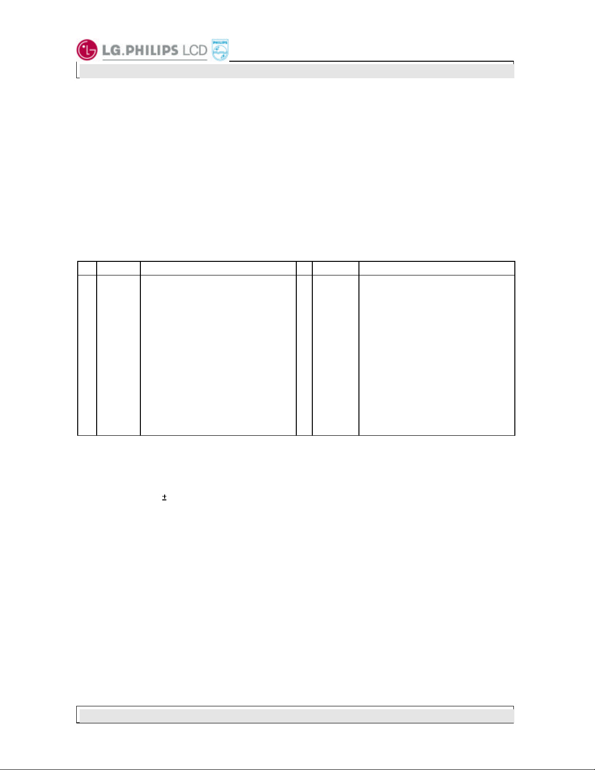
2-2. Interface Connections
Interface chip in host side, must be used TMDSTM, part No. SiI150, designed by Silicon Image Inc., or its
equivalent.
This LCD employs three kinds of interface connections. A 20 pin connector called by DFP connector, is used
for TMDS signals from the host computer. This connector is fully compatible with DFP standard. Please, refer
to Digital Flat Panel(DFP ) standard for the detailed descriptions. A 15-pin connector is used for LCD module
power and LCM controls signal from external monitor control circuits. And four connectors, a two pin connector,
are used for the integral backlight system.
The pin configuration for the 20 pin DFP connector is shown in the table below.
Table 2 DFP CONNECTOR PIN CONFIGURATION (DFP Standard)
Symbol Description
1
TX1+
2
TX1-
3
SHLD1
4
SHLDC
5
TXC+
6
TXC-
7
GND
8
+5V
9
NC
10
Notes: 1. All shield pins and GND(ground) pin should be connected together and should also be connected
The following is a preliminary list of DFP compatible connectors.
Please, contact connector manufacturer for detail description of this connector.
NC
2. This +5V is only for external monitor control circuits and directly connected to 15 pin connector.
3. This pin is internally connected to pin 8 (+5V) in LCM circuits.
4, 5. These pins are only for external monitor control circuits and directly connected to 15 pin
6. Refer to appendix 1 regarding TMDS signal mapping.
1. 3M - Mini Delta Ribbon(MDR) Connector .050” series
2. AMP
3. Molex
TMDS positive differential output
(channel1)
TMDS negative differential output
(channel1)
Shield for TMDS channel 1
Shield for TMDS clock
TMDS positive differential output
(reference clock)
TMDS negative differential output
(reference clock)
Logic Ground
Logic +5V Supply (See note 2)
No Connection
No Connection
to the LCD’s metal frame.
The specifications for this source are the same as those defined in the VESA DDC Standard
V3.0(+5V 5%, 50mA minimum, 1.0A maximum).
connector.
a) Receptacle : P/N 10220-55G3 VC
b) Plug : P/N 10120 -6000 EC
a) Receptacle : P/N 917738 -2
b) Plug : P/N 2-175677-2
a) Receptacle : P/N 52515-2011
b) Plug : P/N 52316 -2011
Symbol Description
11
12
13
16
17
DDC_DAT
DDC_CLK
TX2+
TX2-
SHLD2
SHLD0
TX0+
TX0-
NC
HPD
TMDS positive differential output
(channel2)
TMDS negative differential output
(channel2)
Shield for TMDS channel 2
Shield for TMDS channel 0
TMDS positive differential output
(channel 0)
TMDS negative differential output
(channel 0)
Logic Ground
Hot Plug Detection (See note 3)
DDC2B Data (See note 4)
DDC2B Clock (See note 5)
Ver 1.2 MAY 15 , 2000 Page 3/7
Page 4

Liqu id Crystal Display
Product General Specification
A 15 pin connector for external monitor control circuits, is a model 53261 manufactured by Molex. The mating
connector part number is 51021 or its equivalent. The pin configuration for this connector is shown in the table
below.
Table 3 15 PIN CONNECTOR PIN CONFIGURATION
LM220W1
Pin
1
2
3
4
5
6
7
8
9
10
11
12
13
14
15
Symbol Description Notes
GND
PWR_CTRL
GND
VDD
VDD
GND
H
SYNC
V
SYNC
GND
NC
NC
+5V_DDC
SDA
SCL
GND
Ground
LCM power control input signal
Low : LCM power down except SiI151 receiver
High : Normal operation mode
Ground
LCM power supply, +15V 5%
LCM power supply, +15V 5%
Ground
H
out from SiI151 receiver
SYNC
V
out from SiI151 receiver
SYNC
Ground
No connection (Reserved)
No connection (Reserved)
+5V out for DDC
DDC data line out
DDC clock line out
Ground
1
2
3
Notes: 1. All GND(ground) pins should be connected together and should als o be connected to the LCD’s
metal frame.
2. LCM power control input signal for power saving mode. If this pin is held low state, LCM goes to
power saving mode except SiI151 receiver.
3. Pin 12, 13, 14 are for DDC2B communication between host computer and external monitor control
circuits. These pins are directly connected to 20 pin DFP connector.
The backlight interface connector is a model BHSR-02VS-1, manufactured by JST. The mating connector
part number is SM02B-BHS-1 or equivalent. The pin configuration for the connector is shown in the table
below.
Table 4 BACKLIGHT CONNECTOR PIN CONFIGURATION
Pin Symbol Description Notes
1
2
HV
LV
Lamp power input
Ground
1
2
Notes: 1. The input power terminal is colored pink. Ground pin color is white.
2. The backlight ground should be common with LCD metal frame.
Ver 1.2 MAY 15 , 2000 Page 4/7
Page 5

<Front View>
LM220W1
Liqu id Crystal Display
Product General Specification
Ver 1.2 MAY 15 , 2000 Page 5/7
Page 6

<Rear View>
LM220W1
Liqu id Crystal Display
Product General Specification
Ver 1.2 MAY 15 , 2000 Page 6/7
Page 7

Product General Specification
LM220W1
Liqu id Crystal Display
4.PRECAUTIONS
The LCD Products listed on this documents are not suitable for use of Military,Industry,Medical etc.
system.
If customers intend to use thes e LCD products for above application, Please contact ours sales
people in advance.
Ver 1.2 MAY 15 , 2000 Page 7/7
 Loading...