

LGL Electronics SPIN1 Instruction Manual
MANUALE DI ISTRUZIONE
INSTRUCTION MANUAL
BEDIENUNGSANLEITUNG
MANUAL DE INSTRUCCION
EL K‹TABI
ALIMENTATORE DI FILO A SPIRE SEPARATE
YARN ACCUMULATOR WITH SEPARATE COILS
SCHUSSFADENGEBER MIT GETRENNTEN WINDUNGEN
ALIMENTADOR DE HILO DE ESPIRAL SEPARADOS
‹PL‹K ARASI MESAFEL‹ ‹PL‹K BESLEY‹C‹S‹
VALID FROM SERIAL
n° KPLG 10/0001
取扱説明書
セパレート型コイル式 ヤーンアキュームレータ


N° Doc. : MAN/SPIN 1 Rev. 0
L.G.L. Electronics is flattered by your choice
and thanks you for the preference granted
SPIN 1
Yarn accumulator
INSTRUCTION MANUAL
ISSUED BY: Service Manager
Data: 01/05/14
APPROVED BY:
Technical
Manager
Data: 01/05/14

WARNINGS
4
1) Switch off the power supply box and the yarn accumulator before
starting any part connection, maintenance or replacement.
2) During standard machine operation, the yarn accumulator may
suddenly start up without prior warning.
CAUTION: the orange lights do not signal that the yarn accumulator
is ON, but that the accumulator has gone into an alarm mode.
Therefore, during standard operation they should be OFF.
3) Before yarn accumulator start-up, inspect it physically for
damage (moving parts).
4) Strictly avoid touching any moving part during accumulator
operation
5) Due to the high accuracy and sensitivity of the tension sensor,
mobile or cordless phones might interfere with it. Operation of
the device and the sensor is not affected. In any case, to avoid
interference, we recommend that you keep a minimum distance
of 3 metres.
6) Only use the original L.G.L. Electronics spare parts and
accessories.
7) Any repairs to the accumulator’s electronic parts must be
performed by appropriately qualified personnel, regularly
authorised by L.G.L. Electronics accordingly.
8) Yarn accumulators that are moved from warehouse storage into
a warmer weaving mill environment may develop condensation;
please wait until they are completely dry before connecting them
up. Failure to do so may damage the electronic components.

5
WARNINGS
TIPS TO KEEP THE YARN ACCUMULATOR IN GOOD WORKING ORDER
AND EXTEND ITS SERVICE LIFE.
For you to achieve and maintain a satisfactory performance of the yarn
accumulator over the years, we suggest you should follow some simple steps:
1. Yarn accumulators that are moved from warehouse storage into a warmer
weaving mill environment may develop condensation; please wait until
they are completely dry before connecting them up. Failure to do so may
damage the electronic components.
2. Water and moisture are harmful to the yarn accumulator’s electronics.
Keeping the yarn accumulator operating for long periods of time in very
humid environments (humidity greater than 80%) or using wires
impregnated with water may quickly result in damages to electronic cards.
Moreover, never clean the yarn accumulator with water or similar liquids.
3. Machines working in very dusty environments require greater
maintenance. A clean workplace clean can prevent residual dust or dirt
from negatively affecting machine performance by stressing its moving
parts. The latter are protected, anyway dust accumulation might result in
hindered movement and, hence, early wear.
4. We recommend that you store yarn accumulators that are not used for
long periods of time in the appropriate polystyrene boxes, which
guarantee optimum storage conditions.
5. When the yarn accumulator is being threaded, used the appropriate yarn
taker. Do not use other tools, especially metal ones.


7
INDEX
page
1 GENERAL FEATURES................................................................... 8
1.1 Main parts – Control and adjustment points................................... 8
1.2 Control buttons................................................................................ 9
1.3 Display unit ..................................................................................... 11
1.4 Main menu map............................................................................... 12
1.5 Overall dimensions.......................................................................... 13
1.6 Intended use – Technical and operational features......................... 14
2 INSTALLATION............................................................................... 15
2.1 Yarn accumulator installation .......................................................... 15
2.2 Power supply box ............................................................................ 19
2.3 Module to add INC DEC signal ....................................................... 26
3 START-UP AND THREADING........................................................ 28
3.1 Offset............................................................................................... 28
3.2 Yarn winding/threading .................................................................... 29
3.3 Quick start-up .................................................................................. 31
4 PROGRAMMING THE OPERATING PARAMETERS .................... 32
4.1 Setup menu ..................................................................................... 32
4.2 Parametres...................................................................................... 33
4.3 Device Control via serial communication ........................................ 52
5 DEVICE TURN-OFF........................................................................ 54
5.1 Hardware turn-off ............................................................................ 54
5.2 Software turn-off.............................................................................. 54
6 MESSAGES AND ALARMS........................................................... 55
6.1 Messages ........................................................................................ 55
6.2 Alarms ............................................................................................. 56
7 CONVERSION TABLE.................................................................... 59
8 SCRAPPING................................................................................... 60
SPARE PARTS......................................................................................... 61

8
Main parts:
1 • Tensioner
2 • Separating pin
3 • Separation control screw
4 • Yarn feeding wheel
5 • Alarm lights
6 • Display unit
7 • Load cell
8 • Yarn guide ceramic
9 • Connector
10 • Fixing screw
1.1 MAIN PARTS – CONTROL AND ADJUSTMENT POINTS
1 - GENERAL FEATURES
2
3
5
6
5
9
10
1
4
8
7
9
1 - GENERAL FEATURES
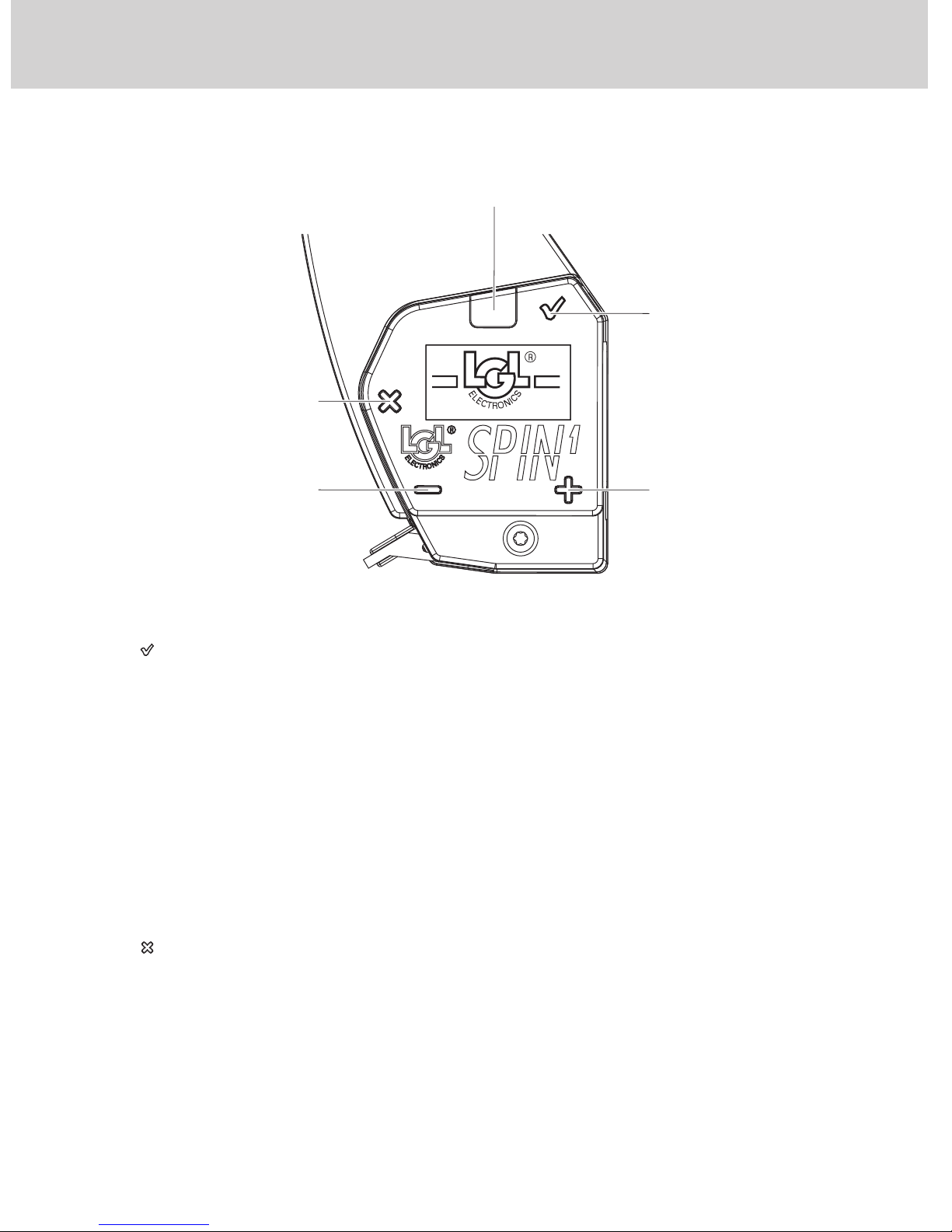
1.2 CONTROL BUTTONS
“ ” Enter button
The Enter button is used to access the reference tension programming
function and the sub-menus and confirm an entry.
The purpose of the button depends on the menu you are in.
Moreover, this button enables you to:
− reinstate the device when it is in the yarn winding (or threading) state
“WAIT:YarnWinding”;
− turn on the device when it stands in the “SPIN OFF state”;
− put the device in the self-resetting yarn winding/threading state
“WAIT:YarnWinding” (see chapter 3.1). Keep this button pressed for about
1 second.
“ ” Escape Button
The Escape button is used to cancel an alarm (if the alarm displayed can be
cancelled), exit submenus and quit a value editing page.
The purpose of this button depends on the menu you are in. Moreover, this
button allows you to:
− reinstate the device when it is in the yarn threading state
“WAIT:YarnWinding”;
− switch off the device by holding this button pressed for about 5 seconds
(complete switch-off “SPIN OFF”);
ALARM LIGHT
"ESC" BUTTON
"-" BUTTON
"+" BUTTON
"ENTER" BUTTON
VER .
00 . 00

10
1 - GENERAL FEATURES
− put the device in the non-self-resetting yarn threading state
“WAIT:YarnWinding” (see chapter 3.1). To this purpose, hold this button
pressed for about 1 second.
“ ” Button
This button is used to scroll menus and submenus upwards. Moreover, it is
used to increase values in data entry/edit sessions.
If it is held pressed while a datum is being edited in the programming mode,
the value will go up quickly.
This button is also used to reinstate the device when it is in the yarn
threading state “WAIT:YarnWinding”.
Tasto “ ”
This button is used to scroll menus and submenus downwards. Moreover, it
is used to decrease values in data entry/edit sessions.
If it is held pressed while a datum is being edited in the programming mode,
the value will go down quickly.
This button is also used to reinstate the device when it is in the yarn
threading state “WAIT:YarnWinding”.
“ ” & “ ” pressed simultaneously
While entering/editing parameters which may have a very large range of
values, the increase/decrease step can be changed by simultaneously
pressing the buttons “+” and “-”.
Note: his function is only enabled in the parameter entry/edit mode.
See figure below:
Increase/decrease step
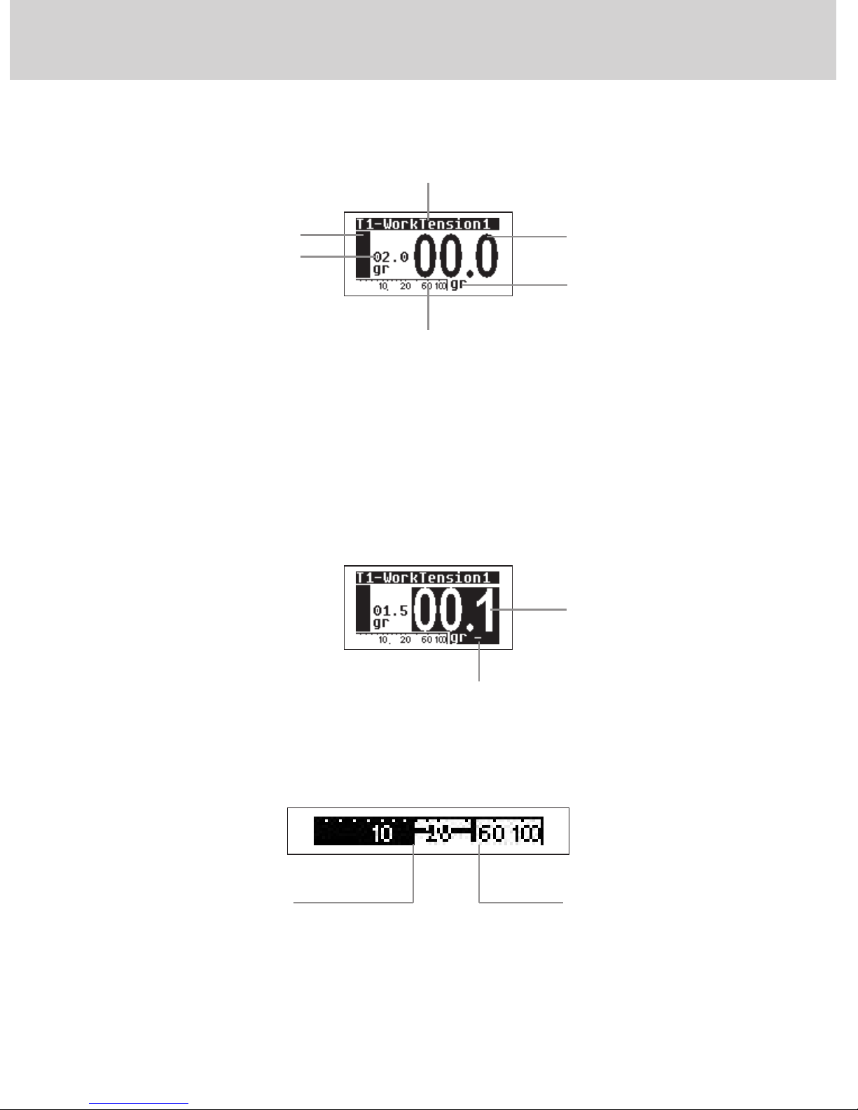
1.3 DISPLAY UNIT
- Negative number display
Negative numbers are displayed with the "-" sign on a black background.
- Tension bar
11
1 - GENERAL FEATURES
Icon bar
Desired tension
Measurement unit
Measured tension
Work tension/ alarms
Tension display bar– this bar shows the average yarn
tension through a segment indicating the peak tension
“-” sign
Negative number
Average tension peak tension
12
1 - GENERAL FEATURES
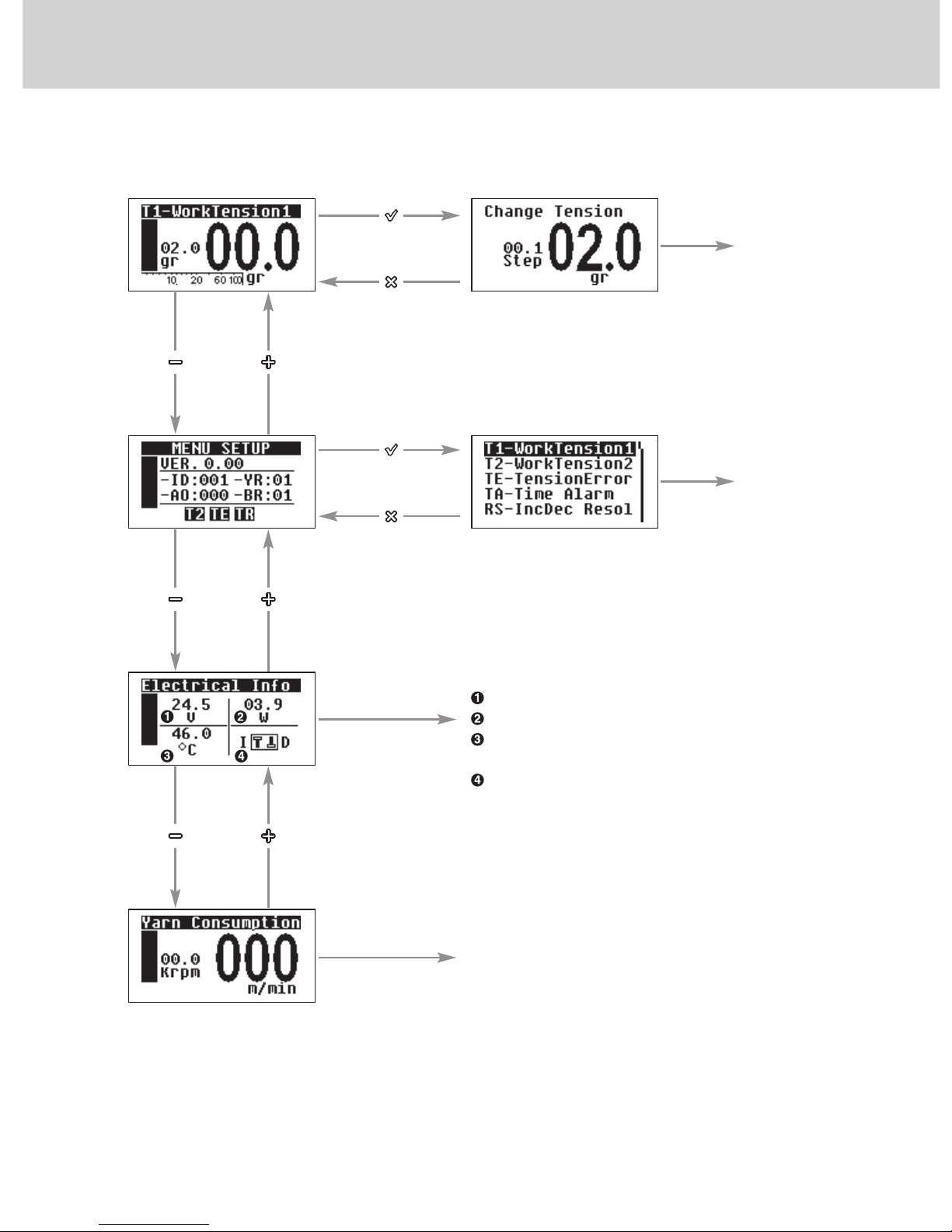
1.4 MAIN MENU MAP
SEE
CHAP. 3.2
SEE
CHAP. 4
Information on:
Feeding voltage (Volt)
Power Consumption (Watt)
Electronic card temperature
(degrees Celsius);
State of signals INC and DEC
(present in version 4.19 - 3.61)
Information on yarn consumption
and wheel speed
13
1 - GENERAL FEATURES
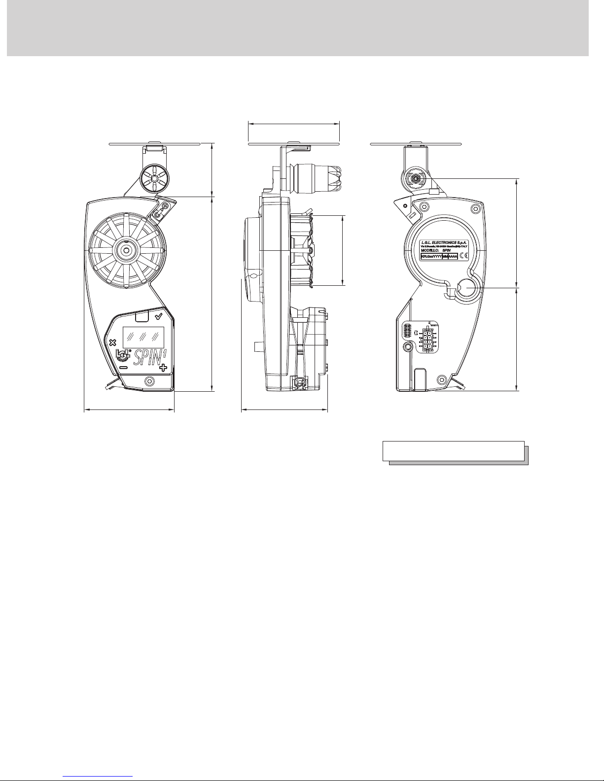
1.5 OVERALL DIMENSIONS
40140
60
ø 65
ø 50
77,5
73,5
50
Weight 350 g

14
1 - GENERAL FEATURES
1.6 INTENDED USE – TECHNICAL AND OPERATIONAL FEATURES
SPIN1 is a yarn accumulator featuring separate coils suitable for all types of
knitting machines or textile machines requiring constant tension yarn feed-in.
Operational Features:
• Quick reaction to machine speed changes without causing tension peaks
on the yarn
• Quick reaction to set tension changes.
• Yarn tension adjustment from 0.5g to 100g.
• Maximum torque available at low speeds, too
• Special concern for reduction of energy consumption
• Yarn absorption measurement
• Easy installation and use
• RS485 and CAN BUS serial communication option
• Connections: via flat cable or traditional cable
• Ceramic tension sensor: guarantees accuracy, precision and quick response
Technical Specifications:
• Power supply voltage data: V = From 24VDC ± 10% to 60VDC ± 10%
(min 21,6 VDC - max 66 VDC)
• Average power in normal operation: 5W-15W (much relying on the type
of work process
• Peak power: 70W
• Automatic speed adjustment up to a maximum value of 1400 m/min.
• Coil separation feature from 0 to 2mm.
• A-weighted sound pressure level, at maximum speed, < than 70dB (A)
• Operation and storage conditions: Room temperature: +10 to +40 °C
• Max. humidity: 80%
15
2 - INSTALLATION
2.1 YARN ACCUMULATOR INSTALLATION
N.B.: Yarn accumulators that are moved from warehouse storage into
a warmer weaving mill environment may develop condensation; please
wait until they are completely dry before connecting them up.
Failure to do so may damage the electronic components.
For installation of the yarn accumulator onto the machine, proceed as follows:
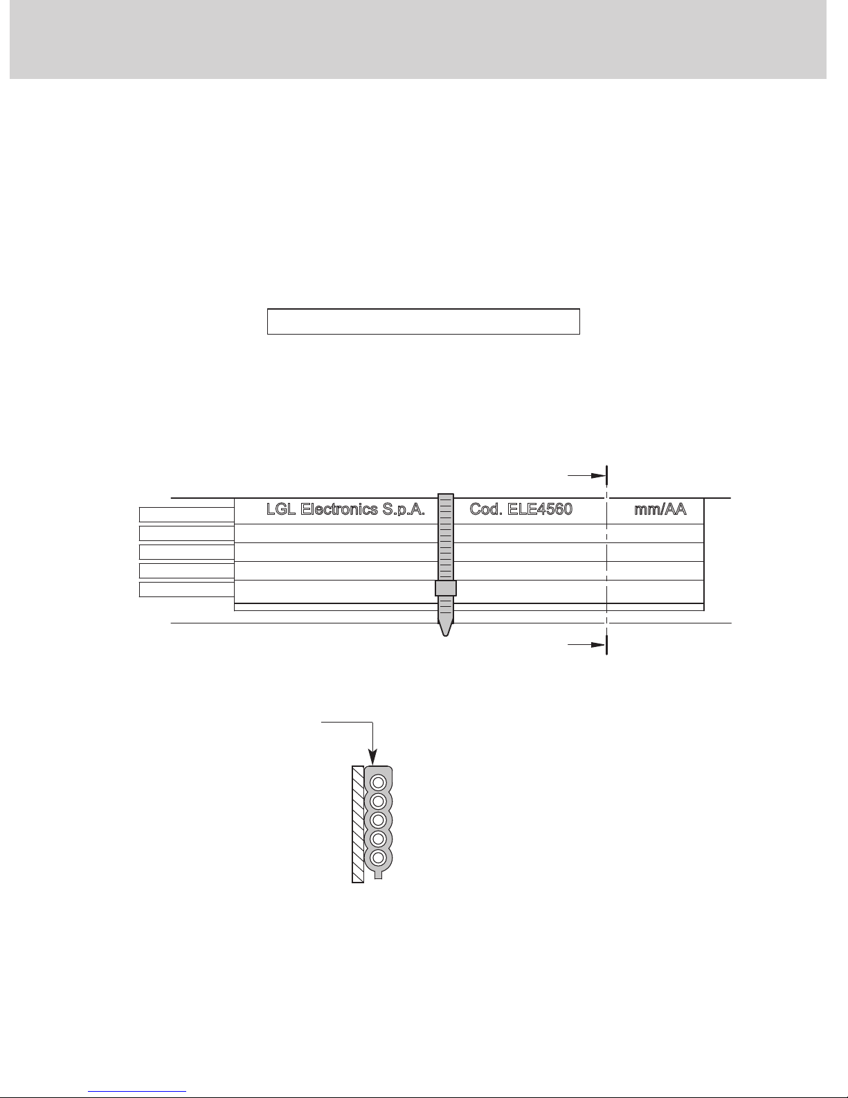
FLAT CABLE VERSION
1. Place the flat cable onto the support ring and fix it by means of straps.
The text “LGL Electronics” on the cable must be on the right reading
side; the flat cable lip shall be turned downwards.
"A"
"A"
5 - CANH / LSA
4 - CANL / LSB
3 - STOP Signal
2 - Positive Power supply
1 - Power supply voltage 0V
Keep flat cable with top
portion facing ring profile.
N.B.: The support ring shall be sized as follows:
- height not less than 25mm
- max. thickness 10 mm
BLUE
BROWN
BLACK
RED
YELLOW/GREEN
SECTION "A-A"
16
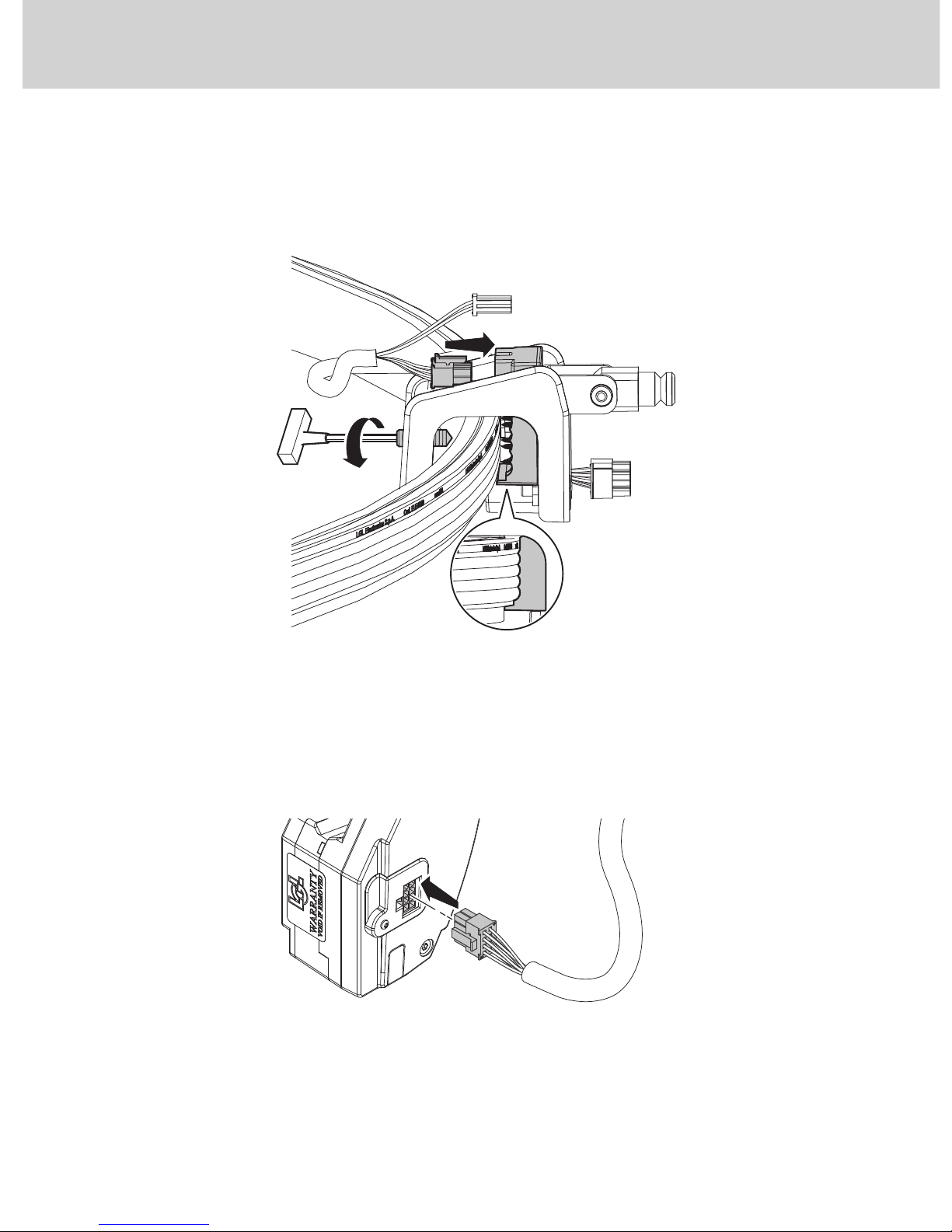
2 - INSTALLATION
2. Connect the cable connector to clamp connector (A).
3. Place the clamp in the desired position; close the clamp grab screw until
the strip is punctured (B), taking care to have the connector profile match
that of the plate (C).
4. Connect the (A1N1SA792-0200) cable connector to the related
connector found on the accumulator and fasten it by tightening on the
accumulator the screw that is in the cable protection housing (D).
A
C
B
DEC
INC
D
17
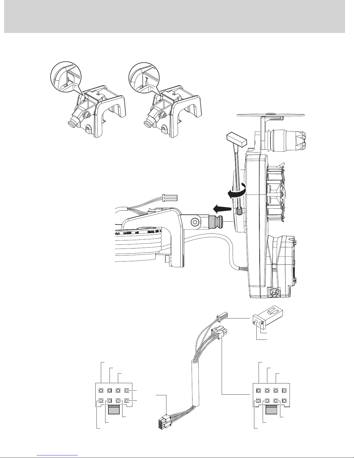
2 - INSTALLATION
5. Fix the accumulator to the clamp pin with the related screw (E).
DEC
INC
CANL / LSB
STOP
+Vdc POWER
CANH / LSH
ID / ADDRESS
GND
1 2 3 4
5678
CANL / LSB
STOP
+Vdc POWER
CANH / LSH
ID / ADDRESS
GND
1 2 3 4
5678
INC
DEC
E
DEC
INC
A1C2SA072-T A1C2SA072
Place the terminated clamp on the first and the last SPIN in the
row. On the others, use the unterminated clamp. Do not use
more than two terminated clamps along the same line, as
communication problems might result.
Unterminated
clamp
Terminated
clamp
18
2 - INSTALLATION
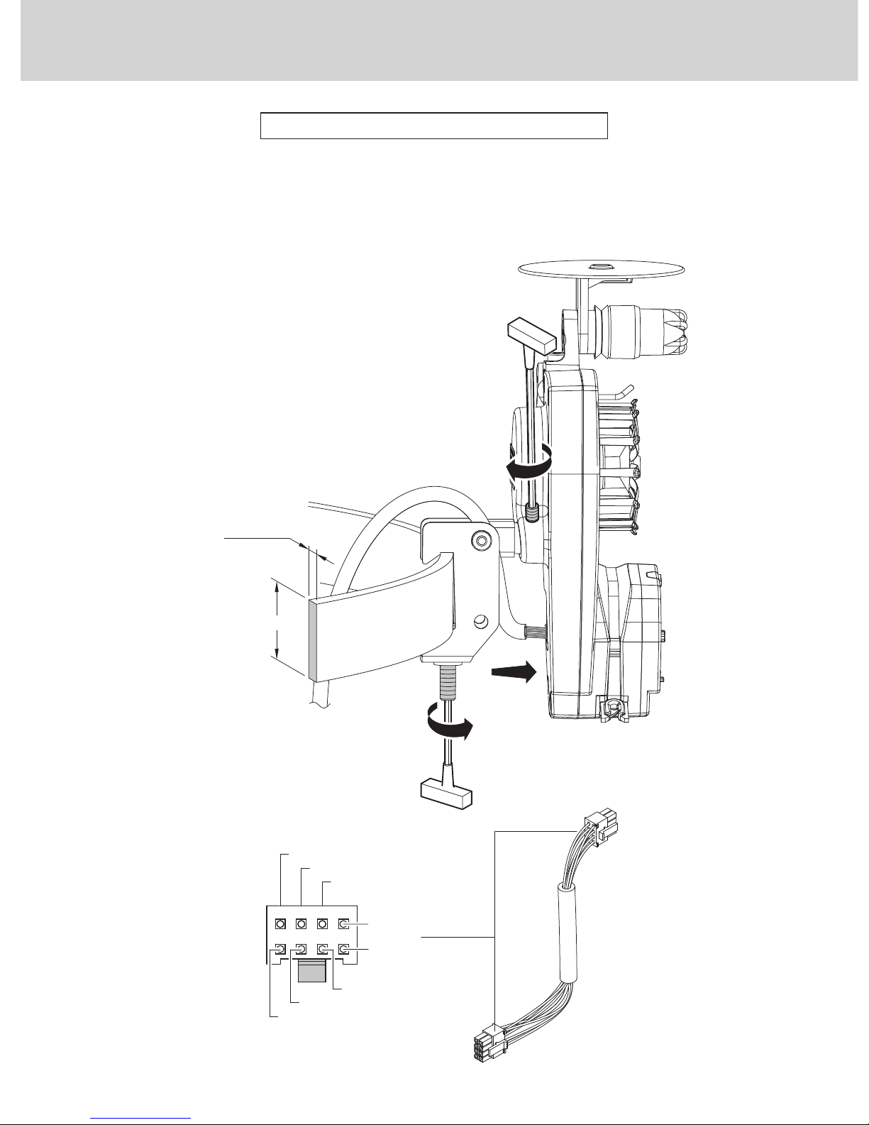
SINGLE-CABLE VERSION
1. Fix the clamp (A1C2SA060) with the related screw in the desired position
on the support ring.
2. Connect the single-cable (A1N1SA791) into the accumulator.
3. Fix the accumulator to the clamp.
N.B.: The support ring shall
be sized as follows:
- height ranging between 15 and 30 mm
- max. thickness 5 mm
max 5 mm
3
1
2
15÷30 mm
CANL / LSB
STOP
+Vdc POWER
CANH / LSH
ID / ADDRESS
GND
1 2 3 4
5678
INC
DEC
 Loading...