

LGL Electronics EcoPower Instruction Manual
ALIMENTATORE DI FILO A SPIRE SEPARATE
YARN FEEDER WITH SEPARATE COILS
DELIVREUR DE FIL A SPIRES SEPAREES
SCHUSSFADENGEBER MIT GETRENNTEN WINDUNGEN
ALIMENTADOR DE HILO DE ESPIRAL SEPARADOS
İPLİK ARASI MESAFELİ İPLİK BESLEYİCİSİ
MANUALE DI ISTRUZIONE
INSTRUCTION MANUAL
NOTICE D'INSTRUCTION
BEDIENUNGSANLEITUNG
MANUAL DE INSTRUCCION
EL KİTABI

TRADUZIONI DELLE ISTRUZIONI ORIGINALI.
TRANSLATION OF THE ORIGINAL INSTRUCTIONS.
TRADUCTIONS DES INSTRUCTIONS D’ORIGINE.
ÜBERSETZUNG DER ORIGINALANLEITUNGEN.
TRADUCCIÓN DE LAS INSTRUCCIONES ORIGINALES.
ORJİNAL TALİMATLARIN TERCÜMESİ.
原始使用说明的翻译.
Scope of supply: Design, manufacture and after sales service of yarn and weft
feeders, measuring winders, stands, creels and oil systems for textile machinery.

Doc. no.: MAN/ECOPOWER Rev. 0
L.G.L. Electronics is gratified by your choice
and thanks you for the preference
yarn feeder
INSTRUCTION MANUAL
ISSUED BY: Service
Manager
Date: 01/07/14
APPROVED BY: Technical
Manager
Date: 01/07/14
WARNINGS
4
1) Power down the yarn feeder’s power supply box mains switch
before beginning any power supply hook-up, maintenance or part
replacement operations.
2) During standard machine operation, the yarn feeder may
suddenly start up without prior warning.
CAUTION: the orange lights do not signal that the yarn feeder
is ON, but that the feeder has gone into an alarm mode.
Therefore, during standard operation they should be OFF.
3) Before yarn feeder start-up, inspect it physically for damage
(check the flywheel/the eyelet/all moving parts).
Wear Personal Protective Equipment (gloves, shoes) during
transportation and installation of the feeders and the power
supply kit, if any, to avoid crushing hazards in the event of a fall.
4) Strictly avoid touching any moving part during feeder operation.
Do not wear clothes and clothing accessories that are likely to
get caught in the moving parts. Gather up long hair.
5) Lubricants may be used to make the yarn slide more easily. The
user must refer to the Material Safety Data Sheet of the
products used. Keep the feeder clean.
6) Only use the original L.G.L. Electronics spare parts and
accessories.
7) Any repairs to the feeder’s electronic parts must be performed
by appropriately qualified personnel, regularly authorised by
L.G.L. Electronics accordingly.
8) Yarn feeders that are moved from warehouse storage into a
warmer knitting mill environment may develop condensation;
please wait until they are completely dry before connecting them
up. Failure to do so may damage the electronic components.
9)
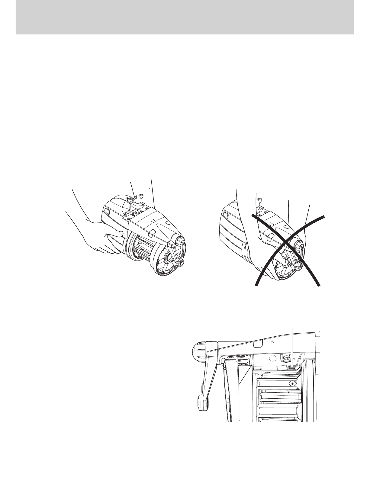
Never pick the yarn feeder up by its yarn spool body or by its
tensioning unit.

5
WARNINGS
ADVICE TO ALWAYS KEEP THE FEEDER IN PERFECT WORKING
ORDER AND EXTEND ITS SERVICE LIFE.
For an always satisfying performance of the weft feeder over the years, we
deem it advisable to provide you with some simple tricks:
1. At the time of installation, passing from the store to the warm knitting
environment, Condensation may form on a yarn feeder that has been
stored in cold places when this is brought into a warm area.Wait until this
is completely dry before connecting it, otherwisethe electronic
components could be damaged.
2. Water and dampness may harm the electronic parts of the feeder.
Operating the weft feeder for long time periods in extremely dump
environments (dampness exceeding 80%) or using water-impregnated
threads might quickly compromise the electronic cards. Moreover, the
feeder shall not be cleaned with water or similar substances.
3. Machines working in environments featuring a lot of dust require
increased maintenance. By prevent the knitting environment clean, you
avoid residual dirt and dust from compromising the performance of the
machine by stressing the moving parts. The latter are protected, but the
accumulation of dust might result in a more difficult movement and, as
consequence, in early wear-and-tear.
4. We suggest storing feeders that are not used for long time periods in the
special polystyrene boxes, which ensure the best storage.
5. When the weft feeder is being loaded, use the special heddle tool. Do not
use other tools, especially if made from metal, as he inlet sensor might
be damaged, along with any outlet brakes.

6
INDEX
page
1 GENERAL FEATURES ............................................................................. 8
1.1 Main parts - Control and adjustment points .............................................. 8
1.2 Overall dimensions .................................................................................... 9
1.3 Intended use – technical and operational features .................................... 10
1.4 Handling and storage instructions ............................................................. 11
1.5 Input feeler ................................................................................................. 11
1.6 Optical output sensor ................................................................................. 12
1.7 Yarn spool body winding reserve control feeler.......................................... 12
1.8 Yarn output detection feeler........................................................................ 13
2 INSTALLATION AND START-UP .............................................................. 14
2.1 Yarn feeder installation and start-up .......................................................... 14
2.2 Power supply box ....................................................................................... 17
2.3 Transformer kit ............................................................................................ 19
2.4 Detection of yarn breakage on feeder outlet: KLS KIT............................... 21
3 THREADING AND ADJUSTMENTS ......................................................... 22
3.1
Threading the yarn feeder with the TWM tension modulator
.......................... 22
3.2 Speed adjustment ...................................................................................... 23
3.3 Tensioning adjustment ............................................................................... 23
4
OPERATIONAL PARAMETERS AND YARN CONSUMPTION KIT
............. 24
4.1 DIP-SWITCH settings ................................................................................. 24
4.2 Yarn consumption kit installation ............................................................... 25
5 MAINTENANCE OPERATIONS................................................................. 27
5.1 Removal of the yarn spool body ................................................................ 27
5.2 Replacement of the main electronic control board .................................... 31
6 COMPONENT REPLACEMENT ............................................................... 32
6.1 Replacement of the TWM tensioner .......................................................... 32
7 ATTIVO ....................................................................................................... 34
7.1 ATTIVO electronic tensioner ....................................................................... 34
7.2 Offset .......................................................................................................... 35

7
INDEX
page
8 APPLICATION RANGE.............................................................................. 36
8.1 TWM tension modulator application ranges .............................................. 36
9 CONVERSION TABLE ............................................................................... 38
9.1 Conversion table for the various yarn count systems................................. 38
10 TROUBLE SHOOTING............................................................................... 39
10.1 During installation ....................................................................................... 39
10.2 During operation ......................................................................................... 39
11 STRIPPING AND SCRAPPING ................................................................. 40
EC DECLARATIONS............................................................................................ 41
SPARE PARTS ..................................................................................................... 45
3
4
5
2
679
10
D
F
B1
C8
E
A
8
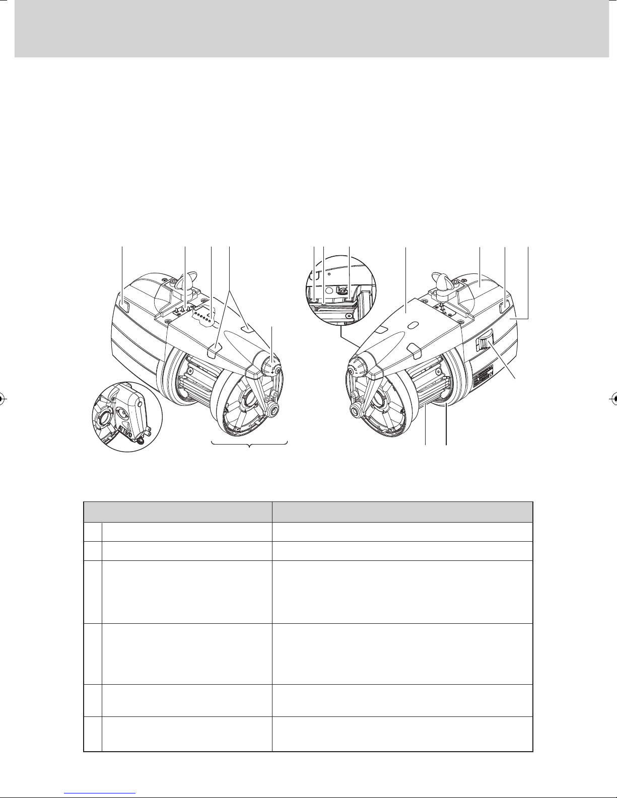
1.1 MAIN PARTS – CONTROL AND ADJUSTMENT POINTS
Main Parts:
1 • MOTOR 6 • OPTICAL OUTPUT SENSOR
2 • TOP PANEL 7 • POWER CABLE CONNECTION
3 • FLYWHEEL 8 • MAIN ELECTRONIC CONTROL BOARD
4 • YARN SPOOL BODY 9 • WINDING RESERVE CONTROL FEELER
5 • OUTPUT TENSIONER UNIT 10 • INPUT FEELER
1 - GENERAL FEATURES
0 – I SWITCH
SERIAL COMMUNICATION PORT
SIGNAL LAMPS
DIP SWITCH
ADJUSTING TWIST-KNOB
THREE-WAY CONNECTOR
• Switches the yarn feeder ON and OFF.
• Enables Pocket and PC interfacing.
• If yarn feeder is turned on and there are
no malfunctions, they will not light up.
• They will light up if any malfunction arises.
(consult paragraph 9 “Trouble shooting”).
• Enables adjustment of the optical sensor’s sensitivity range, reverse the direction of rotation,
self-calibrate magnetic sensors and perform the
termination of the serial bus (see chapter 4.1).
• Enable adjustment of the outbound yarn
tensioning.
• Enables connection of an output yarn feeler
(see chapter 1.8).
A
B
C
D
E
F
CONTROLS / ADJUSTMENTS FUNCTION
FOR FURTHER DETAILS CONCERNING
THE ATTIVO ELECTRONIC TENSIONS,
PLEASE GO TO CHAPTER 7
9
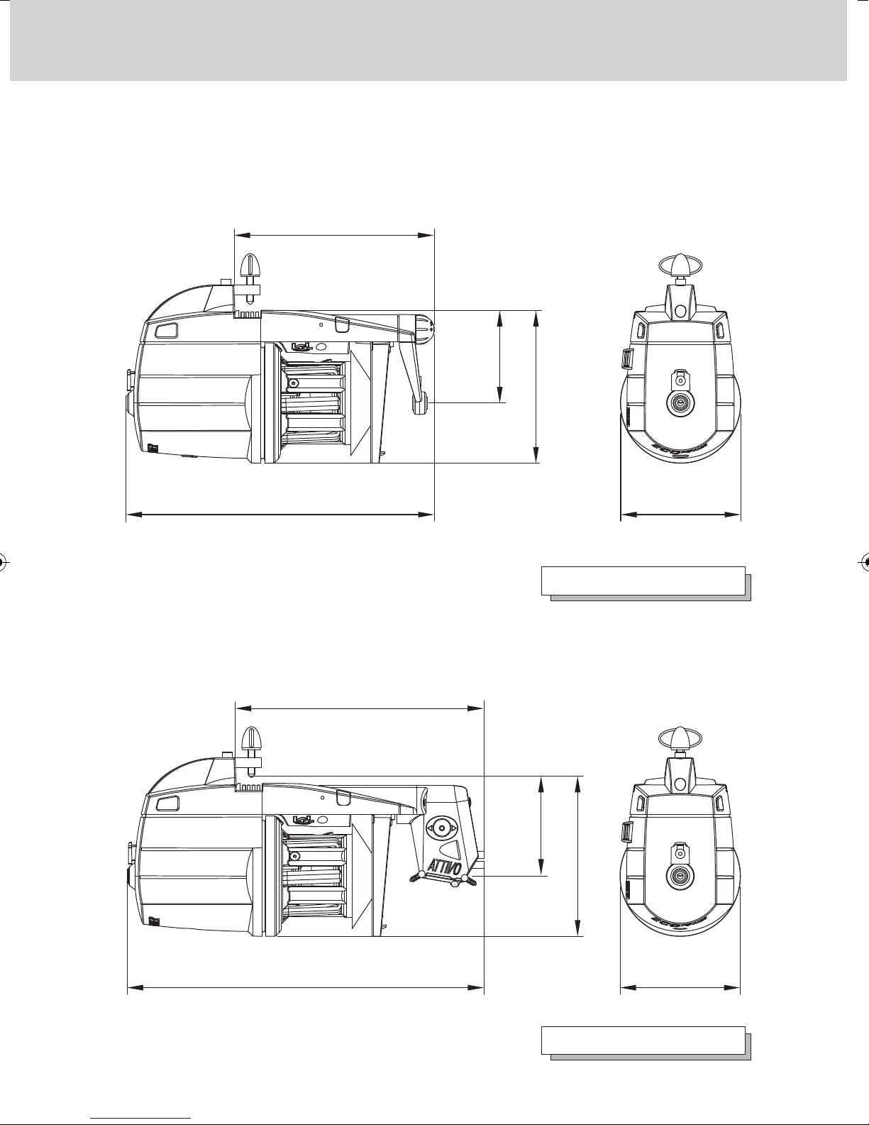
1 - GENERAL FEATURES
1.2 OVERALL DIMENSIONS
ECOPOWER featuring the TWM tension modulator
Weight 2.2 kg
Weight 2.3 Kg
ECOPOWER with ATTIVO electronic tensioner
166
77
127
256 Ø100
207
77
127
296 Ø100

10
1 - GENERAL FEATURES
1.3 INTENDED USE – TECHNICAL AND OPERATIONAL FEATURES
Intended Use:
ECOPOWER is a yarn feeder featuring separate coils, suitable for all types
of knitting machines or for textile machines requiring yarn feed-in with
constant tension.
Optimised operation is provided with yarn counts ranging from 500 den
(the thicker yarn counts) down to 10 den (fine yarn counts).
IMPROPER uses
Improper uses are all those uses which are not expressly indicated among
the design uses, namely:
- Working of yarns other than those specified
- Power supply of the machine not matching the specified value
- Use of the machine in an explosive atmosphere.
Operational features:
• Automatic speed adjustment designed to cover the machine's yarn quantity
requirements.
• Spool body winding reserve control by means of a magnetic feeler system.
• Yarn feeder and machine stop function if no yarn is detected at the feeder's
yarn input (broken yarn or empty yarn bobbin).
• Kit KLS (Optional):
Feeder and machine stop function when no yarn is found on feeder outlet
without using mechanical sensors (yarn broken or out of the needles).
• The option of being able to fit on various tensioning devices based on the
type of yarn actually being used, at both the feeder's inlet and outlet.
• Either vertical set-up or horizontal set-up assembly option, selectable
based on requirements.
• Real-time detection and display function of the yarn consumption related to
each machine feed
• ATTIVO electronic tensioner (optional). The operator sets the desired
output tension, and the system will maintain it, to avoid all tension changes
depending on the yarn, the bobbin and the like issues.
Technical specifications:
• Power supply by means of a direct connection with the machine, or through
a power supply box that is supplied separately by L.G.L. Electronics.
Power supply voltage data: V = 42-48 VAC Three-phase Hz = 50/60 (AC Version)
V = 57 VDC (DC Version)
• Automatic yarn input speed control provided up to a maximum of
1000 m/min.
• Coil separation feature fixed at 1 mm.
11
1 - GENERAL FEATURES
1.4 HANDLING AND STORAGE INSTRUCTIONS
Never pick the yarn feeder up by its yarn spool body, by its top
panel or by its tensioning unit.
The yarn feeder is supplied in an appropriate polystyrene casing;
please store the casing for use during any future handling.
1.5 INPUT FEELER
The yarn feeder features an input
feeler that provides the following
function:
• "Machine stop" function:
this function stops both the feeder
and the machine if no yarn is
detected at feeder input (broken
yarn or empty yarn spool).
Caution: the machine will not stop if the feeder comes to a halt.
The machine stop signal is operative only if the signal lamps are ON.
input feeler
YES NO
• Permanent magnet synchronous motor.
• Motor data:
Maximum power: 35 W
• Equivalent continuous A-weighted sound pressure level at maximum
speed: >70 dB (A)
• Operation and storage conditions:
- Room temperature: from +10 to +40 °C
- Maximum humidity: 80%
12
1 - GENERAL FEATURES
1.6 OPTICAL OUTPUT SENSOR
The optical sensor featured by the yarn feeder provides automatic speed
adjustment based on the quantity of yarn needed by the machine. For very
fine yarn count processing (lower than 40 den), the sensor requires DIP
SWITCH settings (paragraph 4 refers).
1.7 YARN SPOOL BODY WINDING RESERVE CONTROL FEELER
The magnetic sensor that the yarn feeder is provided with has the functionof
monitoring the yarn winding reserve on the spool body.
Output sensor
(photocell)
Winding reserve
control feeler
13
1 - GENERAL FEATURES
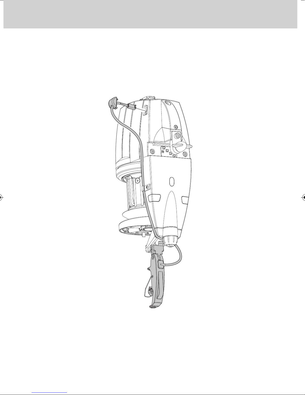
1.8 YARN OUTPUT DETECTION FEELER
The assembly of this detection feeler onto the feeder output, enables the
machine to receive a stop signal that is relayed by the feeder when it detects
output yarn snaps/breaks.
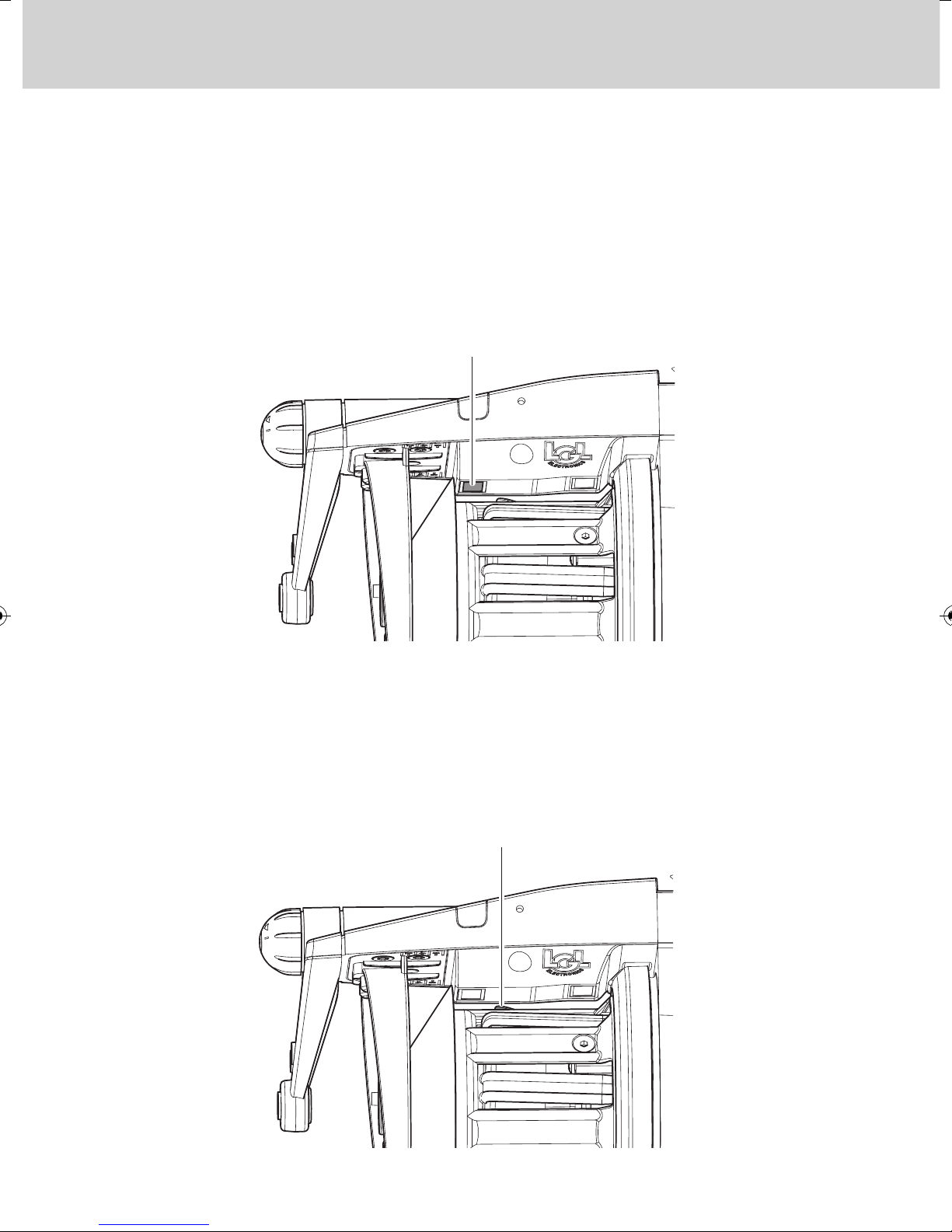
Installation: once the feeler has been fixed onto the feeder using the nuts and
bolts provided on the support bracket, connect up the wire with the three-way
connector located on the feeder housing.
F
C
G
IL
G
F
C
H
F
G
H
14
2 - INSTALLATION AND START-UP
2.1 YARN FEEDER INSTALLATION AND START-UP
N.B.: Yarn feeders that are moved from warehouse storage into a
warmer knitting mill environment may develop condensation; please
wait until they are completely dry before connecting them up.
Failure to do so may damage the electronic components.
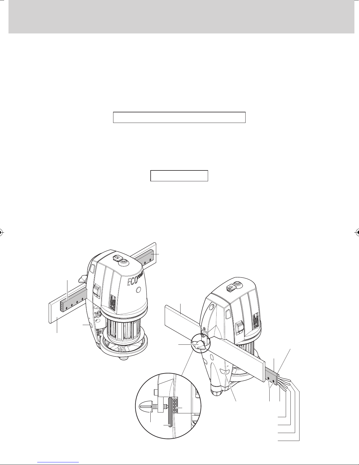
For installation of the yarn feeder onto the machine, proceed as follows:
VERTICAL SET-UP VERSION
Fix the feeder onto the appropriate support plate (F) and fit in the power supply
cable strip (G) as well; tighten in grub screw (H) until the strip is punctured.
IMPORTANT: To avoid damaging the electronic components, the installation sequence illustrated in the figures below must absolutely be
complied with exactly.
The brown cable (I) must be kept facing the signal lamps (C) (if the cable strip
is supplied by LGL, the brown cable (I) can be identified by the arrows (L)
printed on the cable strip).
N.B.: Make sure that the support plate the yarn feeder is fixed onto is
provided with an earth connection, the same goes for the 48V AC threephase power supply transformer star-connection.
AC version
Grey strap
Grey strap
Brown
Yellow
Blue
Black
 Loading...