

LG-Ericsson LIP-8002, LIP-8002A Installer's Manual

IP Phone
Installer Guide
LIP-8002/8002A
SIP (Session Initiation Protocol)
iPECS
Please read this manual carefully before installation.
Retain it for future reference.

LIP-8002/8002A
iPECS Installer Guide
Copyright © 2010 LG-Ericsson Co., Ltd. All Rights Reserved
This material is copyrighted by LG-Ericsson Co., Ltd. Any unauthorized reproductions, use or disclosure of this material, or any part
thereof, is strictly prohibited and is a violation of Copyright Laws. LG-Ericsson reserves the right to make changes in specifications
at any time without notice. The information furnished by LG-Ericsson in this material is believed to be accurate and reliable, but is
not warranted to be true in all cases.
LG-Ericsson is a trademark of LG-Ericsson Co., Ltd.
All other brand and product names are trademarks or registered trademarks of their respective companies.
Regulatory and Safety Notices
LIP-8002/8002A
1. Radio Frequency Emissions
FCC Compliance statement:
This device complies with Part 15 rules. Operation is subject to the following two conditions;
1. This device may not cause harmful interference, and
2. This device must accept any interference received, including interference that may cause undesired operation.
This Equipment has been tested and found to comply with the limits for a Class B digital device, pursuant to Part 15 of the FCC
rules. These limits are designed to provide reasonable protection against harmful interference in a residential installation. This
equipment generates, uses and can radiate radio frequency energy and, if not installed and used in accordance with the
instructions, may cause harmful interference to radio communications. However, there is no guarantee that interference will not
occur in a particular installation. If this equipment does cause harmful interference to radio or television reception, which can b e
determined by turning the equipment off and on, the user is encouraged to try to correct the interference b y one of the following
measures:
Reorient or relocate the receiving antenna.
Increase the separation between the equipment and the receiver.
Connect the equipment into an outlet on a different circuit from that to which the receiver is connected
If problems persist, consult the dealer or an experienced radio/TV technician for help.
Canadian Compliance statement
:
This Class B digital apparatus complies with Canadian ICES-003.
Cet appareil numérique de la classe B est conforme à la norme NMB-003 du Canada.
This device complies with Class B Limits of Industry Canada. Operation is subject to the following two conditions;
1. This device may not cause harmful interference, and
2. This device must accept any interference received, including interference that may cause undesired operation.
European Union Declarations of Conformity
:
LG-Ericsson Co., Ltd. declares that the equipment specified in this document, which bears the “CE” mark, conforms
to the European Union Radio and Telecommunications Terminal Equipment Directive (R&TTE 1999/5/EC) including,
Electromagnetic Compatibility Directive (89/336/EEC) and
Low Voltage Directive (73/23/EEC)
The product fulfills the essential requirements of the harmonized standards shown above.
2. Product Safety Instructions
This product complies with and conforms to the following international Product Safety standards as applicable:
Safety of Information Technology Equipment, IEC 6095-1, including
Relevant national deviations as listed in Compliance with IEC for Electrical Equipment (IECEE)
Safety of Information Technology Equipment, CAN/CSA-C22.2 No. 60950-1/UL 60950-1
3. E-911 and use of the LIP-8002/8002A with Multi-Line Telephone System
Please note the use and operation of this phone as part of a multi-line telephon e system (MLTS) may be subject to
state and/or federal E-911 MLTS laws that require the MLTS to provide a caller’s telephone number, extension, and
physical location to applicable state and/or local emergency services when a caller initiates a 911 call. The MLTS
may not provide a caller’s telephone number, e xtension, or physical l ocation inform ation to emer gency services when
a caller dials 911, and compliance with state and/or federal E-911 MLTS laws is the sole responsibility of the
purchaser of this phone.
4. Privacy:
LIP-8002/8002A implements security and encryption technologies however, privacy of communic ations may not be
ensured when using this telephone.

LIP-8002/8002A
iPECS Installer Guide
ii
Care & Precautions:
Before connecting or using your new phone, take a moment to consider safety and reliability. Use common sense
when locating, connecting and using your IP Phone LIP-8002/8002A .
Locate on a dry level surface away. Keep the phone away from the edges of the surface to avoid the potential
of a fall.
Locate cables to avoid potential for damage. For example, do not locate under rugs or carpet as damage may
result from foot traffic or heavy objects. Also, do not locate cables between the desktop and walls where they
may be crushed, damaging the insulation.
Check the cables regularly and, if damage is noted, disconnect your phone. Contact your local representative
for a replacement.
Should liquid spill on the phone, disconnect the unit from power and the network.
Do not use during lightning storms. Lightning presents a potentially lethal shock hazard.
Clean the LIP-8002/8002A with a soft dry cloth; do not use liquid cleaners.
Always use caution when connecting to AC power. Use only with a properly grounded standard AC power
outlet.
What is new in this release?
Issue 1.00 2010, 08 first release

LIP-8002/8002A
iPECS Installer Guide
iii
Table of Contents
1. Introducing the LIP-8002/8002A ............................................................................1
1.1 The IP Phone LIP-8002/8002A Overview.........................................................................1
2. Installing the LIP-8002/8002A ................................................................................4
2.1 Connecting the IP Phone..................................................................................................4
2.2 Wall Mounting...................................................................................................................5
2.3 Provisioning the LIP-8002/8002A .....................................................................................6
3. Using the LCD Configuration Menu......................................................................8
3.1 Navigating the LCD Configuration Menu ........................................................................10
3.2 Entering Values with the Dial Pad and Softkeys.............................................................10
3.3 Lock/Unlock Configuration..............................................................................................10
3.4 Network Configuration ....................................................................................................12
3.4.1 Network Mode..........................................................................................................12
3.4.2 IP Address ...............................................................................................................12
3.4.3 Subnet Mask............................................................................................................13
3.4.4 Default Gateway......................................................................................................13
3.4.5 Primary DNS Address..............................................................................................14
3.4.6 Secondary DNS Address.........................................................................................15
3.4.7 MAC Address...........................................................................................................15
3.4.8 VLAN Settings .........................................................................................................16
3.4.8.1 VLAN Priority (LAN)
........................................................................................................ 16
3.4.8.2 VLAN ID (LA
N) ............................................................................................................... 16
3.4.8.3 VLAN Priority (PC)
.......................................................................................................... 17
3.4.8.4 VLAN ID (PC)..................................................................................................................18
3.5 SIP Configuration............................................................................................................18
3.5.1 SIP Configuration, Line Parameters........................................................................18
3.5.1.1 Call Server A
ddress........................................................................................................ 18
3.5.1.2 Proxy Port
....................................................................................................................... 19
3.5.1.3 Display Name..................................................................................................................19
3.5.1.4 Name
.............................................................................................................................. 20
3.5.1.5 Authentication User Name
.............................................................................................. 20
3.5.1.6 Authentication Password
................................................................................................ 21
3.5.1.7 Regis
tration Status..........................................................................................................22
3.5.2 SIP Configuration, General Parameters..................................................................22
3.5.2.1 Outbound Proxy
Address................................................................................................ 22
3.5.2.2 Outbound Proxy Port
...................................................................................................... 23
3.5.2.3 Back
up Proxy Address.................................................................................................... 23
3.5.2.4 Back
up Proxy Port.......................................................................................................... 24
3.5.2.5 Local UDP
Port............................................................................................................... 24
3.5.2.6 R
TP Start Port................................................................................................................. 24
3.5.2.7 Proxy Regis
tration .......................................................................................................... 25
3.5.2.8 Regis
ter Expires ............................................................................................................. 25
3.5.2.9 VMS Addres
s.................................................................................................................. 26
3.5.2.10 Domain
............................................................................................................................ 26
3.6 Phone Settings ...............................................................................................................27
3.6.1 LCD Contrast...........................................................................................................27
3.6.2 Ring Setting.............................................................................................................28
3.6.2.1 Default Ring T
ype ........................................................................................................... 28

LIP-8002/8002A
iPECS Installer Guide
iv
3.6.2.2 Trunk Ring Type.............................................................................................................. 28
3.6.3 Ringer Off ................................................................................................................29
3.6.4 Flexible Button Setting.............................................................................................29
3.6.5 Time Configuration ..................................................................................................30
3.6.5.1 SNTP
Server Address..................................................................................................... 30
3.6.5.2 T
ime Zone....................................................................................................................... 31
3.6.5.3 DST
Auto Adjustment...................................................................................................... 31
3.6.5.4 T
ime Format.................................................................................................................... 32
3.6.5.5 Date Format
.................................................................................................................... 32
3.6.6 S/W Update .............................................................................................................33
3.6.6.1 Provis
ioning Type............................................................................................................33
3.6.6.2 TFTP
Server Address..................................................................................................... 33
3.6.6.3 HTTPS Provis
ioning ....................................................................................................... 34
3.6.6.3.1 Provis
ioning URL ................................................................................................. 34
3.6.6.3.2 Username
............................................................................................................. 35
3.6.6.3.3 Pass
word.............................................................................................................. 35
3.6.6.3.4 HTTPS URL
DHCP Option Number..................................................................... 36
3.6.6.4 S/W Download Flag
........................................................................................................ 36
3.6.6.5 Config Downl
oad Flag .................................................................................................... 37
3.6.6.6 DHCP
Option.................................................................................................................. 37
3.6.7 Lock Outgoing Call ..................................................................................................38
3.6.8 Speed Number.........................................................................................................39
3.6.9 Key Tone..................................................................................................................39
3.6.10 Language.................................................................................................................39
3.7 Call Preferences .............................................................................................................40
3.7.1 Do Not Disturb.........................................................................................................40
3.7.2 Call Waiting..............................................................................................................40
3.7.3 Call Waiting Tone.....................................................................................................41
3.7.4 Call Hold Ringback..................................................................................................41
3.7.5 Message Waiting Tone.............................................................................................42
3.7.6 Auto Answer.............................................................................................................42
3.7.7 Caller ID Blocking....................................................................................................43
3.7.8 Anonymous Call Block............................................................................................. 43
3.8 Phone Book ....................................................................................................................43
3.8.1 Dialing from the Phone Book...................................................................................44
3.9 Default ............................................................................................................................44
3.10 Reboot............................................................................................................................44
4. Using Web Manager for Configuration...............................................................46
4.1 Login & Site Map ............................................................................................................46
4.2 VoIP Configuration..........................................................................................................48
4.3 LAN Configuration...........................................................................................................51
4.4 Call Preferences .............................................................................................................53
4.5 Dial Plan .........................................................................................................................55
4.5.1 Digit Map Table........................................................................................................55
4.6 Phone Information .........................................................................................................57
4.7 Phone Settings ...............................................................................................................58
4.8 Phone Book ...................................................................................................................60
4.9 Flexible Button................................................................................................................63

LIP-8002/8002A
iPECS Installer Guide
v
4.10 Call Log...........................................................................................................................64
4.11 Network Time Configuration...........................................................................................65
4.12 Upgrade Configuration....................................................................................................67
4.13 QoS Configuration..........................................................................................................69
4.14 Load Default ...................................................................................................................71
4.15 Reboot............................................................................................................................72
5. TroubleShooting...................................................................................................73
5.1 Information......................................................................................................................73
5.2 Troubleshooting Guide....................................................................................................74
Appendix A. Factory Default Configuration ..............................................................75
Appendix B. LIP-8002/8002A Specification ...............................................................79
Appendix C. Download LCD Messages.....................................................................80
Appendix D. Using the Configuration File.................................................................81
Appendix E. Dial Pad Mode ........................................................................................98
Appendix F. Auto Provisioning Routine.....................................................................99

LIP-8002/8002A
iPECS Installer Guide
1
1. Introducing the LIP-8002/8002A
1.1 The IP Phone LIP-8002/8002A Overview
The LG-Ericsson IP phone (LIP-8002/8002A) is Internet Protocol (IP) phones designed to
support hosted telephony services over a managed IP network. Based on the open standard
Session Initiation Protocol (SIP), LIP-8002/8002A interoperates and exchanges signaling
messages with SIP call servers, proxies and gateways to establish, maintain and terminate calls.
Real-time Transport Protocol (RTP) packets transport audio between end-points through the
service provider’s network.
Features available to the IP Phone when used with SIP call servers are similar to those of a
conventional business telephone. Features available for a given phone depend on the
configuration of the call server as well as configuration of the IP phone and include:
Anonymous call blocking
Auto answer
Call forward
Busy
No answer
Immediate
Call hold
Call hold ringback
Call logs
Missed
Incoming
Outgoing
Call Park
Call Pick-up
Directed
Group
Park pick-up
Call refusal
Call transfer
Call waiting
Caller Id blocking
Caller Id display
Click-to-call
Distinctive ring tones
Do Not Disturb (DND)
Hands-free dialing
Hotline/Warm-Line (Direct Call)
Last call return
Last number redial
LCD contrast control
Message wait with indicator lamp and tone
Mute
One-button Call Transfer
LIP-8002/8002A
iPECS Installer Guide
2
Phone Book
Private line
Private Hold
Speakerphone, full duplex
Speed dial buttons
Speed number dialing
Station-to-Station dialing
Volume control (handset, speakerphone, and ring)
3-Way conference
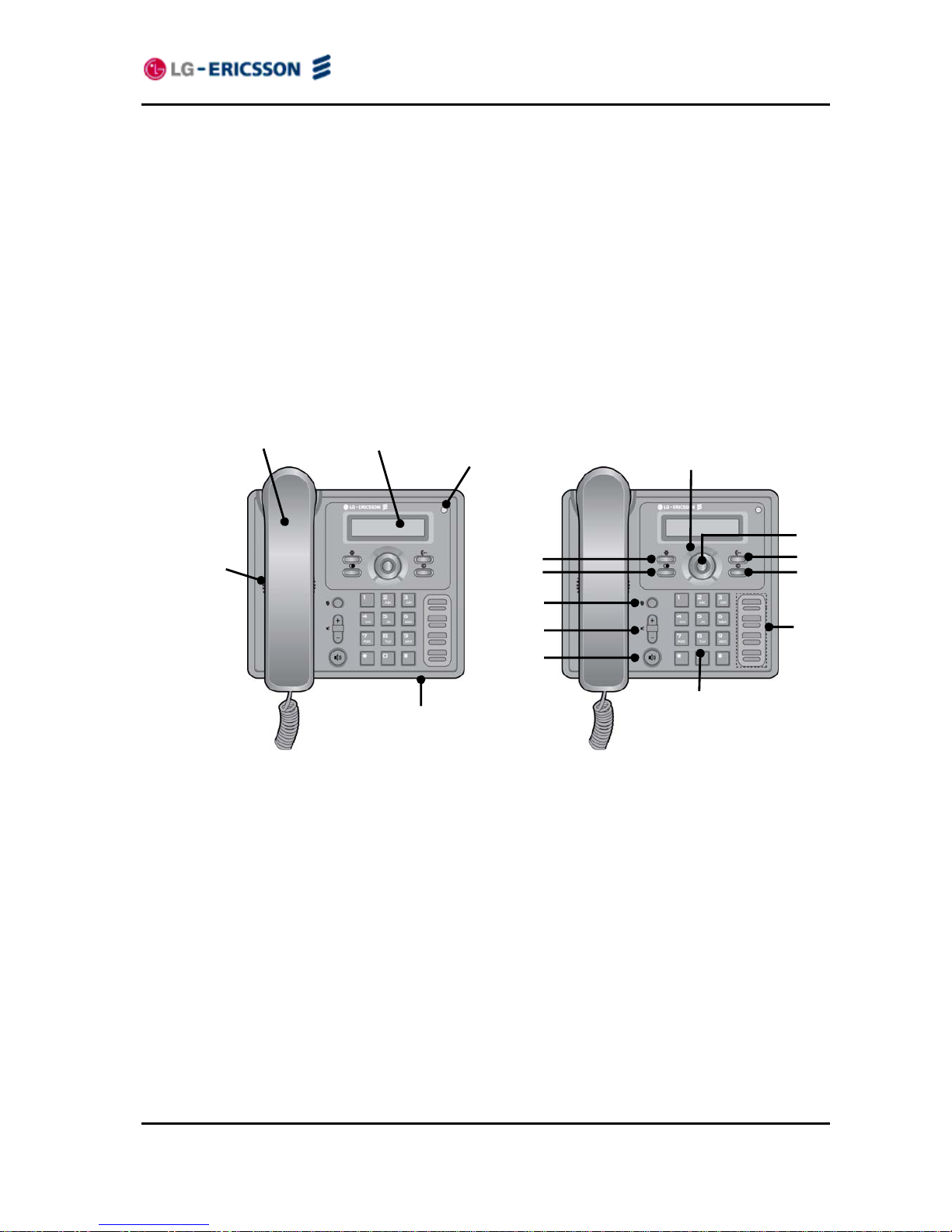
For ease of use, the LIP-8002/8002A is equipped with fixed buttons, flexible (programmable)
buttons, an LCD display, menu navigation buttons, and a dial pad. Figure 1.1-1illustrates these
elements of the LIP-8002/8002A.
Figure 1.1-1 LIP-8002/8002A
Handset
LCD(128x32)
MWI LED
Speaker
Microphone
9
10
11
1
2
3
4
5
6
7
8
LIP-8002/8002A
iPECS Installer Guide
3
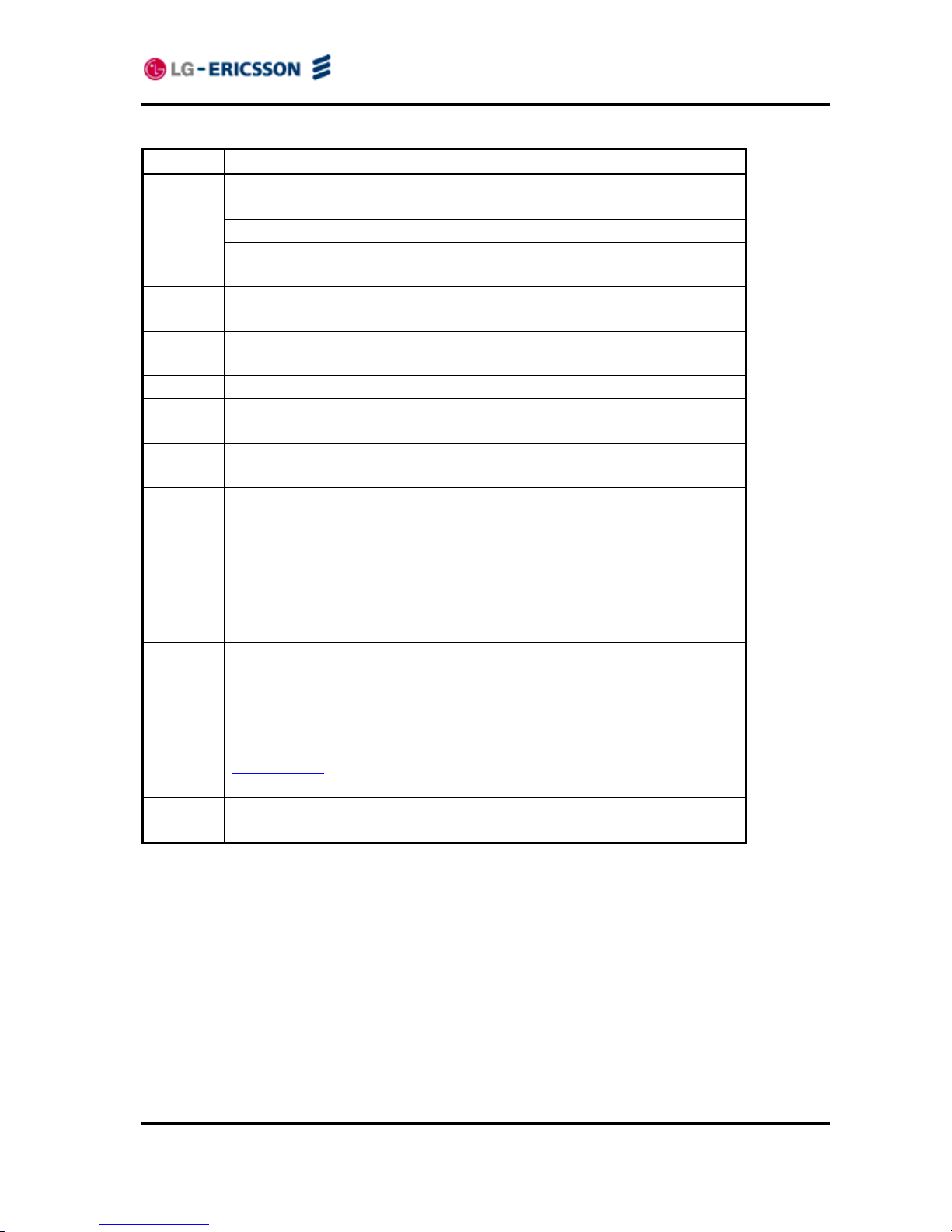
Number Function
Left button - Move to the previous menu in the settings menu.
Right button
Up button - When the phone is in the idle state, accesses the call log.
1
Down button - When the phone is in the idle state, accesses the
phonebook.
2
OK button - Select a current item or save a value in the settings menu.
Retrieve a hold Call button (In Hold State) - Use to retrieve a hold call.
3
Settings button - ‘Settings’ accesses and exits the menu for display
and changes to the IP Phone configuration.
4 Redial button - Use to dial the last number dialed.
5
Mute button - Toggle audio from the microphone to the connected
party On and Off.
6
Volume control button - Use to adjust Ring, Handset, and Speaker
volume.
7
Speakerphone button - Toggle the IP phone speakerphone On and
Off.
8
Mode button (In Editing State) - Use to switch the input mode can
accept an alphanumeric entry.
Forward button (In Idle State) - Use to set the call forwarding
configuration.
Transfer button (In Call State) - Use to transfer the current active call.
9
Delete button (In Editing State) - Use to delete a letter in front of the
cursor or clear an entire string.
Conference button (In Call State) – Use to initiate, cancel or join the
conference call.
10
Flexible buttons - Assign as feature in Phone configuration. Refer to
section 3.6.5 under Flexible Button Setting for instructions on defining
flexible buttons.
11
Dial pad buttons (In Editing State)- Use to dial a number, select a
menu item, or input a value.
LIP-8002/8002A
iPECS Installer Guide
4
2. Installing the LIP-8002/8002A
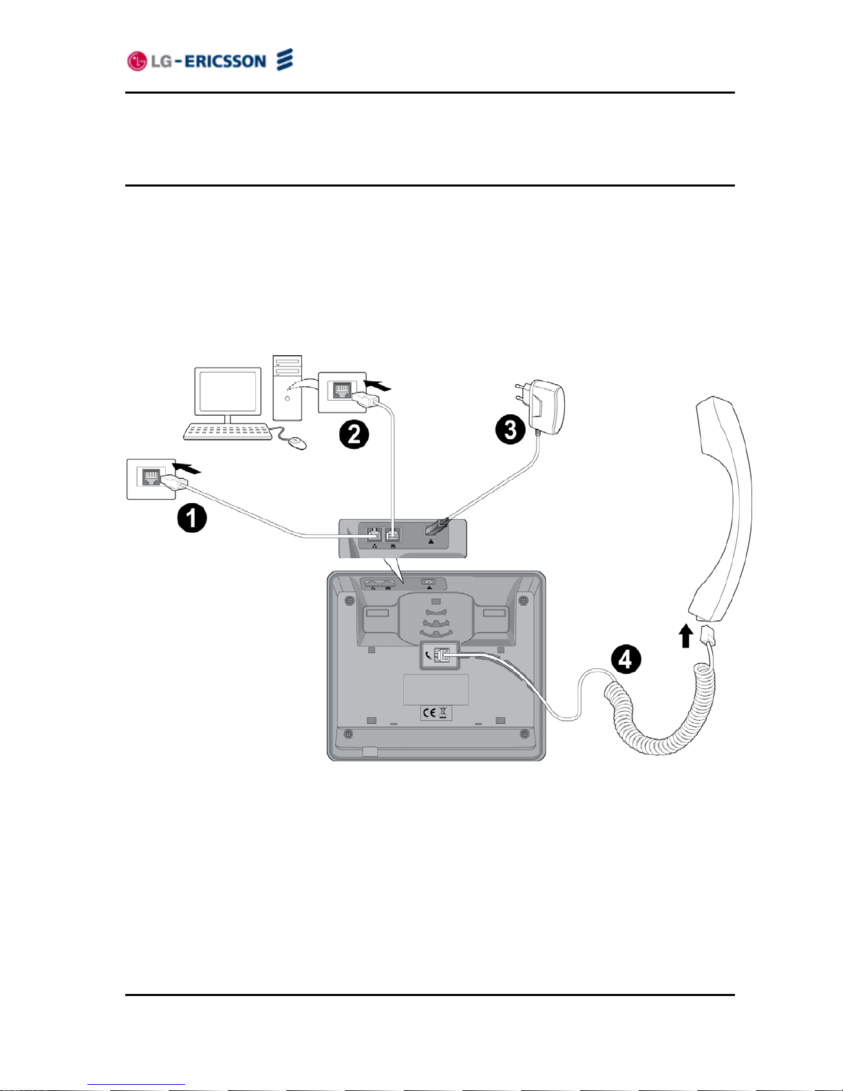
2.1 Connecting the IP Phone
The figure below shows the cable connections for your IP Phone. The LAN and desktop PC
connections employ standard Category 5 cables terminated with RJ-45 connectors. The LIP8002 supports PoE (Power over Ethernet) in accordance with the IEEE-802.1af standard. (The
LIP-8002A doesn’t support PoE and can use only the supplied adaptor.) When connected to a
PoE complaint LAN port, the IP Phone derives power from the port. If the LAN port does not
support PoE, use the AC/DC adaptor, available separately, for connection to power. The
handset connects to the base with the supplied standard handset coiled cord. Use the chart
below to make connections to the IP Phone.
Figure 2.1-1 IP Phone Connections
Wiring Chart
1 LAN Connect the IP Phone LAN port to the LAN wall jack with the provided LAN
cable.
2 PC Connect the IP Phone PC port to your desktop PC with an RJ-45 terminated
UTP-5 cable.
LIP-8002/8002A
iPECS Installer Guide
5
3 Power The LIP-8002 supports PoE. So, if the LAN port supports PoE, IEEE 802.3af
compliant, Class 2, the AC/DC adapter is not required. If not supported,
connect the IP Phone power port to the DC out of Power Adapter. Connect the
Power Adapter AC plug to an AC wall jack.
The LIP-8002A doesn’t support PoE. So, must connect the IP Phone power
port to the DC out of Power Adapter. Connect the Power Adapter AC plug to
an AC wall jack.
4 Handset Connect the Handset coiled cord to the IP Phone base and handset.
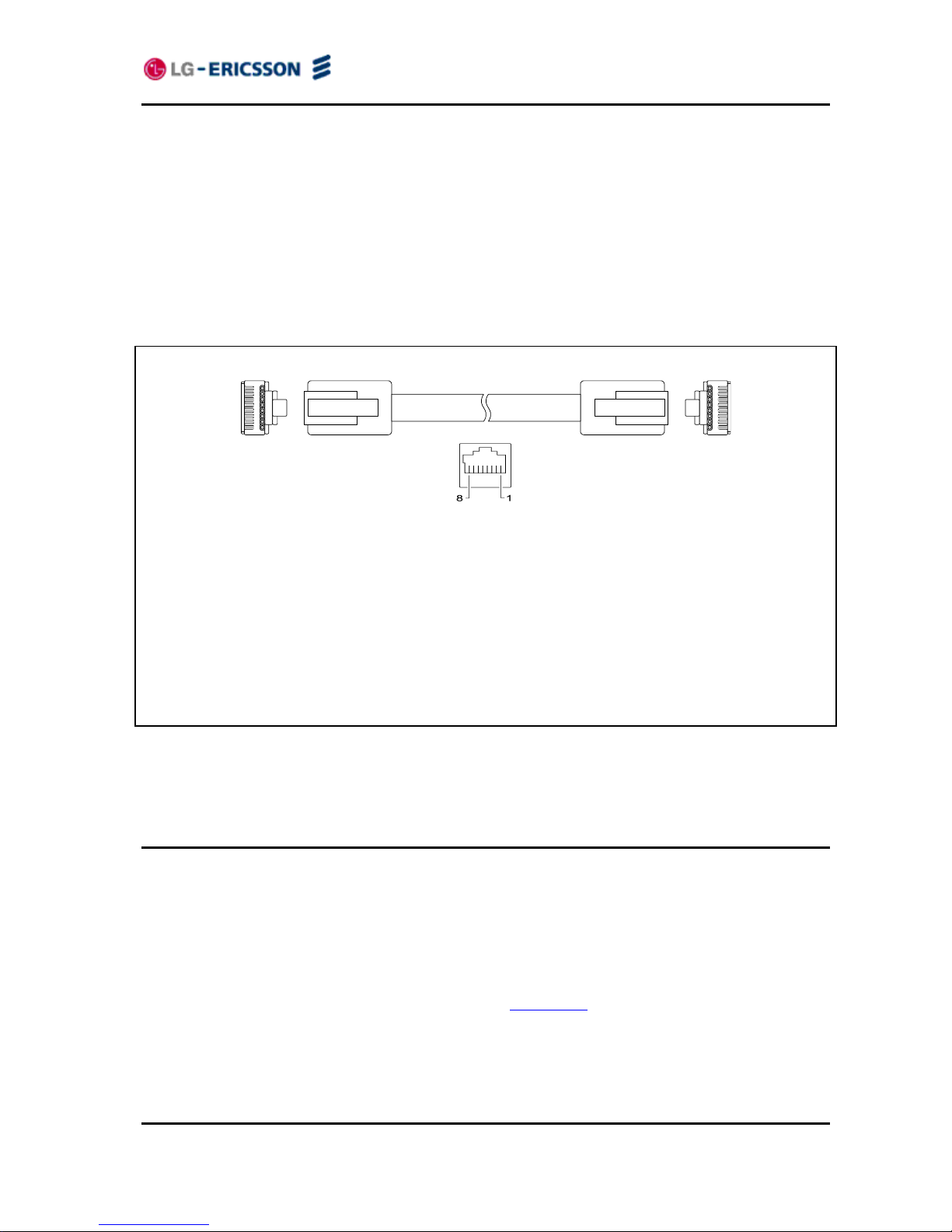
RJ-45 Pin Assignments
LAN port PC port
Pin 1 = TX+ Pin 1 = RX+
Pin 2 = TX- Pin 2 = RX Pin 3 = RX+ Pin 3 = TX+
Pin 4 = optional: 48V (or GND) Pin 4 = No connection
Pin 5 = optional: 48V (or GND) Pin 5 = No connection
Pin 6 = RX- Pin 6 = TX Pin 7 = optional: GND (or 48V) Pin 7 = No connection
Pin 8 = optional: GND (or 48V) Pin 8 = No connection
Figure 2.1-2 RJ-45 Terminations
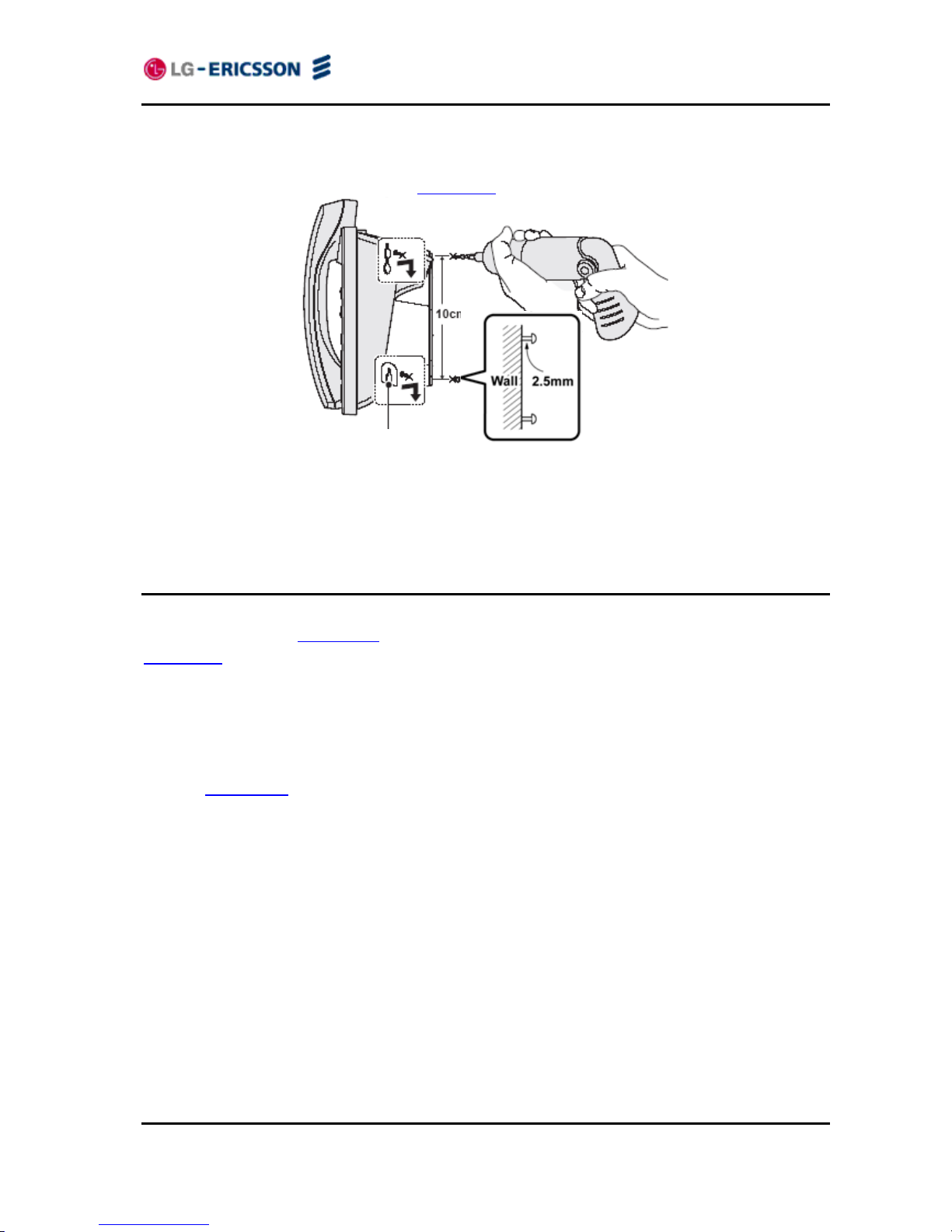
2.2 Wall Mounting
The LIP-8002/8002A incorporates wall mounting in the base of the phone housing. Using the
instructions below and Figure 2.2-1, wall mount the LIP-8002/8002A phone.
Mark and drill two 7 mm holes for plastic wall anchors with a vertical separation of 10 cm.
Insert two (2) anchors into the holes, then insert and tighten the two (2) screws leaving about
2.5 mm exposed. Refer to Figure 2.2-1.
Attach all wiring to the IP Phone as described in section 2.1
.
Slide the IP Phone over the screws and assure the phone is secure. Note it may be
necessary to remove the phone and tighten or loosen the screws for a secure mounting.
Also note, the Foot Stand must not be attached to the IP Phone when wall mounting.
LIP-8002/8002A
iPECS Installer Guide
6
Remove the Handset hook from the phone as shown in the figure below. Reverse the hook
and re-install in the IP Phone so that the hook catches the groove in the handset receiver.
Complete all wiring as described in section 2.1
.
Figure 2.2-1 LIP-8002/8002A Wall Mount Installation
2.3 Provisioning the LIP-8002/8002A
LIP-8002/8002A supports ‘plug and play’ installation employing the automated provisioning
process described in Appendix F
. After connecting to the LAN, desktop PC and power, refer to
section 2.1
, the IP phone retrieves LAN settings including IP address, subnet mask and default
gateway address from the local DHCP (Dynamic Host Control Protocol) server. In addition, the
IP phone requests address information for the provisioning server where configuration and
software files are maintained. The IP phone downloads the configuration and, if required,
software files from the provisioning server. When complete, the IP phone automatically
registers and subscribes for SIP call services using the information from the configuration files.
Refer to Appendix D
for more details.
LIP-8002/8002A incorporates means for manual configuration when the automated process is
not fully available. As a minimum, the LIP-8002/8002A requires the information below for
proper operation. When not assigned through the automated provisioning process, manual
entry of the below parameters is required for proper operation.
- SIP parameters including:
o SIP call server IP address
o Name (SIP user id)
o Authentication user name
o Authentication password
In addition using static IP addressing requires manual entry of the following IP network
configuration data.
o IP address of the IP phone

LIP-8002/8002A
iPECS Installer Guide
7
o Default gateway address
o Subnet mask
Two methods are available for manual configuration. The LCD Configuration Menu permits
local configuration using the dial pad, see section 3
The second method employs the LIP8002/8002A Web Manager, which allows access to the IP phone configuration using a Web
browser, see section 4
. Manual configuration permits assignment of all parameters required to
gain full operation of the IP phone. However, manual configuration is time consuming and is
intended only to augment the automated process and to allow customizing user preferences.

LIP-8002/8002A
iPECS Installer Guide
8
3. Using the LCD Configuration Menu
This chapter provides detailed information to configure the LIP-8002/8002A using the LCD
Configuration Menu. The LCD displays the configuration menu. The dial pad select menu
items and input values. A configuration session begins by pressing the Settings (
) button,
which accesses the LCD Configuration Menu shown in Figure 3-1
. Select the desired menu
item using one of the following methods:
Use the dial pad to input the menu item number. This is the digit displayed in front of the item
or
Navigate with navigation buttons to highlight the item and select with the OK button.
Configuration Menu
1.Network Configuration
2.SIP Configuration
3.Phone Settings
4.Call Preferences
5.Directory
6.Set to Default
7.Lock/Unlock Config
8.Information
9.Reboot
Figure 3-1 LCD Configuration Main Menu
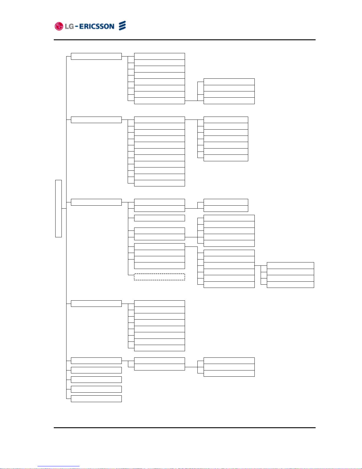
When the desired parameter is reached, enter data with the dial pad or select values. Refer to
Figure 3-2
for the complete menu.
Sections 3.1
to 3.3 give general information on use of the LCD Menu. The remaining
paragraphs of this section give descriptive and procedural information for each parameter of the
menu. Information is organized to follow the structure of the menu as shown in Figure 3-2
.
LIP-8002/8002A
iPECS Installer Guide
9
Figure 3-2 LCD Configuration Menu
1. Network Configuration
2. SIP Configuration
1. Network Mode
2. IP Address
3. Subnet Mask
4. Default Gateway
5. Primary DNS Address
6. Secondary DNS Address
7. MAC Address
1. Call Server Address
3. Display Name
4. Name
5. Auth. Username
6. Auth. Password
1. SNTP Server Address
2. Time Zone
2. TFTP Server Address
4. S/W Download Flag
5. Config Download Flag
1. Phone Book
2. Call Log
1. Missed Calls
2. Received Calls
3. Placed Calls
6. Set to Default
7. Lock/Unlock Config
8. Information
9. Reboot
2. Outbound Proxy Addr.
4. Backup Proxy Address
8. Proxy Registration
9. Register Expires
10. VMS Address
4. Call Preferences 1. Do Not Disturb
7. Caller ID Blocking
8. Anonymous Call Block
3. Call Waiting Tone
4. Call Hold Ringback
5. Msg Waiting Tone
6. Auto Answer
3. DST Auto Adjustment
5. Directory
1. LCD Contrast
2. Ring Setting
3. Ringer Off
4. Flexible Key Setting
5. Time Configuration
6. S/W Update
3. Phone Settings
Configuration Menu
2. Call Waiting
7. Reg. Status
2. Proxy Port
3. Outbound Proxy Port
5. Backup Proxy Port
6. Local UDP Port
7. RTP Start Port
8. VLAN Settings
1. VLAN Priority (LAN)
3. VLAN Priority (PC)
4. VLAN ID (PC)
2. VLAN ID (LAN)
1. Provisioning Type
3. HTTPS Provisioning 1. Provisioning URL
2. Username
3. Password
7. Lock Outgoing Call
8. Speed Number
11. Domain
4. Time Format
6. DHCP Option
5. Date Format
4. DHCP Option Number
1. Default Ring Type
1. Line Configuration
9. Key Tone
Appears when
language xmls exist
10. Language
2. Trunk Ring Type

LIP-8002/8002A
iPECS Installer Guide
10
3.1 Navigating the LCD Configuration Menu
The IP phone must be idle to access the configuration menu and may be password protected
(Locked). If locked, advanced configuration parameters can be viewed, however, data entry is
not possible. Refer to section
3.3.
To access the configuration menu:
Press the Settings (
) button.
To select an item:
Dial the digit associated with the menu item or
Use the Up/Down navigation buttons to move the cursor to the item, then press the OK
button.
To return to a previous branch in the menu:
Press the Left navigation button.
To exit the configuration menu:
Press the Settings (
) button.
3.2 Entering Values with the Dial Pad and Softkeys
Use the dial pad to input numbers, letters, special characters, and a period. Selecting the Mode
button switches the dial pad mode. The dial pad mode displays in the upper-right corner as
for numeric,
for upper case characters and for lower case characters. Appendix E.
defines the relationship between the dial pad digits and characters.
To enter characters with the dial pad, use the digit with the desired character. Press the same
digit repeatedly until the desired character appears in the LCD. After entering a character,
pause to allow the cursor to move to next character position.
Other special entries include:
- To enter a period or dot (for example, to input an IP address), press asterisk, , on the
dial pad.
To delete a letter in front of the cursor, press the Delete button.
- To clear an entire string, press the Delete button for a while.
Prior to saving an entry, you may discard changes by pressing the Left navigation button to
move to the previous menu, or press the Settings (
) button to exit the Settings menu.
3.3 Lock/Unlock Configuration
The LCD Configuration Menu can be protected for security using a four to eight digit password.
With a password assigned, exiting the LCD Menu automatically locks the menu. Configuration

LIP-8002/8002A
iPECS Installer Guide
11
data displays while the menu is locked however, the menu must be unlocked using the
password in order to change advanced parameters. Parameters under the ‘Phone Settings’
item listed below are not subject to the lock feature, allowing the user access without the need
to enter a password.
- LCD Contrast
- Ring Type
- Ringer Off
- Flexible Button settings
- Time Configuration
- Speed Number Dialing
- Key Tone
- Language
With the menu locked, (padlock icon) appears in the settings menu.
To assign a password:
Press the Settings (
) button.
Press the
digit, or move the cursor to 7.Lock/Unlock Config using the navigation
buttons and press the OK button. If a password has been previously established, the
previous password must be entered and press the OK button.
Press the
digit, or move the cursor to 1.Change Password using the navigation buttons
and press the OK button. 2. Remove Password menu removes the assigned password.
Enter your new password using the dial pad and press the OK button. A password is
composed of four (4) to eight (8) digits.
To confirm your password, input the new password again and press the OK button.to save
your entry.
Move to another parameter with the navigation buttons and continue the session or press the
Settings (
) button to exit the configuration session, which will lock the LCD Menu
automatically if a password is assigned.
To unlock the LCD Menu:
Press the Settings (
) button.
Press the
digit, or move the cursor to 7.Lock/Unlock Config using the navigation
buttons and press the OK button.
Enter the password (4 to 8 digits) and press the OK button.
Press the
digit, or move the cursor to 3.Unlock Menu using the navigation buttons and
press the OK button, the Unlocked message appears for approximately 2 seconds and the
LCD Menu is unlocked.
Move to another parameter with the navigation buttons and continue the session or press the
Settings (
) button to exit the configuration session.
With a password assigned, exiting the LCD Configuration Menu automatically locks the
menu.
Entering an invalid password returns an error message followed by the “Enter
Password” display.
LIP-8002/8002A
iPECS Installer Guide
12
3.4 Network Configuration
Under Network Configuration are the Network mode (DHCP or static), various IP addresses,
DNS (Domain Name Service), and other LAN parameters. In addition, the IP phone MAC
(Media Access Control) address can be viewed. When using the WiFi Module refer to section 5
for the Network Configuration sub-menus.
Changing network parameters requires a reboot of the IP phone; when you exit the LCD
Configuration Menu, you will receive a reboot notice. The IP phone must reboot to
utilize the new values entered.
3.4.1 Network Mode
The IP phone is capable of obtaining all of its IP configuration data from a DHCP server. When
a DHCP server is not available, static addressing is used for the Network Mode. Selecting static
addressing requires manual entry of other IP network parameters including:
- IP address of the phone
- Default gateway IP address
- Subnet mask
- DNS address
To set the Network Mode:
Press the Settings (
) button. If the LCD Menu is locked, use the unlock procedure. Refer
to section 3.3
.
Press the
digit, or move the cursor to 1.Network Configuration using the navigation
buttons and press the OK button.
Press the
digit, or move the cursor to 1.Network Mode using the navigation buttons and
press the OK button.
Select the Network Mode using the Up/Down navigation buttons and press the OK button to
save your selection.
Move to another parameter with the navigation buttons and continue the session or press the
Settings (
) button to exit the configuration session.
An asterisk, , is displayed in front of the current selection.
Changing the Network Mode requires a reboot of the IP phone; when you exit the LCD
Configuration Menu, you will receive a reboot notice. The IP phone must reboot to
utilize the new values entered.
3.4.2 IP Address
Selecting static addressing for the Network mode requires manual entry of an IP address for the
IP phone. The IP phone requires a valid available IP address for proper operation.
To set the IP Address:
Press the Settings (
) button. If the LCD Menu is locked, use the unlock procedure. Refer
to section 3.3
.
LIP-8002/8002A
iPECS Installer Guide
13
Press the digit, or move the cursor to 1.Network Configuration using the navigation
buttons and press the OK button.
Press the
digit, or move the cursor to 2.IP Address using the navigation buttons and
press the OK button.
Input the IP Address using the dial pad and press the OK button to save your entry.
Move to another parameter with the navigation buttons and continue the session or press the
Settings (
) button to exit the configuration session.
The IP Address can be changed only in static mode and not if DHCP mode is active. In
DHCP mode, the IP phone retrieves an IP address from the DHCP server.
Changing the IP Address requires a reboot of the IP phone; when you leave the menu,
you will receive a reboot notice. The IP phone must reboot to utilize the new values
entered.
3.4.3 Subnet Mask
Selecting static addressing for the Network mode requires manual entry of a subnet mask for
the IP phone. The IP phone requires a valid subnet for proper operation.
To enter the Subnet Mask:
Press the Settings (
) button. If the LCD Menu is locked, use the unlock procedure. Refer
to section 3.3
.
Press the
digit, or move the cursor to 1.Network Configuration using the navigation
buttons and press the OK button.
Press the
digit, or move the cursor to 3.Subnet Mask using the navigation buttons and
press the OK button.
Input the Subnet Mask using the dial pad and press the OK button to save your configuration.
Move to another parameter with the navigation buttons and continue the session or press the
Settings (
) button to exit the configuration session.
The Subnet Mask can be changed only in static mode and not if DHCP mode is active.
In DHCP mode, the IP phone retrieves a subnet mask from the DHCP server.
Changing the Subnet Mask requires a reboot of the IP phone; when you leave the
menu, you will receive a reboot notice. The IP phone must reboot to utilize the new
values entered.
3.4.4 Default Gateway
Selecting static addressing for the Network mode requires manual entry of a default gateway
address for the IP phone. The IP phone requires a valid default gateway address for proper
operation.
To assign the Default Gateway address:
LIP-8002/8002A
iPECS Installer Guide
14
Press the Settings ( ) button. If the LCD Menu is locked, use the unlock procedure. Refer
to section 3.3
.
Press the
digit, or move the cursor to 1.Network Configuration using the navigation
buttons and press the OK button.
Press the
digit, or move the cursor to 4.Default Gateway using the navigation buttons
and press the OK button.
Input the Default Gateway IP address using the dial pad and press the OK button to save
your entry.
Move to another parameter with the navigation buttons and continue the session or press the
Settings (
) button to exit the configuration session.
The Default Gateway address can be changed only in static mode and not if DHCP
mode is active. In DHCP mode, the IP phone retrieves a default gateway address from
the DHCP server.
Changing the Default Gateway address requires a reboot of the IP phone; when you
leave the menu, you will receive a reboot notice. The IP phone must reboot to utilize
the new values entered.
3.4.5 Primary DNS Address
Using an FQDN (Fully Qualified Domain Name) for any of the servers in the IP phone
configuration requires entry of a primary DNS IP address. The IP phone contacts the primary
DNS server to resolve the FQDN to an IP address.
To assign the Primary DNS Address:
Press the Settings (
) button. If the LCD Menu is locked, use the unlock procedure. Refer
to section 3.3
.
Press the
digit, or move the cursor to 1.Network Configuration using the navigation
buttons and press the OK button.
Press the
digit, or move the cursor to 5.Primary DNS Address using the navigation
buttons and press the OK button.
Input the Primary DNS Address using the dial pad and press the OK button to save your
entry.
Move to another parameter with the navigation buttons and continue the session or press the
Settings (
) button to exit the configuration session.
The Primary DNS address can be changed only in static mode and not if DHCP mode is
active. In DHCP mode, the IP phone retrieves a Primary DNS address from the DHCP
server.
Changing the Primary DNS address requires a reboot of the IP phone; when you leave
the menu, you will receive a reboot notice. The IP phone must reboot to utilize the new
values entered.

LIP-8002/8002A
iPECS Installer Guide
15
3.4.6 Secondary DNS Address
With an FQDN assigned as any of the servers in the IP phone configuration, the IP phone
contacts the primary DNS server to resolve the FQDN to an IP address. Should the primary not
respond, the IP phone contacts a secondary DNS for FQDN resolution. This is an optional but
recommended setting.
To assign the Secondary DNS Address:
Press the Settings (
) button. If the LCD Menu is locked, use the unlock procedure. Refer
to section 3.3
.
Press the
digit, or move the cursor to 1.Network Configuration using the navigation
buttons and press the OK button.
Press the
digit, or move the cursor to 6.Secondary DNS Address using the navigation
buttons and press the OK button.
Input the Secondary DNS Address using the dial pad and press the OK button to save your
entry.
Move to another parameter with the navigation buttons and continue the session or press the
Settings (
) button to exit the configuration session.
The Secondary DNS address can be changed only in static mode and not if DHCP
mode is active. In DHCP mode, the IP phone retrieves a Secondary DNS address from
the DHCP server.
Changing the Secondary DNS Address requires a reboot of the IP phone; when you
leave the menu, you will receive a reboot notice. The IP phone must reboot to utilize
the new values entered.
3.4.7 MAC Address
IEEE specifications require manufacturers of data equipment to store a unique 6-byte MAC or
Ethernet address in the permanent memory of each network device.
To view the MAC Address:
Press the Settings (
) button.
Press the
digit, or move the cursor to 1.Network Configuration using the navigation
buttons and press the OK button.
Press the
digit, or move the cursor to 7.MAC Address using the navigation buttons and
press the OK button.
View the MAC Address of the IP phone.
Move to another parameter with the navigation buttons and continue the session or press the
Settings (
) button to exit the configuration session.
LIP-8002/8002A
iPECS Installer Guide
16
3.4.8 VLAN Settings
VLAN settings define the Ethernet frame priority and VLAN identification in accordance with
IEEE 802.1p/Q standards. Separate VLAN tags are assigned for the IP Phone PC port and the
LAN (voice) port. With a VLAN Id assigned, only frames with the assigned Id are accepted, and
all SIP and voice frames sent by the LIP-8002/8002A include the VLAN Id assigned to the LAN
port.
For proper operation, other network elements (LAN switches and default gateway) must
support and be configured with proper VLAN parameters.
Changing the VLAN parameters requires a reboot of the IP phone; when you leave the
menu, you will receive a reboot notice. The IP phone must reboot to utilize the new
values entered.
3.4.8.1 VLAN Priority (LAN)
The VLAN Priority (LAN) establishes the priority for Ethernet frames from the LIP-8002/8002A
voice port including signaling and voice packets. Setting the VLAN ID to zero (0) disables VLAN
framing and the IP Phone uses only standard Ethernet frames.
To assign VLAN Priority for the LAN (voice) port:
Press the Settings (
) button. If the LCD Menu is locked, use the unlock procedure. Refer
to section 3.3
.
Press the
digit, or move the cursor to 1.Network Configuration using the navigation
buttons and press the OK button.
Press the
digit, or move the cursor to 8.VLAN Settings using the navigation buttons and
press the OK button.
Press the
digit, or move the cursor to 1.VLAN Priority (LAN) using the navigation
buttons and press the OK button.
Input the VLAN Priority for the LAN port using the dial pad and press the OK button to save
your entry.
Move to another parameter with the navigation buttons and continue the session or press the
Settings (
) button to exit the configuration session.
Changing the VLAN Priority requires a reboot of the IP Phone; when you leave the
menu, you will receive a reboot notice. The IP Phone must reboot to utilize the new
values entered.
The recommended value for VLAN Priority (LAN) port is 5.
To disable VLANs, assign the VLAN ID as zero (0).
3.4.8.2 VLAN ID (LAN)
The VLAN ID (LAN) assigns the identification for Ethernet frames for the IP Phone voice port
including signaling and voice payloads. Setting the VLAN ID to zero (0) disables the VLAN
framing and the IP Phone uses only standard Ethernet frames.
LIP-8002/8002A
iPECS Installer Guide
17
To assign the VLAN ID for the LAN (voice) port:
Press the Settings (
) button. If the LCD Menu is locked, use the unlock procedure. Refer
to section 3.3
.
Press the
digit, or move the cursor to 1.Network Configuration using the navigation
buttons and press the OK button.
Press the
digit, or move the cursor to 8.VLAN Settings using the navigation buttons and
press the OK button.
Press the
digit, or move the cursor to 2.VLAN ID (LAN) using the navigation buttons and
press the OK button.
Input the VLAN ID for the LAN port using the dial pad and press the OK button to save your
entry.
Move to another parameter with the navigation buttons and continue the session or press the
Settings (
) button to exit the configuration session.
Changing the VLAN ID requires a reboot of the IP Phone; when you leave the menu,
you will receive a reboot notice. The IP Phone must reboot to utilize the new values
entered.
To disable VLANs, assign the VLAN ID as zero (0).
3.4.8.3 VLAN Priority (PC)
The VLAN Priority (PC) establishes the priority for Ethernet frames for the IP Phone PC port.
Setting the VLAN ID to zero (0) disables VLAN framing and the IP Phone uses only standard
Ethernet frames.
To assign the VLAN Priority for the PC port:
Press the Settings (
) button. If the LCD Menu is locked, use the unlock procedure. Refer
to section 3.3
.
Press the
digit, or move the cursor to 1.Network Configuration using the Up/Down
navigation buttons and press the OK button.
Press the
digit, or move the cursor to 8.VLAN Settings using the navigation buttons and
press the OK button.
Press the
digit, or move the cursor to 3.VLAN Priority (PC) using the navigation buttons
and press the OK button.
Input the VLAN Priority for the PC p ort using the dial pad and press the OK button to save
your entry.
Move to another parameter with the navigation buttons and continue the session or press the
Settings (
) button to exit the configuration session.
Changing the VLAN priority for the PC port requires a reboot of the IP Phone; when you
leave the menu, you will receive a reboot notice. The IP Phone must reboot to utilize
the new values entered.
To disable VLANs, assign the VLAN ID as zero (0).
The recommended value for the VLAN Priority for the PC port is 3.
LIP-8002/8002A
iPECS Installer Guide
18
3.4.8.4 VLAN ID (PC)
The VLAN ID (PC) assigns the identification for Ethernet frames for the IP Phone PC port.
Setting the VLAN ID to zero (0) disables VLAN framing and the IP Phone uses only standard
Ethernet frames.
To assign the VLAN ID (PC) port:
Press the Settings (
) button. If the LCD Menu is locked, use the unlock procedure. Refer
to section 3.3
.
Press the
digit, or move the cursor to 1.Network Configuration using the navigation
buttons and press the OK button.
Press the
digit, or move the cursor to 8.VLAN Settings using the navigation buttons and
press the OK button.
Press the
button, or move the cursor to 4.VLAN ID (PC) using the navigation buttons and
press the OK button.
Input the VLAN ID (PC) port using the dial pad and press the OK button to save your entry.
Move to another parameter with the navigation buttons and continue the session, or press
the Settings (
) button to exit the configuration session.
Changing the VLAN ID (PC) port requires a reboot of the IP Phone; when you leave the
menu, you will receive a reboot notice. The IP Phone must reboot to utilize the new
values entered.
To disable VLANs, assign the VLAN ID as zero (0).
3.5 SIP Configuration
The SIP Configuration selection establishes parameters for single line appearance, SIP User
Id, allowing the IP Phone to register and subscribe for the line with the appropriate call server.
Additionally, general Voice over IP (VoIP) characteristics are assigned..
3.5.1 SIP Configuration, Line Parameters
Assign parameters in this section for SIP line appearance.
3.5.1.1 Call Server Address
The Call Server Address is the IP address or FQDN of the IP Phone host call server.
To assign the Call Server address:
Press the Settings (
) button. If the LCD Menu is locked, use the unlock procedure. Refer
to section 3.3
.
Press the
digit, or move the cursor to 2.SIP Configuration using the navigation buttons
and press the OK button.
Press the
digit, or move the cursor to 1.Line Configuration using the navigation buttons
and press the OK button.
LIP-8002/8002A
iPECS Installer Guide
19
Press the digit, or move the cursor to 1.Call Server Address using the navigation
buttons and press the OK button.
Input the Call Server Address or FQDN using the dial pad and press the OK button to save
your entry.
Move to another parameter with the navigation buttons and continue the session or press the
Settings (
) button to exit the configuration session.
Changing the Call Server Address requires a reboot of the IP Phone; when you leave
the menu, you will receive a reboot notice. The IP Phone must reboot to utilize the new
values entered.
To enter alphanumeric characters select the Mode button. Refer to Appendix E
for the
character mapping of dial pad digits.
3.5.1.2 Proxy Port
The Proxy Port defines the TCP/UDP port number employed for SIP signaling transport. In
common practice, port number ‘5060’ is used.
To change the Proxy Port number:
Press the Settings (
) button. If the LCD Menu is locked, use the unlock procedure. Refer
to section 3.3
.
Press the
digit, or move the cursor to 2.SIP Configuration using the navigation buttons
and press the OK button.
Press the
digit, or move the cursor to 1.Line Configuration using the navigation buttons
and press the OK button.
Press the
digit, or move the cursor to 2.Proxy Port using the navigation buttons and
press the OK button.
Input the Proxy Port number using the dial pad and press the OK button to save your entry.
Move to another parameter with the navigation buttons and continue the session or press the
Settings (
) button to exit the configuration session.
Changing the Proxy Port requires a reboot of the IP Phone; when you leave the menu,
you will receive a reboot notice. The IP Phone must reboot to utilize the new values
entered.
3.5.1.3 Display Name
When assigned, the Display Name is used in SIP headers as the caller id name.
To enter the Display Name:
Press the Settings (
) button. If the LCD Menu is locked, use the unlock procedure. Refer
to section 3.3
.
Press the
digit, or move the cursor to 2.SIP Configuration using the navigation
buttons and press the OK button.
LIP-8002/8002A
iPECS Installer Guide
20
Press the digit, or move the cursor to 1.Line Configuration using the navigation buttons
and press the OK button.
Press the
digit, or move the cursor to 3.Display Name using the navigation buttons and
press the OK button.
Input the Display Name using the dial pad and press the OK button to save your entry.
Move to another parameter with the navigation buttons and continue the session or press the
Settings (
) button to exit the configuration session.
To enter alphanumeric characters select the Mode button. Refer to Appendix E
for the
character mapping of dial pad digits.
3.5.1.4 Name
The Name is used in SIP headers as the SIP user id or account assigned in the call server. A
name is required for proper operation and must match the user id or account assigned in the
call server.
To enter the Name:
Press the Settings (
) button. If the LCD Menu is locked, use the unlock procedure. Refer
to section 3.3
.
Press the
digit, or move the cursor to 2.SIP Configuration using the navigation buttons
and press the OK button.
Press the
digit, or move the cursor to 1.Line Configuration using the navigation buttons
and press the OK button.
Press the
digit, or move the cursor to 4.Name using the navigation buttons and press the
OK button.
Input the Name using the dial pad and press the OK button to save your entry.
Move to another parameter with the navigation buttons and continue the session or press the
Settings (
) button to exit the configuration session.
Changing the Name requires a reboot of the IP Phone; when you leave the menu, you
will receive a reboot notice. The IP Phone must reboot to utilize the new values
entered.
To enter alphanumeric characters select the Mode button. Refer to Appendix E
for the
character mapping of dial pad digits.
3.5.1.5 Authentication User Name
Authentication of the line appearance with the SIP call server uses the Authentication User
Name.
To assign the Authentication User Name:
Press the Settings (
) button. If the LCD Menu is locked, use the unlock procedure. Refer
to section 3.3
.
Press the
digit, or move the cursor to 2.SIP Configuration using the navigation buttons
and press the OK button.
LIP-8002/8002A
iPECS Installer Guide
21
Press the digit, or move the cursor to 1.Line Configuration using the navigation buttons
and press the OK button.
Press the
digit, or move the cursor to 5.Auth. Username using the navigation buttons
and press the OK button.
Input the Authentication User Name using the dial pad and press the OK button to save your
entry.
Move to another parameter with the navigation buttons and continue the session or press the
Settings (
) button to exit the configuration session.
Changing the Authentication User Name requires a reboot of the IP Phone; when you
leave the menu, you will receive a reboot notice. The IP Phone must reboot to utilize
the new values entered.
To enter alphanumeric characters select the Mode button. Refer to Appendix E
for the
character mapping of dial pad digits.
3.5.1.6 Authentication Password
Authentication of the line appearance with the SIP call server uses the Authentication Password
in conjunction with the user name.
To assign the Authentication Password:
Press the Settings (
) button. If the LCD Menu is locked, use the unlock procedure. Refer
to section 3.3
.
Press the
digit, or move the cursor to 2.SIP Configuration using the navigation buttons
and press the OK button.
Press the
digit, or move the cursor to 1.Line Configuration using the navigation buttons
and press the OK button.
Press the
button, or the move cursor to 6.Auth. Password using the navigation buttons
and press the OK button.
Input the Authentication Password using the dial pad and press the OK button to save your
entry.
Move to another parameter with the navigation buttons and continue the session or press the
Settings (
) button to exit the configuration session.
Changing the Authentication Password requires a reboot of the IP Phone; when you
leave the menu, you will receive a reboot notice. The IP Phone must reboot to utilize
the new values entered.
To enter alphanumeric characters select the Mode button. Refer to Appendix E
for the
character mapping of dial pad digits.
LIP-8002/8002A
iPECS Installer Guide
22
3.5.1.7 Registration Status
The status of the line registration with the SIP call server can be viewed. The status is
displayed as OK, NOK (Not OK) or undefined. The latter displays when no call server address
is assigned.
To view the Registration status for a line:
Press the Settings (
) button.
Press the
digit, or move the cursor to 2.SIP Configuration using the navigation buttons
and press the OK button.
Press the
digit, or move the cursor to 1.Line Configuration using the navigation buttons
and press the OK button.
Press the
button, or move the cursor to 7.Reg. Status using the navigation buttons, view
the registration status.
Move to another parameter with the navigation buttons and continue the session or press the
Settings (
) button to exit the configuration session.
3.5.2 SIP Configuration, General Parameters
Parameters in this section assign the overall SIP operation.
3.5.2.1 Outbound Proxy Address
With the Outbound Proxy Address defined, the IP Phone sends all requests to the proxy instead
of the SIP call server configured in section 3.5.1.1
. The address may be in the form of an IP
address or a FQDN.
To assign an Outbound Proxy Address
Press the Settings (
) button. If the LCD Menu is locked, use the unlock procedure. Refer
to section 3.3
.
Press the
digit, or move the cursor to 2.SIP Configuration using the navigation buttons
and press the OK button.
Press the
digit, or move the cursor to 2.Outbound Proxy Addr. using the navigation
buttons and press the OK button.
Input the Outbound Proxy Address using the dial pad and press the OK button to save your
entry.
Move to another parameter with the navigation buttons and continue the session or press the
Settings (
) button to exit the configuration session.
Changing the Outbound Proxy Address requires a reboot of the IP Phone; when you
leave the menu, you will receive a reboot notice. The IP Phone must reboot to utilize
the new values entered.
To enter alphanumeric characters select the Mode button. Refer to Appendix E
for the
character mapping of dial pad digits.
LIP-8002/8002A
iPECS Installer Guide
23
3.5.2.2 Outbound Proxy Port
With the Outbound Proxy Server defined, the associated port must be defined as the Outbound
Proxy Port. All SIP requests are sent to the assigned port instead of the proxy port configured
in section 3.5.1.2
.
To assign the Outbound Proxy Port:
Press the Settings (
) button. If the LCD Menu is locked, use the unlock procedure. Refer
to section 3.3
.
Press the
digit, or move the cursor to 2.SIP Configuration using the navigation buttons
and press the OK button.
Press the
digit, or move the cursor to 3.Outbound Proxy Port using the navigation
buttons and press the OK button.
Input the Outbound Proxy Port using the dial pad and press the OK button to save your entry.
Move to another parameter with the navigation buttons and continue the session or press the
Settings (
) button to exit the configuration session.
Changing the Outbound Proxy Port requires a reboot of the IP Phone; when you leave
the menu, you will receive a reboot notice. The IP Phone must reboot to utilize the new
values entered.
3.5.2.3 Backup Proxy Address
When employing an outbound proxy, a backup proxy can be defined for use should the primary
proxy fail to respond. The Backup Proxy Address is an IP address or a FQDN.
To assign a Backup Proxy Address:
Press the Settings (
) button. If the LCD Menu is locked, use the unlock procedure. Refer
to section 3.3
.
Press the
digit, or move the cursor to 2.SIP Configuration using the navigation buttons
and press the OK button.
Press the
digit, or move the cursor to 4.Backup Proxy Address using the navigation
buttons and press the OK button.
Input the Backup Proxy Address using the dial pad and press the OK button to save your
entry.
Move to another parameter with the navigation buttons and continue the session or press the
Settings (
) button to exit the configuration session.
Changing the Backup Proxy Address requires a reboot of the IP Phone; when you leave
the menu, you will receive a reboot notice. The IP Phone must reboot to utilize the new
values entered.
To enter alphanumeric characters select the Mode button. Refer to Appendix E
for the
character mapping of dial pad digits.
LIP-8002/8002A
iPECS Installer Guide
24
3.5.2.4 Backup Proxy Port
The Backup Proxy Port defines the port used when sending SIP messages to the backup proxy
defined under section 3.5.2.3
.
To assign the Backup Proxy Port:
Press the Settings (
) button. If the LCD Menu is locked, use the unlock procedure. Refer
to section 3.3
.
Press the
digit, or move the cursor to 2.SIP Configuration using the navigation buttons
and press the OK button.
Press the
digit, or move the cursor to 5.Backup Proxy Port using the navigation buttons
and press the OK button.
Input the Backup Proxy Port using the dial pad and press the OK button to save your entry.
Move to another parameter with the navigation buttons and continue the session or press the
Settings (
) button to exit the configuration session.
Changing the Backup Proxy Port requires a reboot of the IP Phone; when you leave the
menu, you will receive a reboot notice. The IP Phone must reboot to utilize the new
values entered.
3.5.2.5 Local UDP Port
The Local UDP Port defines the port, normally 5060, the IP Phone uses to send and receive SIP
signaling packets. In some instances, particularly when behind a firewall, the normal port may
not be available. If port 5060 is not available, a different port can be defined.
To set the Local UDP Port:
Press the Settings (
) button. If the LCD Menu is locked, use the unlock procedure. Refer
to section 3.3
.
Press the
digit, or move the cursor to 2.SIP Configuration using the navigation buttons
and press the OK button.
Press the
digit, or move the cursor to 6.Local UDP Port using the navigation buttons and
press the OK button.
Input the Local UDP Port using the dial pad and press the OK button to save your entry.
Move to another parameter with the navigation buttons and continue the session or press the
Settings (
) button to exit the configuration session.
Changing the Local UDP Port requires a reboot of the IP Phone; when you leave the
menu, you will receive a reboot notice. The IP Phone must reboot to utilize the new
values entered.
3.5.2.6 RTP Start Port
When a SIP call is established, Real-Time Transport Protocol (RTP) packets transport media
and digitized voice. The port used for RTP packets is usually 23000, but a different port may be
defined.
 Loading...