

LG-Ericsson ES-2010GP, ES-2010G Installation Manual

U
Installation Manual
ES-2010G Advanced Smart GE Switch
ES-2010GP
Advanced Smart GE POE Switch
SER
G
UIDE

I
ES-2010G / ES-2010GP
NSTALLATION
M
ANUAL
ES-2010G ADVANCED SMART 10-PORT GE SWITCH
Layer 2 Advanced Smart Switch
with 8 10/100/1000BASE-T (RJ-45) Ports,
and 2 Gigabit SFP Ports
ES-2010GP ADVANCED SMART 10-PORT GE POE SWITCH
Layer 2 Advanced Smart Switch
with 8 10/100/1000BASE-T (RJ-45) PoE Ports,
and 2 Gigabit SFP Ports
ES-2010G /
ES-2010GP
E082011-DT-R01
150200000325A

ES-2010G / ES-2010GP
COMPLIANCES AND SAFETY STATEMENTS
FCC CLASS A
This device complies with Part 15 rules. Operation is subject to the
following two conditions;
1. This device may not cause harmful interference, and
2. This device must accept any interference received, including
interference that may cause undesired operation.
This equipment has been tested and found to comply with the limits for a
Class A digital device, pursuant to part 15 of the FCC Rules. These limits
are designed to provide reasonable protection against harmful interference
when the equipment is operated in a commercial environment. This
equipment generates, uses, and can radiate radio frequency energy and, if
not installed and used in accordance with the instruction manual, may
cause harmful interference to radio communications. Operation of this
equipment in a residential area is likely to cause harmful interference in
which case the user will be required to correct the interference at his own
expense.
You are cautioned that changes or modifications not expressly approved by
the party responsible for compliance could void your authority to operate
the equipment.
You may use unshielded twisted-pair (UTP) for RJ-45 connections Category 3 or better for 10 Mbps connections, Category 5 or better for 100
Mbps connections, Category 5, 5e, or 6 for 1000 Mbps connections. For
fiber optic connections, you may use 50/125 or 62.5/125 micron
multimode fiber or 9/125 micron single-mode fiber.
INDUSTRY CANADA - CLASS A
This digital apparatus does not exceed the Class A limits for radio noise
emissions from digital apparatus as set out in the interference-causing
equipment standard entitled “Digital Apparatus” ICES-003 of the
Department of Communications.
Cet appareil numérique respecte les limites de bruits radioélectriques
applicables aux appareils numériques de Classe A prescrites dans la norme
sur le matériel brouilleur: “Appareils Numériques” NMB-003 édictée par le
ministère des Communications.
CE MARK DECLARATION OF CONFORMANCE FOR EMI AND SAFETY (EEC)
This information technology equipment complies with the requirements of
the Council Directive 2004/108/EC on the Approximation of the laws of the
Member States relating to Electromagnetic Compatibility and 2006/95/EC
– 3 –

C
ES-2010G / ES-2010GP
OMPLIANCES
for electrical equipment used within certain voltage limits and the
Amendment Directive 93/68/EEC. For the evaluation of the compliance
with these Directives, the following standards were applied:
The following declaration is for both the ES-2010G and the ES-2010GP
model:
RFI Emission: ◆ Limited class A according to: EN 55022:2006+A1:
2007
◆ Limited class A for harmonic current emission
according to EN 61000-3-2/2006
◆ Limitation of voltage fluctuation and flicker in low-
voltage supply system according to EN 61000-33:2008
Immunity: ◆ Product family standard according to EN 55024:
1998+A2:2003
◆ Electrostatic Discharge according to IEC 61000-4-
2:2008 (Contact Discharge: ±4 kV, Air discharge:
±8 kV)
◆ Radio-frequency electromagnetic field according to
IEC 61000-4-3:2006+A1:2007+A2:2010 (80 –
1000 MHz with 1 kHz AM 80% Modulation: 3 V/m)
◆ Electrical fast transient/burst according to IEC
61000-4-4:2004
(AC/DC power supply: ±1 kV, Data/Signal lines: ±5
kV)
◆ Surge immunity test according to IEC 61000-4-
5:2005
(AC/DC Line to Line: ±1 kV, AC/DC Line to Earth: ±2
kV)
◆ Immunity to conducted disturbances, Induced by
radio-frequency field: IEC 61000-4-6:2008
(0.15 – 80 MHz with 1 kHz AM 80% Modulation: 3 V/
m)
◆ Power frequency magnetic field immunity (1 A/m at
frequency 50 Hz) IEC 61000-4-8:2009
◆ Voltage dips, short interruptions and voltage
variations immunity test according to IEC 61000-411:2004
(>95% Reduction @10 ms, 30% Reduction @500
ms, >95% Reduction @5000 ms)
LVD: ◆ EN 60950-1:2006+A11:2009
POWER CORD SAFETY
Please read the following safety information carefully before installing the
switch:
WARNING: Installation and removal of the unit must be carried out by
qualified personnel only.
– 4 –

C
ES-2010G / ES-2010GP
OMPLIANCES
◆ The unit must be connected to an earthed (grounded) outlet to comply
with international safety standards.
◆ Do not connect the unit to an A.C. outlet (power supply) without an
earth (ground) connection.
◆ The appliance coupler (the connector to the unit and not the wall plug)
must have a configuration for mating with an EN 60320/IEC 320
appliance inlet.
◆ The socket outlet must be near to the unit and easily accessible. You
can only remove power from the unit by disconnecting the power cord
from the outlet.
◆ This unit operates under SELV (Safety Extra Low Voltage) conditions
according to IEC 60950. The conditions are only maintained if the
equipment to which it is connected also operates under SELV
conditions.
France and Peru only
This unit cannot be powered from IT† supplies. If your supplies are of IT
type, this unit must be powered by 230 V (2P+T) via an isolation
transformer ratio 1:1, with the secondary connection point labelled
Neutral, connected directly to earth (ground).
† Impédance à la terre
Important! Before making connections, make sure you have the correct
cord set. Check it (read the label on the cable) against the following:
Power Cord Set
U.S.A. and
The cord set must be UL-approved and CSA certified.
Canada
The minimum specifications for the flexible cord are:
- No. 18 AWG - not longer than 2 meters, or 16 AWG.
- Type SV or SJ
- 3-conductor
The cord set must have a rated current capacity of at
least 10 A
The attachment plug must be an earth-grounding type
with NEMA 5-15P (15 A, 125 V) configuration.
Denmark The supply plug must comply with Section 107-2-D1,
Standard DK2-1a or DK2-5a.
Switzerland The supply plug must comply with SEV/ASE 1011.
U.K. The supply plug must comply with BS1363 (3-pin 13 A)
and be fitted with a 5 A fuse which complies with
BS1362.
The mains cord must comply with IEC 60227
(designation
60227 IEC 52).
– 5 –

C
ES-2010G / ES-2010GP
OMPLIANCES
Power Cord Set
Europe The supply plug must comply with CEE7/7 (“SCHUKO”).
The mains cord must comply with IEC 60227
(designation
60227 IEC 52).
IEC-320 receptacle.
Veuillez lire à fond l'information de la sécurité suivante avant d'installer le
Switch:
AVERTISSEMENT: L’installation et la dépose de ce groupe doivent être
confiés à un personnel qualifié.
◆ Ne branchez pas votre appareil sur une prise secteur (alimentation
électrique) lorsqu'il n'y a pas de connexion de mise à la terre (mise à la
masse).
◆ Vous devez raccorder ce groupe à une sortie mise à la terre (mise à la
masse) afin de respecter les normes internationales de sécurité.
◆ Le coupleur d’appareil (le connecteur du groupe et non pas la prise
murale) doit respecter une configuration qui permet un branchement
sur une entrée d’appareil EN 60320/IEC 320.
◆ La prise secteur doit se trouver à proximité de l’appareil et son accès
doit être facile. Vous ne pouvez mettre l’appareil hors circuit qu’en
débranchant son cordon électrique au niveau de cette prise.
◆ L’appareil fonctionne à une tension extrêmement basse de sécurité qui
est conforme à la norme IEC 60950. Ces conditions ne sont maintenues
que si l’équipement auquel il est raccordé fonctionne dans les mêmes
conditions.
France et Pérou uniquement:
Ce groupe ne peut pas être alimenté par un dispositif à impédance à la
terre. Si vos alimentations sont du type impédance à la terre, ce groupe
doit être alimenté par une tension de 230 V (2 P+T) par le biais d’un
transformateur d’isolement à rapport 1:1, avec un point secondaire de
connexion portant l’appellation Neutre et avec raccordement direct à la
terre (masse).
– 6 –

ES-2010G / ES-2010GP
Cordon électrique - Il doit être agréé dans le pays d’utilisation
C
OMPLIANCES
Etats-Unis et
Canada:
Le cordon doit avoir reçu l’homologation des UL et un
certificat de la CSA.
Les spécifications minimales pour un cable flexible
sont AWG No. 18, ouAWG No. 16 pour un cable de
longueur inférieure à 2 mètres.
- type SV ou SJ
- 3 conducteurs
Le cordon doit être en mesure d’acheminer un
courant nominal d’au moins 10 A.
La prise femelle de branchement doit être du type à
mise à la terre (mise à la masse) et respecter la
configuration NEMA 5-15P (15 A, 125 V).
Danemark: La prise mâle d’alimentation doit respecter la section
107-2 D1 de la norme DK2 1a ou DK2 5a.
Suisse: La prise mâle d’alimentation doit respecter la norme
SEV/ASE 1011.
Europe La prise secteur doit être conforme aux normes CEE
7/7 (“SCHUKO”)
Le cordon d'alimentation doit être conforme à la
norme IEC 60227 (IEC 60227 désignation 52)
Bitte unbedingt vor dem Einbauen des Switches die folgenden
Sicherheitsanweisungen durchlesen:
WARNUNG: Die Installation und der Ausbau des Geräts darf nur durch
Fachpersonal erfolgen.
◆ Das Gerät sollte nicht an eine ungeerdete Wechselstromsteckdose
angeschlossen werden.
◆ Das Gerät muß an eine geerdete Steckdose angeschlossen werden,
welche die internationalen Sicherheitsnormen erfüllt.
◆ Der Gerätestecker (der Anschluß an das Gerät, nicht der
Wandsteckdosenstecker) muß einen gemäß EN 60320/IEC 320
konfigurierten Geräteeingang haben.
◆ Die Netzsteckdose muß in der Nähe des Geräts und leicht zugänglich
sein. Die Stromversorgung des Geräts kann nur durch Herausziehen
des Gerätenetzkabels aus der Netzsteckdose unterbrochen werden.
◆ Der Betrieb dieses Geräts erfolgt unter den SELV-Bedingungen
(Sicherheitskleinstspannung) gemäß IEC 60950. Diese Bedingungen
sind nur gegeben, wenn auch die an das Gerät angeschlossenen Geräte
unter SELV-Bedingungen betrieben werden.
– 7 –
C
ES-2010G / ES-2010GP
OMPLIANCES
Stromkabel. Dies muss von dem Land, in dem es benutzt wird geprüft werden:
Schweiz Dieser Stromstecker muß die SEV/ASE
1011Bestimmungen einhalten.
Europe Das Netzkabel muss mit IEC 60227 (IEC 60227
entsprechen Bezeichnung 52)
Der Netzstecker muß die Norm CEE 7/7 erfüllen
(”SCHUKO”).
WARNINGS AND CAUTIONARY MESSAGES
W
ARNING
W
ARNING
:
This product does not contain any serviceable user parts.
:
Installation and removal of the unit must be carried out by
qualified personnel only.
W
ARNING
:
When connecting this device to a power outlet, connect the field
ground lead on the tri-pole power plug to a valid earth ground line to
prevent electrical hazards.
W
ARNING
:
This switch uses lasers to transmit signals over fiber optic cable.
The lasers are compliant with the requirements of a Class 1 Laser Product
and are inherently eye safe in normal operation. However, you should
never look directly at a transmit port when it is powered on.
C
AUTION
:
Wear an anti-static wrist strap or take other suitable measures to
prevent electrostatic discharge when handling this equipment.
C
AUTION
:
Do not plug a phone jack connector in the RJ-45 port. This may
damage this device.
C
AUTION
:
Use only twisted-pair cables with RJ-45 connectors that conform
to FCC standards.
ENVIRONMEN TAL STATEMENTS
The manufacturer of this product endeavours to sustain an
environmentally-friendly policy throughout the entire production process.
This is achieved though the following means:
◆ Adherence to national legislation and regulations on environmental
production standards.
◆ Conservation of operational resources.
◆ Waste reduction and safe disposal of all harmful un-recyclable by-
products.
◆ Recycling of all reusable waste content.
◆ Design of products to maximize recyclables at the end of the product’s
life span.
◆ Continual monitoring of safety standards.
– 8 –

C
ES-2010G / ES-2010GP
OMPLIANCES
END OF PRODUCT LIFE SPAN
This product is manufactured in such a way as to allow for the recovery and
disposal of all included electrical components once the product has reached
the end of its life.
MANUFACTURING MATERIALS
There are no hazardous nor ozone-depleting materials in this product.
DOCUMENTATION
All printed documentation for this product uses biodegradable paper that
originates from sustained and managed forests. The inks used in the
printing process are non-toxic.
– 9 –
ES-2010G / ES-2010GP
ABOUT THIS GUIDE
PURPOSE This guide details the hardware features of the switches, including the
physical and performance-related characteristics, and how to install the
switches.
AUDIENCE The guide is intended for use by network administrators who are
responsible for installing and setting up network equipment; consequently,
it assumes a basic working knowledge of LANs (Local Area Networks).
CONVENTIONS The following conventions are used throughout this guide to show
information:
N
OTE
:
Emphasizes important information or calls your attention to related
features or instructions.
C
AUTION
damage the system or equipment.
W
ARNING
:
Alerts you to a potential hazard that could cause loss of data, or
:
Alerts you to a potential hazard that could cause personal injury.
RELATED PUBLICATIONS The following publication gives specific information on how to operate and
use the management functions of the switch:
The User Manual
Also, as part of the switch’s software, there is an online web-based help
that describes all management related features.
REVISION HISTORY This section summarizes the changes in each revision of this guide.
JULY 2011 REVISION
This is the first version of this guide.
– 10 –

ES-2010G / ES-2010GP
CONTENTS
COMPLIANCES AND SAFETY STATEMENTS 3
A
BOUT THIS GUIDE 10
ONTENTS 11
C
F
IGURES 14
T
ABLES 15
NTRODUCTION 16
1I
Overview 16
Switch Architecture 17
Network Management Options 17
Power-over-Ethernet 18
Description of Hardware 18
10/100/1000BASE-T Ports 18
SFP Transceiver Slots 18
Port and System Status LEDs 19
Power Supply Inlet 21
Grounding Point 21
Reset Button 22
Features and Benifits 22
Connectivity 22
Expandability 22
Performance 23
Management 23
2NETWORK PLANNING 24
Introduction To Switching 24
Application Examples 24
Collapsed Backbone 24
PoE Connections 25
Network Aggregation Plan 26
– 11 –

C
ES-2010G / ES-2010GP
ONTENTS
Remote Connections with Fiber Cable 27
Making VLAN Connections 27
Application Notes 28
3INSTALLING THE SWITCH 29
Selecting a Site 29
Ethernet Cabling 29
Equipment Checklist 30
Optional Rack-Mounting Equipment 31
Mounting 31
Rack Mounting 31
Desktop or Shelf Mounting 33
Connecting to a Power Source 34
Installing an Optional SFP Transceiver 35
4MAKING NETWORK CONNECTIONS 36
Connecting Network Devices 36
Twisted-Pair Devices 36
Power-over-Ethernet Connections 36
Cabling Guidelines 37
Connecting to PCs, Servers, Hubs, and Switches 37
Network Wiring Connections 38
Fiber Optic SFP Devices 39
Connectivity Rules 40
1000BASE-T Cable Requirements 40
1000 Mbps Gigabit Ethernet Collision Domain 40
100 Mbps Fast Ethernet Collision Domain 41
10 Mbps Ethernet Collision Domain 41
Cable Labeling and Connection Records 41
ATROUBLESHOOTING 43
Diagnosing LED Indicators 43
Power and Cooling Problems 43
Installation 43
In-Band Access 44
BCABLES AND PINOUTS 45
Twisted-Pair Cable Assignments 45
10/100BASE-TX Pin Assignments 45
– 12 –

C
ES-2010G / ES-2010GP
ONTENTS
Straight-Through Wiring 46
Crossover Wiring 46
1000BASE-T Pin Assignments 47
Fiber Standards 48
CHARDWARE SPECIFICATIONS 50
Physical Characteristics 50
Switch Features 51
Management Features 52
Standards 52
Compliances 52
GLOSSARY 53
I
NDEX 56
– 13 –

ES-2010G / ES-2010GP
FIGURES
Figure 1: Front Panels - ES-2010G / ES-2010GP 16
Figure 2: Rear Panels 17
Figure 3: ES-2010G Port and System LEDs 19
Figure 4: ES-2010GP Port and System LEDs 19
Figure 5: Power Supply Inlet 21
Figure 6: Grounding Point 21
Figure 7: Reset Button 22
Figure 8: Collapsed Backbone 25
Figure 9: Supplying PoE Power 26
Figure 10: Network Aggregation Plan 26
Figure 11: Remote Connections with Fiber Cable 27
Figure 12: Making VLAN Connections 28
Figure 13: RJ-45 Connections 30
Figure 14: Grounding 31
Figure 15: Attaching the Brackets 32
Figure 16: Installing the Switches in a Rack - ES-2010GP 32
Figure 17: Installing the Switches in a Rack - ES-2010G 32
Figure 18: Attaching the Adhesive Feet 33
Figure 19: Power Inlet 34
Figure 20: Installing an Optional SFP Transceiver into a Slot 35
Figure 21: Making-Twisted-Pair Connections 37
Figure 22: Network Wiring Connections 38
Figure 23: Making Fiber Port Connections 39
Figure 24: RJ-45 Connector 45
Figure 25: Straight Through Wiring 46
Figure 26: Crossover Wiring 47
– 14 –

ES-2010G / ES-2010GP
TABLES
Table 1: Supported SFP Transceivers 19
Table 2: Port Status LEDs 20
Table 3: System Status LEDs 20
Table 4: Maximum 1000BASE-T Gigabit Ethernet Cable Length 40
Table 5: Maximum 1000BASE-SX Gigabit Ethernet Cable Lengths 40
Table 6: Maximum 1000BASE-LX Gigabit Ethernet Cable Length 41
Table 7: Maximum 1000BASE-LH Gigabit Ethernet Cable Length 41
Table 8: Maximum 100BASE-FX Cable Length 41
Table 9: Maximum Fast Ethernet Cable Length 41
Table 10: Maximum Ethernet Cable Length 41
Table 11: LED Indicators 43
Table 12: 10/100BASE-TX MDI and MDI-X Port Pinouts 46
Table 13: 1000BASE-T MDI and MDI-X Port Pinouts 47
Table 14: Fiber Standards 48
– 15 –
ES-2010G / ES-2010GP
1 INTRODUCTION
DIAG
PWR
Reset
PWR
POE
DIAG
ES-2010G
Port Status Indicators
System Indicators
10/100/1000 Mbps RJ-45 Ports
1000BASE-T/SFP Ports
ES-2010GP
System Indicators
1000BASE-T/SFP Ports
10/100/1000 Mbps RJ-45 PoE Ports
Reset Button
Port Status Indicators
Reset Button
SFP Port Status Indicators
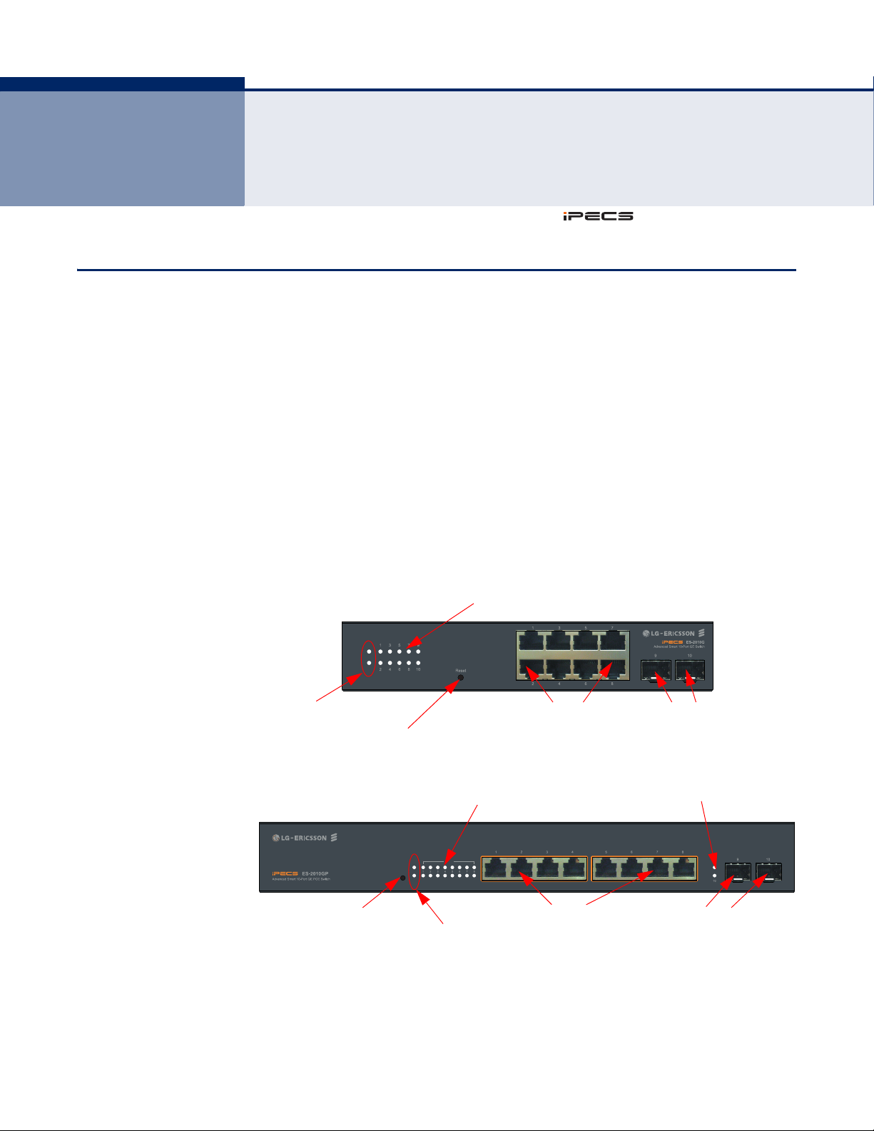
OVERVIEW
The ES-2010G and ES-2010GP are Gigabit Ethernet Layer 2 switches with
8 10/100/1000BASE-T ports, and 2 Small Form Factor Pluggable (SFP)
transceiver slots, (see Figure 1 on page 16, Ports 9-10). The ES-2010GP
also provides PoE power to connected devices.
The switches also include an SNMP-based management agent, which
provides in-band access for managing the switch.
Both switches provide a broad range of powerful features for Layer 2
switching, delivering reliability and consistent performance for your
network traffic. They bring order to poorly performing networks by
segregating them into separate broadcast domains with IEEE 802.1Q
compliant VLANs, and empowers multimedia applications with multicast
switching and CoS services.
Figure 1: Front Panels - ES-2010G / ES-2010GP
– 16 –
ES-2010G / ES-2010GP
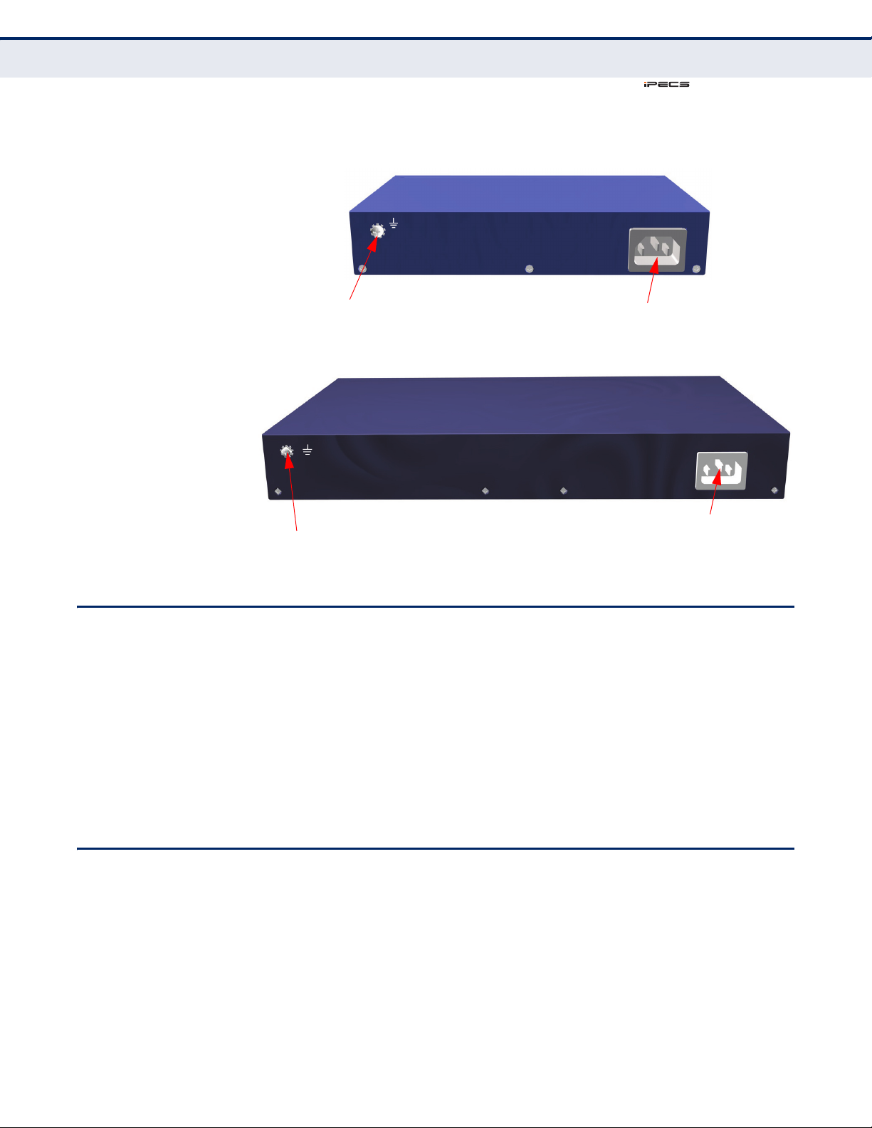
Figure 2: Rear Panels
AC 100-240V, 50~60Hz, 1.7AAC 100-240V, 50~60Hz, 1.7A
Grounding Point
Power Inlet
Grounding Point
Power Inlet
ES-2010G
ES-2010GP
C
HAPTER
Switch Architecture
AC 100-240V~, 50-60Hz, 0.5A
1
| Introduction
SWITCH ARCHITECTURE
These switches employ a wire-speed, non-blocking switching fabric. This
permits simultaneous wire-speed transport of multiple packets at low
latency on all ports. The switch also features full-duplex capability on all
ports, which effectively doubles the bandwidth of each connection.
The switches use store-and-forward switching to ensure maximum data
integrity. With store-and-forward switching, the entire packet must be
received into a buffer and checked for validity before being forwarded. This
prevents errors from being propagated throughout the network.
NETWORK MANAGEMENT OPTIONS
With a comprehensive array of LEDs, the switch provides “At-a-glance”
monitoring of network and port status. The switch can be managed over
the network with a web browser.
For a detailed description of the management features, refer to the User
Manual.
– 17 –

C
ES-2010G / ES-2010GP
HAPTER
Power-over-Ethernet
1
| Introduction
POWER-OVER-ETHERNET
All eight ports (1~8) of the ES-2010GP switch support the IEEE 802.3at
standard that enables DC power to be supplied to attached devices using
wires in the connecting Ethernet cable. The total PoE power delivered by all
ports cannot exceed the 75 W power budget.
Any PoE-compliant device attached to a port can directly draw power from
the switch over the Ethernet cable without requiring its own separate
power source. This capability gives network administrators centralized
power control for devices such as IP phones and wireless access points,
which translates into greater network availability.
For each attached PoE-compliant device, the switch automatically senses
the load and dynamically supplies the required power. The switch delivers
power to a device using the wire pairs in UTP or STP cable. Any RJ-45 port
on the switch can provide up to 34.2 W of power, but only two ports can
deliver 34.2 W simultaneously to attached devices without exceeding the
switch power budget.
DESCRIPTION OF HARDWARE
10/100/1000BASE-T
PORTS
SFP TRANSCEIVER
SLOTS
The switches contain 8 RJ-45 ports that operate at 10 Mbps or 100 Mbps,
half or full duplex, and 1000 Mbps full duplex. Because all ports on these
switches support automatic MDI/MDI-X operation, you can use straightthrough cables for all network connections to PCs or servers, or to other
switches or hubs. (See “1000BASE-T Pin Assignments” on page 47.)
Each of these ports supports auto-negotiation, so the optimum
transmission mode (half or full duplex), and data rate (10, 100, or 1000
Mbps) can be selected automatically. If a device connected to one of these
ports does not support auto-negotiation, the communication mode of that
port can be configured manually.
Each port also supports IEEE 802.3x auto-negotiation of flow control, so
the switch can automatically prevent port buffers from becoming
saturated.
The Small Form Factor Pluggable (SFP) transceiver slots are independent
ports.
The following table shows a list of transceiver types which have been
tested with the switch. For an updated list of vendors supplying these
transceivers, contact your local dealer. For information on the
recommended standards for fiber optic cabling, see “Fiber Standards” on
page 48.
– 18 –
 Loading...