


LG Electronics USA LGSWFAC73 User Manual

51
INSTALLING CALIBRATION
SOFTWARE
- How to install ......................................................... 68
- How to delete ........................................................ 68
............................ 68
CONNECTION TYPES ............ 69
X-ray Generator and Detector
Connection of Detector - PC
Mode of connecting Network
- Trigger Cable Instruction ................................. 70
- Detector and PC(Wired mode) .................... 72
- Detector and PC(Wireless mode) ...............75
CALIBRATION SOFTWARE ... 77
- Calibration Software .......................................... 77
Settings
Calibration
User BPM
Validation
Exposure Index
- Image Functions ................................................... 82
- Log................................................................................84
USAGE.................................... 85
- Launching the Program .................................... 85
- Checking IP Address and Ping Test ........... 86
- Checking Save Location ...................................87
- Apply ........................................................................... 88
- Checking and Changing Detector Settings .
89
- Checking and Changing Calibration
Software Settings................................................90
- Calibration ................................................................ 92
- User BPM ................................................................. 94
- Validation .................................................................. 96
- EI (Exposure Index) ............................................. 98
- Exit ............................................................................ 100
- About ....................................................................... 101
- General PopUp .................................................. 102
SERVICE MANUAL ..............104
- Detector Wired IP Address Setting ........ 104
- Wireless AP configuration ........................... 106
- Detector Firmware Update .........................108
- Storage of installation date ........................ 110
- Power Options Setting ..................................111
- Web monitoring ................................................. 112
Internal Information
Web monitoring
MAINTENANCE ................... 114
- Cleaning .................................................................. 114
- Inspection .............................................................. 114
TROUBLESHOOTING ........... 115
SOLUTION FOR FIREWALL
BLOCK
..................................116
SUPPLEMENT. WIRELESS AP
SET UP INSTRUCTION
(MODEL : Cisco Linksys
EA9200)
...............................118
ENGLISH
52
SAFETY INFORMATION
ENGLISH
Preparation
• Be sure to connect the cables to the proper connectors. Otherwise, the detector may malfunction or may be
damaged.
• The power supply provided by LG is designed for the detector from LG. Please contact supply, if any other type of
power supply is needed to be used.
• Be sure to fully charge the battery before use. Charge the battery on the day of examination or on the previous day.
• Battery slowly discharges even when not in use. The battery may have expired if it discharges immediately after being
fully charged. You can purchase an optional battery to replace an exhausted one.
• The battery charger provided by LG is designed for the dedicated battery.
• When the detector will not be used for some time, remove the battery.
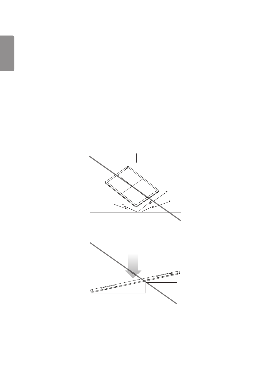
Handling
• Handle the detector carefully, as it may become damaged if it is hit, dropped, or receives a strong jolt.
• Be sure to use the detector on a flat place so it will not bend. Otherwise, the detector may be damaged.
• Be sure to check the detector daily and confirm that it works properly. Sudden heating of the room in cold areas
will cause condensation to form on the detector. In this case, wait until condensation disappears before performing
exposure. If the detector is used with condensation formed on it, problems may occur in the quality of the detector.
When an air-conditioner is going to be used, be sure to raise/lower the temperature gradually so that a difference
in temperature in the room and in the detector does not occur, to prevent forming of condensation. Follow the
53
recommended proper Room temp.
• Do not use the detector near devices generating a strong magnetic field. Doing so may produce image noise or
artifacts.
• Keep the connectors free from being in contact with the patient.
• Connectors are intended to be connected to an external device and must follow IEC standards.
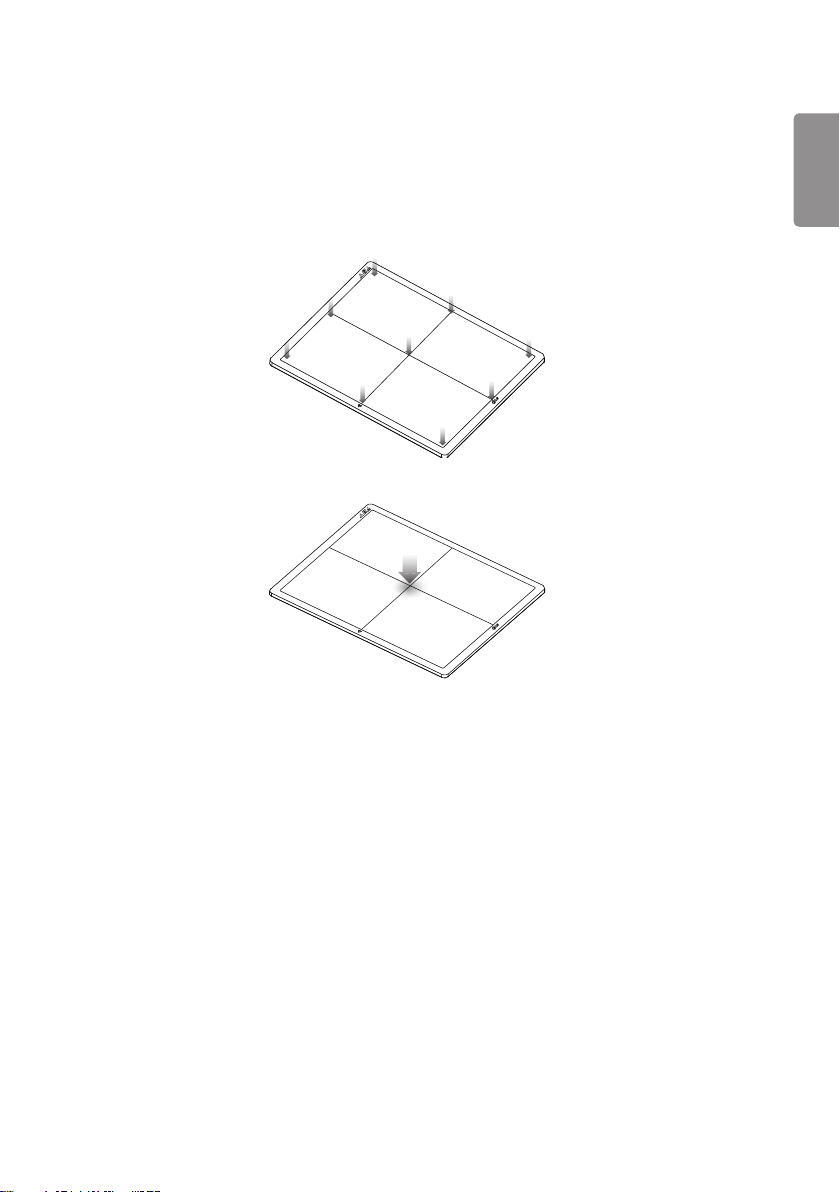
• Do not apply excessive weight to the detector. Otherwise, the detector may be damaged.
Overall Pressure: 150kg (330.6lb) over the whole area of detector window.
ENGLISH
Partial Pressure: 100kg (220.4lb) on an area 40mm (1.5 inch) in diameter
Disinfection and Cleaning
• Do not spray disinfectants or detergents on the detector.
• When cleaning the detector, be sure to turn off the power, and unplug the power cable from the AC outlet.
• Do not use any flammable chemicals such as thinner, benzene for cleaning. Otherwise, fire or electric shock may
result.
• Wear waterproof gloves to protect your hands from direct contact with disinfectants or detergents.General
Description.

54
Overview
ENGLISH
14HJ701D is wireless Flat Panel Digital X-ray Detector that can generate images of any part of the body, and designed
for a faster approach to digital radiography systems.
This model utilize a combination a amorphous silicon TFT glass and high performance scintillator, along with a pixel
pitch 127um and 3.9lp/mm of resolution, assure sharp and high contrast image quality.
14HJ701D is X-ray imaging acquisition device that is based on flat-panel. This device should be integrated with an
operating PC and a X-ray generator. It can do to utilize as digitalizing X-ray images and transfer for radiography
diagnostic. Data transmission between detector and PC is possible by wire (cable) and wireless (WIFI).
Product Component
• Detector: 14HJ701D
• Control Box : LG Control Box
- AC power cord for Control Box
• Battery Charger : LG Battery Charger
- 2 Battery packs
- AC Power adapter for Charger : 65 W
- AC Power cord for AC Power adapter
• Main Cable
- Detector and Control Box link cable (Supply DC power, Ehternet data, control signals of X-ray generator)
- Trigger Cable (X-ray generator to Control Box, transmit control signal between detector and X-ray generator)
- LAN cable (Control Box to PC, exchanges Ethernet data between PC and detector)
• CD: User’s manual, Calibration Software
• User's manual(book type), Inspection Report
55
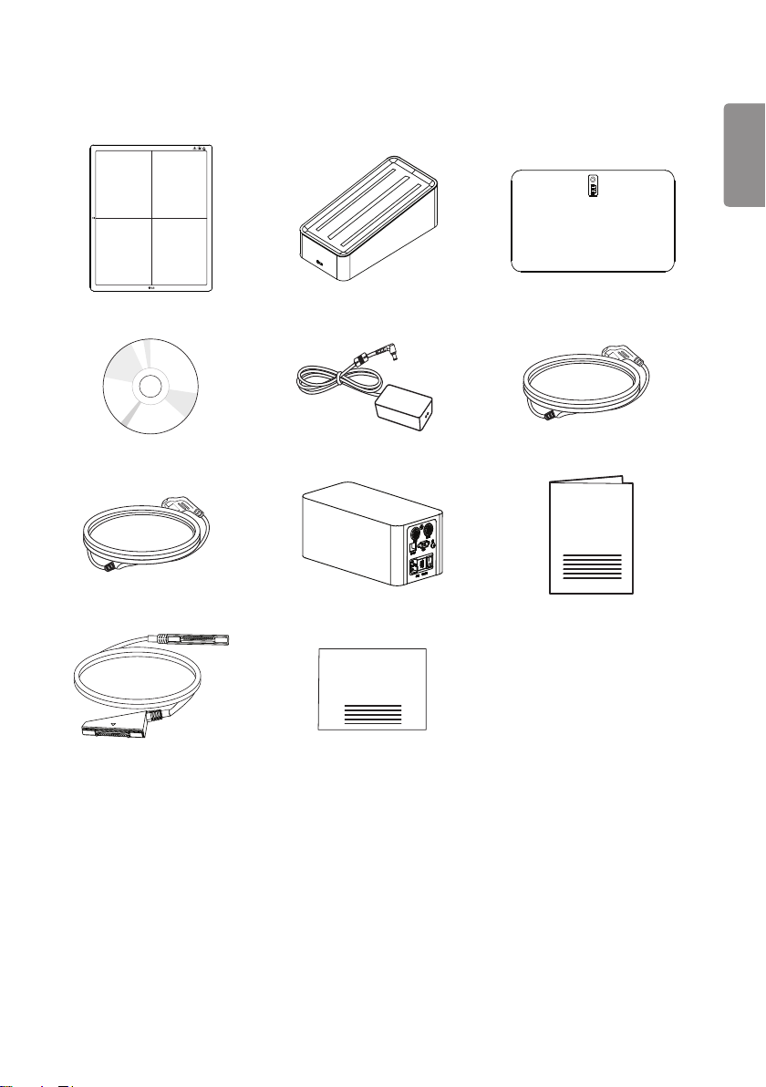
Basic Accessories
Detector 1 EA Charger 1 EA Battery 2 EA
Installation CD 1 EA AC Power adapter 1 EA AC Power cord for Control Box 1EA
AC Power cord for AC Power adapter Control Box 1EA Manual 1 EA
ENGLISH
Main cable 1EA Inspection Report 1EA
56
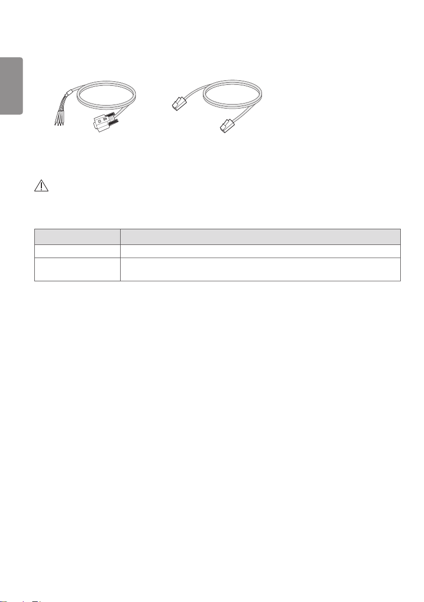
Optional Accessories
ENGLISH
Trigger Cable 1EA LAN cable 1EA
• Optional accessories can not be included in accordance with production suffix.
CAUTION
• Need to use the authorized components about the below accessories. Unauthorized components may be cause of the
damage and malfunction of the product.
Component Standard
LAN CABLE More than CAT5E Standard
Power Cord US – Approved Medical grade regulation
Others – Approved country safety regulation
The AC/DC adaptors and etc. except the upper components need to be used only supplied by manufacturer.
57
PART NAME AND FUNCTION
Detector
FRONT
ENGLISH
58
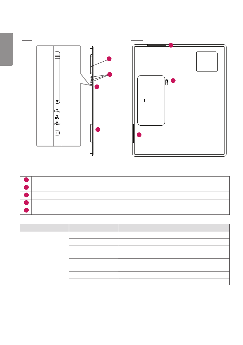
SIDE BACK
ENGLISH
5
4
3
1
2
1
1
Wireless Antenna
2
Battery Unlock Lever: Unlock lever to remove battery
3
Power Button: Power on/off switch (On : press over 1 sec, Off : press over 5 sec)
4
LED Indicator: Indicating detector’s status
5
Connection to main cable
LED LED Color Status
Battery Green Battery is more than 30% charged.
Orange Battery charging stauts is 10 ~ 30%.
Orange Blinking Battery is less than 10 % charged.
Link Green Ethernet/WIFI connection
Off Ethernet/WIFI no connection
Power Green Power On
Green Blinking Sleep mode
Off Power Off
If there is no communication during "Auto Sleep/Auto Power off" time, Detector will go to Sleep mode/Power off.
This function only works when Detector is not connected with “Detector and Control Box link cable”.
If the Detector receives the communication message during Sleep mode, The Detector will wake up.
1
User can set the Sleep/Power off times using the Calibration Software.
59
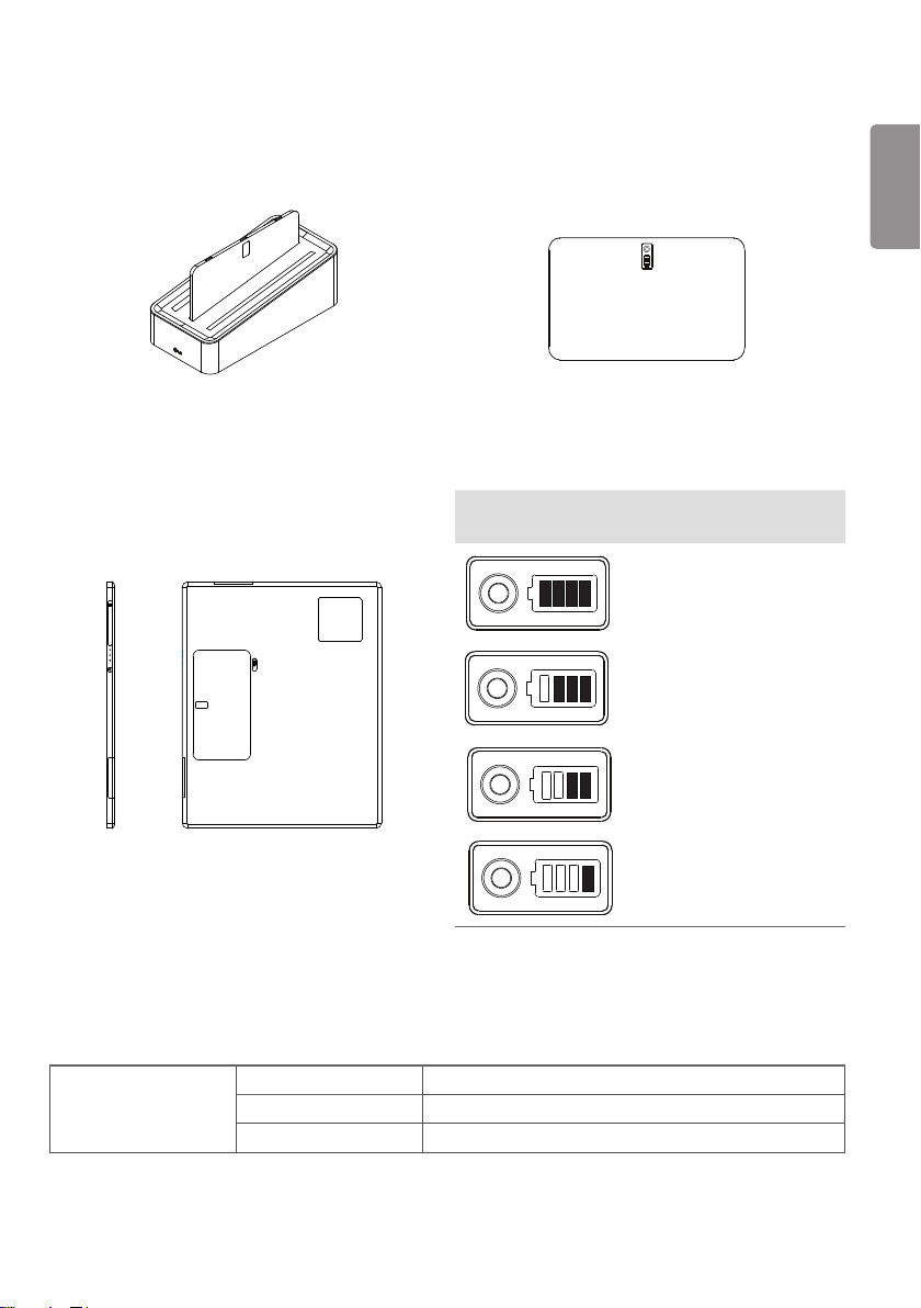
Battery and Charger
1 Battery: Li-ion polymer battery (Charging time - Typ. 4 Hrs)
• Battery pack itself shows the remaining battery percentage.
Battery Remain
Indicator
ENGLISH
Battery Level
75 ~ 100%
50 ~ 75%
2 Battery charger: 3 ports cradle type
3 LED Indicator: Following LEDs are located to each battery - 3 batteries.
LED Green Completion of charging
Orange On charging
Orange Blinking Error (Connection error, etc)
25 ~ 50%
0 ~ 25%
60
255
125
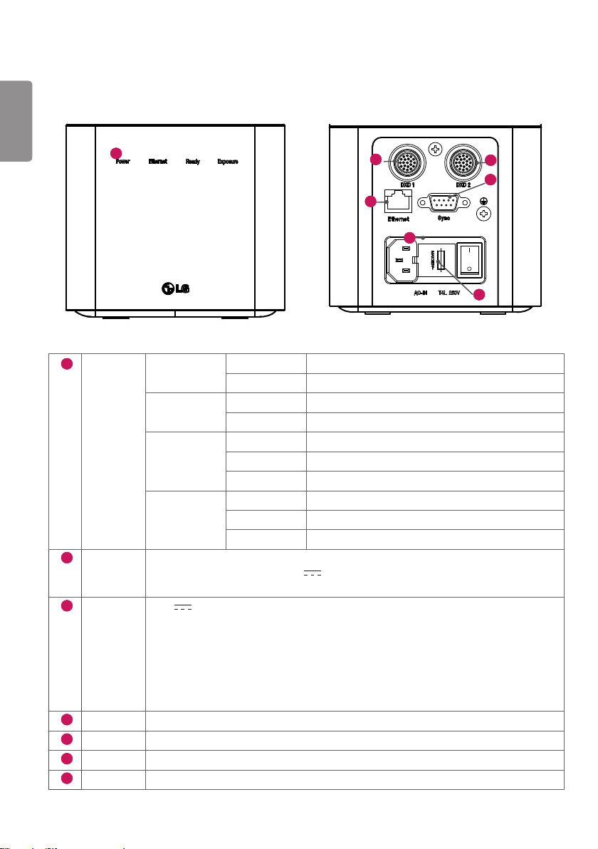
Control Box
ENGLISH
1
1
LED POWER Green Power normal operation
Off Power off (AC power cord no connection or Power error.)
Ethernet Green Ethernet normal operation
Off Ethernet disconnected.
Ready Green Ready signal from X-ray generator is active.
Off Ready signal from X-ray generator is inactive.
Orange blink Error
Exposure Orange Exposure signal from X-ray generator is active.
Off Exposure signal from X-ray generator is inactive.
Orange blink Error
2
DXD 1 Connecting the Control Box and the detector A.
This connector supply power (24 V 2.1 A) to the detector, transmits X-ray
synchronization signals and Ethernet image data.
3
4
5
6
7
DXD 2 24 V 2.1 A, Trigger signals, Ethernet data for Detector B
Control Box supports 2 Detector connection.
Usage is, one is for bucky stand, the other is for table(bed).
Generally, X-ray room of hospital installs 2 detectors, bucky stand and table type, it's for more
convinient and efficient working environment.
These 2 detectors are not operated simutaniously, control box selects the operating detector
by AWS command.
AC-IN Connects AC power cord
Ethernet Ethernet port to transmit image/command between the detector and PC.
Sync This is to synchronize the detector and X-ray generator.
Fuse T4L 250V
2
5
4
3
6
7
61
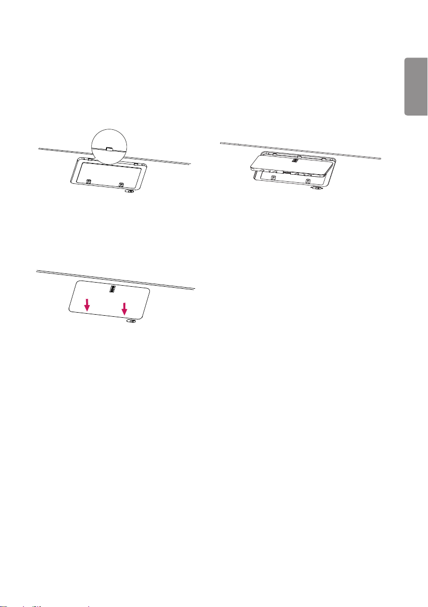
BATTERY INSTALLATION
1 Check the battery mounting hole direction. 2 Insert into the hole on the side with the indicator.
3 Press the opposite side to secure the battery
indicator.
ENGLISH

62
SPECIFICATION OF EACH PART
ENGLISH
The product specifications are subject to change without prior notice for product improvements.
“ ~ ” refers to alternating current (AC), “
” refers to direct current (DC).
Detector
Item Specification Units
Model 14HJ701D
Sensor type Amorphous Silicon with TFT
Scintillator Type CsI:TI
Total Pixel Matrix 3328 x 2816 Pixels
Total Pixel Area 422.655 (16.63) x 357.632 (14.08) mm (inch)
Pixel Pitch 127 um
Effective Pixel Matrix 3323 x 2751 pixels
A/D Conversion 16 bits
Data Transfer 802.11 a/g/n/ac Wireless LAN, typ. 200Mbps with 802.11ac
Gigabit Ethernet typ. 500Mbps
Preview time 2 sec
Energy range 40 ~ 150 kVp
MTF Typ. 85%, min. 70% at 0.5 lp/mm %
DQE Typ. 63%, min. 50% at 0.1 lp/mm %
Defective lines Less than 20 Lines
Defective pixels Less than 9630 Pixels
Dimension 384.0 x 459.5 x 15.0 (15.1 x 18.0 x 0.5) mm (inch)
Weight Typ. 2.95 (6.5) kg (lb)
Window material Carbon Fiber
Trigger mode Manual Mode
Auto Mode (Auto Exposure Detection)
Power consumption Typ. 26 (Charging & Operating)
Typ. 16 (Operating only – no charging)
Typ. 7 (Standby only – no charging)
Wireless Standard:
802.11 a/g/n/ac compliance
Peak mode: 866 Mbps
Frequency: 2.4 GHz / 5 GHz
Bandwidth: 20 MHz / 40 MHz / 80 MHz
MIMO: 2X2
Rating 24 V
Applied part Type : BF Type, Location : Front of Detector (only for effective area)
2.1 A, 7.5 V 3850 mAh (Battary: LBQ7222L)
W
63
NOTE
• Maximum wireless signal rate derived from IEEE standard specifications. Actual data throughput will vary. Network
conditions and environmental factors, including volume of network traffic, building materials and construction, and
network overhead, lower actual data throughput rate.
• Recommended Maximum operable distance: 2 m (From the Access Point)
• Wireless antennas: The module adopts the latest 802.11ac technology. The transmitter of the module is powered by
host equipment (Detector). The antennas are 2 printed-dipole antennas.
• Wireless module: 802.11 a/b/g/n/ac USB2.0 module is implemented. It supports 2T2R (2 transmit 2 receive) MIMO
technology, which delivers throughput up to 300 Mbps.
Battery
Item Specification Units
Model LBQ7222L
Rating 7.5 V, 3850 mAh, 30 Wh
Size 204.1 x 10.5 x 7.8 (8.0 x 0.4 x 0.3) mm (inch)
Weight Typ. 240 (0.5) g (ib)
Output Norminal voltage 7.5 VDC
Cycle time Max. 800 Cycles
Operation Temp 10 - 35
Charging time Typ. 4 Hours
Capacity Typ. 4000 mAh
Battery performance 1400 shots acquired for 3.2 hours
(cycle time 8s , without sleep , with Full charged battery)
℃
Images
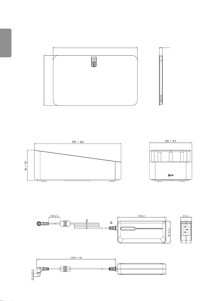
Battery Charger
ENGLISH
Item Specification Units
Model LG Battery Charger
Size 125 x 255.0 x 90.0 (4.9 x 10.0 x 3.5) mm (inch)
Weight Typ. 900 (1.9) g (ib)
Input 19 V
Output Norminal voltage 8.7 VDC
3.42 A
Battery Charger Adapter
Item Spec Units
Model DA-65J19
Manufacturer Asian Power Devices Inc. (APD)
Size 134.0 x 59.8 x 31 (5.2 x 2.3 x 1.2) mm (inch)
Weight Typ. 335 g (ib)
Input 100-240 V ~, 50-60 Hz, 1.5-0.7 A
Output 19 V
Class I
Cable length 1500 (59) mm (inch)
3.42 A
64
Control Box
ENGLISH
mm (inch) Desc. Specification Units
Model LG Control Box LG Control Box
Size 125.0 x 255.0 x 109.8 (4.9 x 10.0 x 4.3) mm (inch)
Weight Typ. 1.3 (2.86) kg (Ib)
Input AC Power 100-240 V ~, 50/60 Hz, 1.4-0.7 A
AC Inlet Fuse 1 T4L 250V
AC Inlet Fuse 2 T4L 250V
Power Fuse 1 (F101) T 3.15AH 250V
Power Fuse 2 (F102) T 3.15AH 250V
Output DXD 1 24 V
DXD 2 24 V
Ethernet Transmission image/command between the detector and PC
Sync Transmission control signals between the detector and X-ray
2.1 A, Trigger signals, Ethernet data for Detector A
2.1 A, Trigger signals, Ethernet data for Detector B
Control Box supports 2 Detector connection.
Usage is, one is for bucky stand, the other is for table(bed).
Generally, X-ray room of hospital installs 2 detectors, bucky
stand and table type, it's for more convinient and efficient
working environment.
These 2 detectors are not operated simutaniously, control box
selects the operating detector by AWS command.
generator
Cables
Item Length Unit Qty
Main cable 1 (39.3) m (inch) 1
LAN cable (optional) 10 (393.7) m (inch) 1
Power cord (110 V or 220 V) 1.5 (59.0) m (inch) 2
Trigger cable (Optional) 15 (590.5) m (inch) 1
65
255 / 10.0
109.8 / 4.3
125 / 4.9
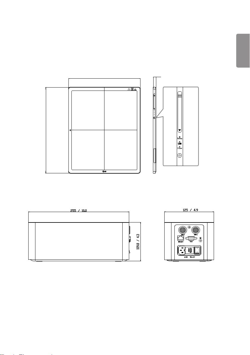
DIMENSION (UNIT: mm/inch)
Detector
384 / 15.1
459.5 / 18.0
Control Box
ENGLISH
15 / 0.5
66
204.6 / 8.0
110.5 / 4.3
7.8 / 0.3
Ⰼ
ম
ম
ম
Ⰼ
ম
Battery
ENGLISH
Battery Charger
90 / 3.5
Battery Charger Adapter
255 / 10.0
125 / 4.9
67
ENVIRONMENTAL REQUIREMENT
PC system requirement
PC Specification
CPU intel i5
Memory 4 GB
Disk capacity At least 10 GB, 500 GB recommended
Network card dual ethernet 100/1000 bps
OS Windows 7/8.1/10(32bit, 64bit)
Monitor Min. Resolution 1280x720
AP Cisco model is recommended(ex : Linksys EA9200)
etc
Environmental Requirements
Item Min. Typ Max. (%) Units
Temperature (Storage) -20 60
Temperature (Operation) 10 35
Humidity (Storage) 85 Non-condensing, Relative
Humidity (Operation) 80
Pressure (Storage) 50 106 kPa
Pressure (Operation) 70 106 kPa
℃
℃
Humidity
ENGLISH

68
INSTALLING CALIBRATION SOFTWARE
ENGLISH
How to install
Run the calibration software installation file. Once the installation file has been executed, follow the installation
instructions on the screen.
How to delete
You can delete the Calibration Software in the following ways:
Deleting from the Control Panel
1 Select Control Panel from the Start menu.
2 Select Programs and Features in Control Panel.
3 Select the LG DXD Calibration on the lists.
4 When the program installation and deletion screen appears on the screen, select the Delete button.
5 Follow the deletion instructions on the screen and click the Next button to proceed.
Deleting with the installation file
1 Run the calibration software installation file, then follow the deletion instructions on the screen.
NOTE
• When using the installation file to delete the program, the installation file must be the same version as the current
software.
69
CONNECTION TYPES
X-ray Generator and Detector
Select Trigger Mode in accordance with the acquisition method.
- Auto Mode : Detector detects the image obtained after the X-ray
- Manaul Mode : Detector acquires image by pressing generator exposure switch
Connection of Detector - PC
The connection mode used between the detector and PC.
- Wired Mode: Uses the Control Box to connect the detector to a PC.
- Wireless Mode: Uses a wireless AP to connect the detector to a PC.
Mode of connecting Network
Wired or wireless modes are set automatically depending on whether or not the main cable is connected when the
detector is turned on.
1 If the main cable is connected when the power is turned on: Wired mode
2 If the main cable is not connected when the power is turned on: Wireless mode
3 If the cable is disconnected while in wired mode: Switches to wireless mode
4 If the cable is connected while in wireless mode: Maintains wireless mode (charging)
Mode Generator - Detector Detector - PC
Case 1 Auto Mode Wired Mode
Case 2 Auto Mode Wireless Mode
Case 3 Manual Mode Wired Mode
Case 4 Manual Mode Wireless Mode
ENGLISH
70
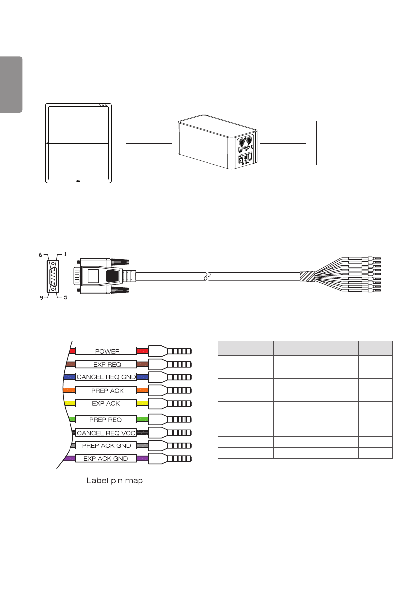
Trigger Cable Instruction
ENGLISH
• Connects a Trigger cable to Port A of the Control Box when there is X-ray generator interface.
Generator
No. COLOR Description
1 RED POWER Use
2 BRN EXP REQ Use
3 BLU CANCEL REQ GND NC
4 ORG PREP ACK NC
5 YEL EXP ACK Use
6 GRN PREP REQ Use
7 BOK CANCEL REQ VCC NC
8 GRY PREP ACK GND NC
9 VIO EXP ACK GND Use

71
ENGLISH
-
EXP_REQ
EXP_ACK
<Assembly Diagram>
<Timing Chart>
72
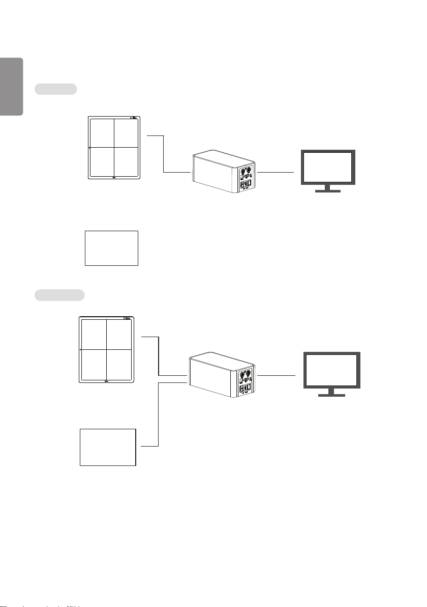
Detector and PC(Wired mode)
ENGLISH
Auto Mode
Detector
Generator
Manual Mode
Main Cable
PC
LAN cable
Detector
Generator
Main Cable
PC
LAN cable
Trigger Cable