How it Works
Log In / Sign Up
Buy Points
How it Works
FAQ
Contact Us
Questions and Suggestions
Users
LG Electronics USA
Loading...
E
E2422PYB
E2441VX
E2442VA
E2742VA
2
E410F
5
E410G
2
E410J
2
E435G
E440
E440G
E440J
E450F
E450G
E450J
E455F
E465G
E510F
E610
E610V
E906
E972
E989
2
EAX5296
EAX57538201
2
EAX6069
F
F23GDA07
2
F31GDA
3
G
G4010
GD910
GM210
2
GT350
2
GT500
GU290F
GW300
2
GW382F
GW525
GW525F
GW525G
H
H443
H525N
H790
H791
HBM-905
HBS750
2
HBS760
HBS850
HBSW120
HBS-XL7
2
HX300GJE
I
IPS226TX
IPS234TA
IPS234VA
2
K
K373
KF700
KF757
KM900
KM900QA
2
KS1301
2
KS500Q
KT610
KT770
2
KT770F
L
L01C
L01D
L02A
L02C
L04C
L05A
2
L05D
L06A
3
L07C
L1400
L1742HT
L1753HS
L1755TT
L1760TQ
L1770HN
L1780UN
L17LB
L18LA
L190N
L1942HEU
L1953HS
L1960TQ
L1980UN
L21G
2
L226WTQS
L30LP
L601I
L602I
L705I
LACFS
LACT10-R
LAEF10-R
LAFP10-R
3
LGL22
4
LGSWFAC73
2
LH2065H
LHC5200WI
LK460
Loading...
Loading...
Nothing found
IPS234TA
User Manual
28 pgs
1.43 Mb
0
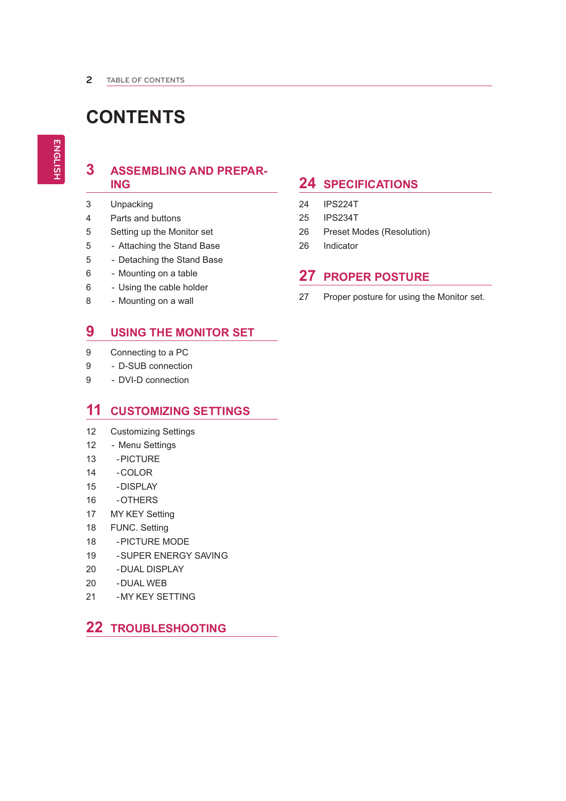
Table of contents
Loading...
LG Electronics USA IPS234TA User Manual
...
LG Electronics USA User Manual
Download
Specifications and Main Features
Frequently Asked Questions
User Manual
Download
Page 1
Page 2
Page 3
Page 4
Page 5
Page 6
Page 7
Page 8
Page 9
Page 10
Page 11
Page 12
Page 13
Page 14
Page 15
Page 16
Page 17
Page 18
Page 19
Page 20
Page 21
Page 22
Page 23
Page 24
Page 25
Page 26
Page 27
Page 28
Loading...
+
hidden pages
Unhide
You need points to download manuals.
1 point = 1 manual.
You can buy points or you can get point for every manual you upload.
Buy points
Upload your manuals