

Page 1

PREPARATION
21
DESKTOP PEDESTAL INSTALLATION
KENSINGTON SECURITY SYSTEM
■
This feature is not available for all models.
- The TV is equipped with a Kensington Security System connector on
the back panel. Connect the Kensington Security System cable as
shown below.
- For the detailed installation and use of the Kensington Security
System, refer to the user’s guide provided with the Kensington
Security System.
For further information, contact
http://www.kensington.com
,
the internet homepage of the Kensington company. Kensington sells
security systems for expensive electronic equipment such as notebook PCs and LCD projectors.
NOTE: The Kensington Security System is an optional accessory.
SWIVEL STAND
After installing the TV, you can adjust the TV set manually to the left or right direction by 20 degrees to suit
your viewing position.
For proper ventilation, allow a clearance of 4 inches on all four sides from the wall.
■
Image shown may differ from your TV.
4 inches
G
Ensure adequate ventilation by following the clearance recommendations.
G
Do not mount near or above any type of heat source.
CAUTION
4 inches
4 inches
4 inches
Page 2
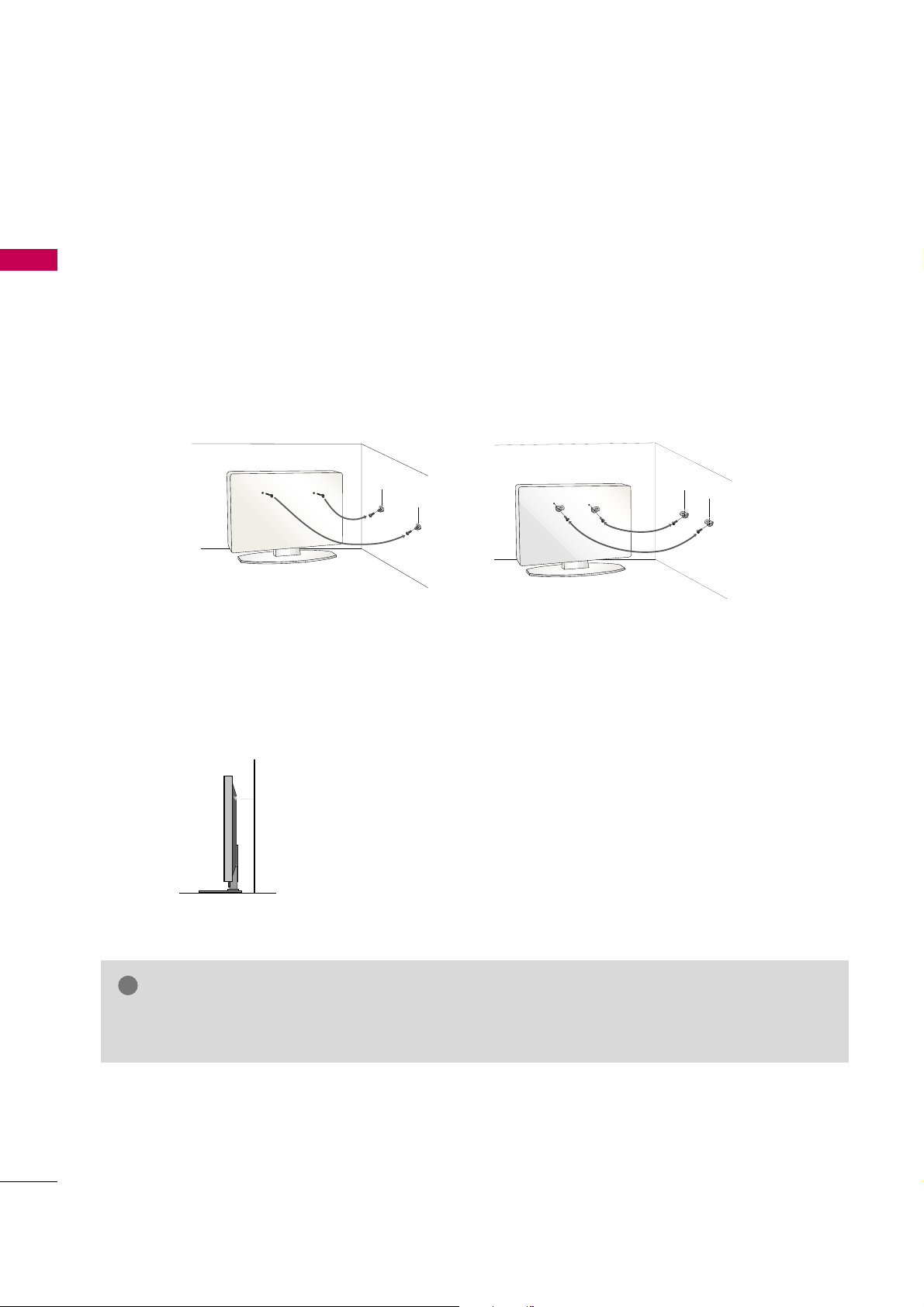
We recommend that you set up the TV close to a wall so it cannot fall over if pushed backwards.
Additionally, we recommend that the TV be attached to a wall so it cannot be pulled in a forward direction,
potentially causing injury or damaging the product.
Caution: Please make sure that children don’t climb on or hang from the TV.
■
Insert the eye-bolts (or TV brackets and bolts) to tighten the product to the wall as shown in the picture.
*If your product has the bolts in the eye-bolts position before inserting the eye-bolts, loosen the bolts.
* Insert the eye-bolts or TV brackets/bolts and tighten them securely in the upper holes.
Secure the wall brackets with the bolts (sold separately) to the wall. Match the height of the bracket that is
mounted on the wall to the holes in the product.
Ensure the eye-bolts or brackets are tightened securely.
■
Use a sturdy rope (sold separately) to tie the product. It is safer to tie
the rope so it becomes horizontal between the wall and the product.
■
You should purchase necessary components to prevent the TV from tipping over (when not using a wall mount).
■
Image shown may differ from your TV.
G
Use a platform or cabinet strong enough and large enough to support the size and weight of the TV.
G
To use the TV safely make sure that the height of the bracket on the wall and the one on the TV are the same.
NOTE
!
PREPARATION
22
SECURING THE TV TO THE WALL TO PREVENT FALLING
WHEN THE TV IS USED ON A STAND
PREPARATION
Page 3

PREPARATION
23
ANTENNA OR CABLE CONNECTION
■
To prevent damage do not connect to the power outlet until all connections are made between the devices.
■
Image shown may differ from your product.
1. Antenna (Analog or Digital)
Wall Antenna Socket or Outdoor Antenna without a Cable Box
Connections.
For optimum picture quality, adjust antenna direction if needed.
2. Cable
Wall
Antenna
Socket
Outdoor
Antenna
(VHF, UHF)
Cable TV
Wall Jack
Multi-family Dwellings/Apartments
(Connect to wall antenna socket)
RF Coaxial Wire (75 ohm)
RF Coaxial Wire (75 ohm)
Single-family Dwellings /Houses
(Connect to wall jack for outdoor antenna)
Be careful not to bend the copper wire
when connecting the antenna.
Copper Wire
■
To improve the picture quality in a poor signal area, please purchase a signal amplifier and install properly.
■
If the antenna needs to be split for two TV’s, install a 2-Way Signal Splitter.
■
If the antenna is not installed properly, contact your dealer for assistance.
■
Refer to
http:/ /Anten n a W e b . o r g
for more information about antennas and Digital TV.
ANTENNA/
CABLE IN
ANTENNA/
CABLE IN
1
2
1
2
COMPONENT IN
AV IN
LYPBPRR
VIDEO
AUDIO
L(MONO)
R
213
/DVI IN
RGB IN (PC)
AUDIO IN
(RGB/DVI)
SERVICE ONLY
OPTICAL
DIGITAL
AUDIO OUT
ANTENNA/
CABLE IN
RS-232C IN
(SERVICE ONLY)
OFFON
AC IN
VIDEO
AUDIO
Page 4

EXTERNAL EQUIPMENT SETUP
24
EXTERNAL EQUIPMENT SETUP
HD RECEIVER SETUP
This Media Box can receive digital over-the-air/digital cable signals without an external digital set-top box.
However, if you do receive digital signals from a digital set-top box or other digital external device.
Component Connection
1. How to connect
Connect the video outputs (Y, PB, PR
)
of the digital set-
top box to the
COMPONENT I N VIDEO 1
or
2
jacks on the Media Box. Match the jack colors (Y =
green, P
B = blue, and PR = red).
Connect the audio output of the digital set-top box to
the
COMPONENT IN AU D I O 1
or 2jacks on the
Media Box.
2
1
2. How to use
■
Turn on the digital set-top box.
(
Refer to the owner’s manual for the digital set-top box operation.
)
■
Select the
Component1
or
Component2
input source
using the
INPU T
button on the remote control.
■
To prevent the equipment damage, never plug in any power cords until you have finished connecting all equipment.
■
Image shown may differ from your product.
Y, CB/PB, CR/P
R
Supported Resolutions
Horizontal Vertical
Frequency(KHz)Frequency(Hz
)
15.73 59.94
15.73 60.00
31.47 59.94
31.50 60.00
44.96 59.94
45.00 60.00
33.72 59.94
33.75 60.00
26.97 23.97
27.00 24.00
33.71 29.97
33.75 30.00
67.43 59.94
67.50 60.00
Resolution
720x480i
720x480p
1280x720p
1920x1080i
1920x1080p
Signal
480i
480p
720p
10 8 0 i
10 8 0 p
Component
Yes
Yes
Yes
Yes
Yes
HDMI
No
Yes
Yes
Yes
Yes
213
/DVI IN
RGB IN (PC)
1
2
COMPONENT IN
LYPB PR R
VIDEO
AUDIO
Y L RPBP
R
VIDEO
L(MONO)
1
2
Page 5
EXTERNAL EQUIPMENT SETUP
25
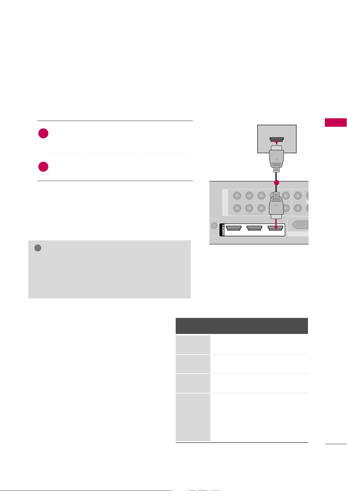
HDMI Connection
Connect the digital set-top box to
HDMI/DVI IN
1, 2, 3
, or
HDMI IN 4
jack on the Media Box or
HDMI IN 5
on the TV.
No separate audio connection is necessary.
HDMI supports both audio and video.
1. How to connect
2. How to use
■
Turn on the digital set-top box.
(
Refer to the owner’s manual for the digital set-top box.
)
■
Select the
HDMI1, HDMI2, HDMI3, HDMI4
, or
HDMI5
input source using the
INPUT
button on the remote control.
2
1
HDMI-DTV
Horizontal Vertical
Frequency(KHz)Frequency(Hz
)
31.47 59.94
31.50 60.00
44.96 59.94
45.00 60.00
33.72 59.94
33.75 60.00
26.97 23.97
27.00 24.00
33.71 29.97
33.75 30.00
67.43 59.94
67.50 60.00
Resolution
720x480p
1280x720p
1920x1080i
1920x1080p
1
2
COMPONENT IN
LYPB PR R
VIDEO
RGB IN (P
VIDEO
AUDIO
L(M
213
/DVI IN
HDMI OUTPUT
1
G
Check HDMI cable over version 1.3.
If the HDMI cables don’t support HDMI version 1.3, it can
cause flickers or no screen display. In this case use the latest cables that support HDMI version 1.3.
G
HDMI Audio Format: PCM, Dolby Digital
NOTE
!
Page 6

EXTERNAL EQUIPMENT SETUP
26
EXTERNAL EQUIPMENT SETUP
DVI to HDMI Connection
1
Connect the DVI output of the digital set-top box to
the
HDMI/DVI I N 1, 2
, or 3jack on the Media
Box.
Connect the digital set-top box audio output to the
AUDIO I N
(
RGB/DVI
)
jack on the Media Box.
1. How to connect
2. How to use
■
Turn on the digital set-top box.
(
Refer to the owner’s manual for the digital set-top
box.
)
■
Select the
HDMI1, HDMI2
, or
HDMI3
input source
using the
INPUT
button on the remote control.
2
1
1
2
1
2
COMPONENT IN
AV IN
LYPB PR R
VIDEO
AUDIO
RGB IN (PC)
VIDEO
AUDIO
L(MONO)
R
213
/DVI IN
AUDIO IN
(RGB/DVI)
L R
DVI OUTPUT
AUDIO
SE
2
1
Page 7
EXTERNAL EQUIPMENT SETUP
27
DVD SETUP
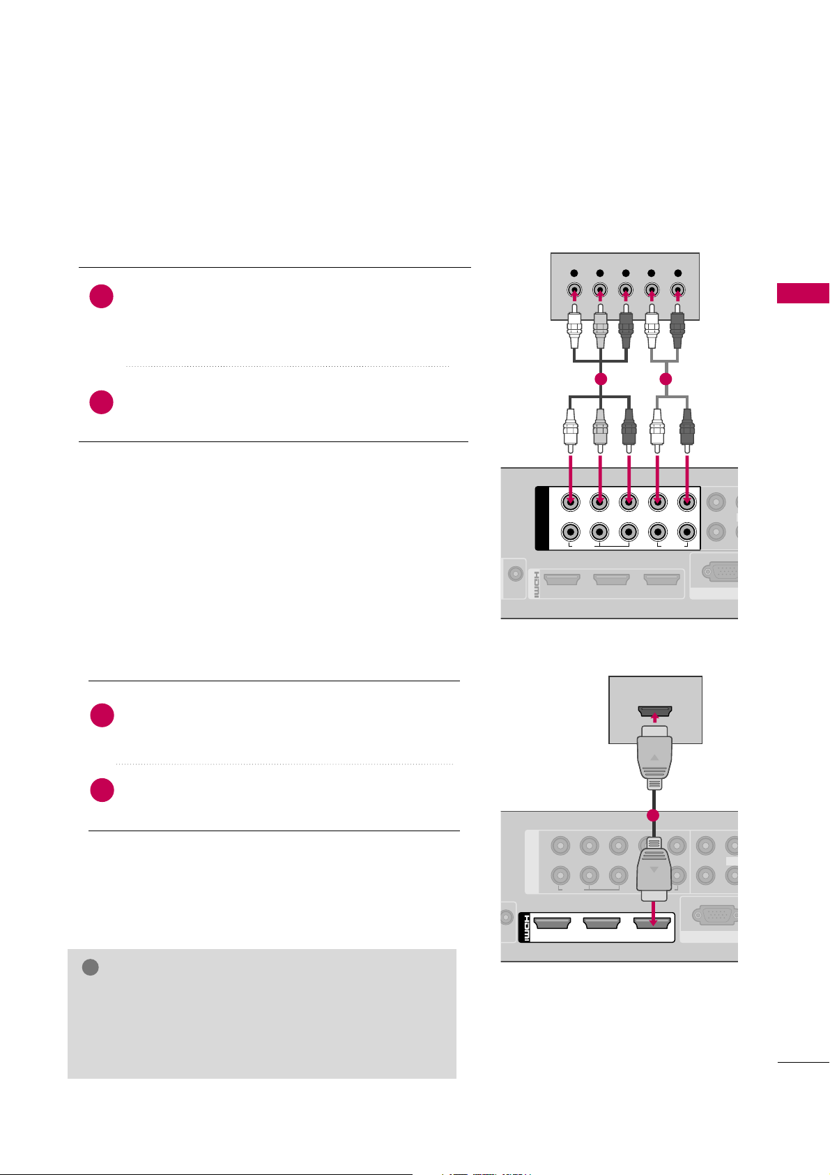
Component Connection
Connect the video outputs (Y, PB, PR
)
of the DVD to the
COMPONENT IN VI D E O 1
or 2jacks on the Media
Box. Match the jack colors (Y = green, P
B = blue, and PR =
red).
Connect the audio outputs of the DVD to the
COMPONENT IN AU D I O 1
or 2jacks on the Media
Box.
1. How to connect
2. How to use
■
Turn on the DVD player, insert a DVD.
■
Select the
Component1
or
Component2
input source
using the
INPU T
button on the remote control.
■
Refer to the DVD player's manual for operating instructions.
2
1
213
/DVI IN
RGB IN (P
1
2
COMPONENT IN
LYPB PR R
VIDEO
AUDIO
VIDEO
L
Y L RPBP
R
1 2
HDMI Connection
1
2
COMPONENT IN
LYPB PR R
VIDEO
RGB IN (PC)
VIDEO
AUDIO
L(MO
213
/DVI IN
HDMI OUTPUT
1
Connect the HDMI output of the DVD to the
HDMI/DVI IN 1, 2, 3
, or
HDMI IN 4
jack on the
Media Box or
HDMI IN 5
on the TV.
No separate audio connection is necessary.
HDMI supports both audio and video.
1. How to connect
2. How to use
■
Select the
HDMI1, HDMI2, HDMI3, HDMI4
, or
HDMI5
input source using the
INPUT
button on the remote control.
■
Refer to the DVD player's manual for operating instructions.
2
1
G
Check HDMI cable over version 1.3.
If the HDMI cables don’t support HDMI version 1.3, it can
cause flickers or no screen display. In this case use the latest cables that support HDMI version 1.3.
NOTE
!
Page 8

EXTERNAL EQUIPMENT SETUP
28
VCR SETUP
EXTERNAL EQUIPMENT SETUP
Antenna Connection
Connect the RF antenna out socket of the
VCR to the
ANTENNA/CABLE IN
sock-
et on the Media Box.
Connect the antenna cable to the RF
antenna in socket of the VCR.
1. How to connect
2. How to use
■
Set VCR output switch to 3 or 4 and then
tune Media Box to the same channel number.
■
Insert a video tape into the VCR and press
PLAY on the VCR. (Refer to the VCR owner’s
manual.
)
2
1
ANTENNA/
CABLE IN
L R
S-VIDEO VIDEO
OUTPUT
SWITCH
ANT IN
ANT OUT
AUDIO
Wall Jack
Antenna
1
2
Composite (RCA) Connection
213
/DVI IN
RGB IN (PC)
AUDIO IN
(RGB/DVI)
AV IN
VIDEO
AUDIO
L(MONO)
R
L R
S-VIDEO VIDEO
AUDIO
OUTPUT
SWITCH
ANT IN
ANT OUT
1
2
1
2
COMPONENT IN
LYPB PR R
VIDEO
AUDIO
SE
1
Connect the
AUDI O/VIDE O
jacks between Media
Box and VCR. Match the jack colors (Video = yellow,
Audio Left = white, and Audio Right = red)
1. How to connect
2. How to use
■
Insert a video tape into the VCR and press PLAY
on the VCR. (Refer to the VCR owner’s manual.
)
■
Select the
AV 1
or
AV 2
input source using the
INPU T
button on the remote control.
1
Page 9

EXTERNAL EQUIPMENT SETUP
29
OTHER A/V SOURCE SETUP
213
/DVI IN
RGB IN (PC)
AUDIO IN
(RGB/DVI)
AV IN
VIDEO
AUDIO
L(MONO)
R
L R
VIDEO
1
2
1
2
COMPONENT IN
LYPB PR R
VIDEO
AUDIO
SERVICE ONLY
Camcorder
Video Game Set
Connect the
AUDIO/VIDEO
jacks
between Media Box and external equipment. Match the jack colors
.
(
Video = yellow, Audio Left = white, and
Audio Right = red
)
1. How to connect
2. How to use
■
Select the
AV 1
or
AV 2
input source using the
INPU T
button on the remote control.
■
Operate the corresponding external equipment.
1
1
Page 10
EXTERNAL EQUIPMENT SETUP
30
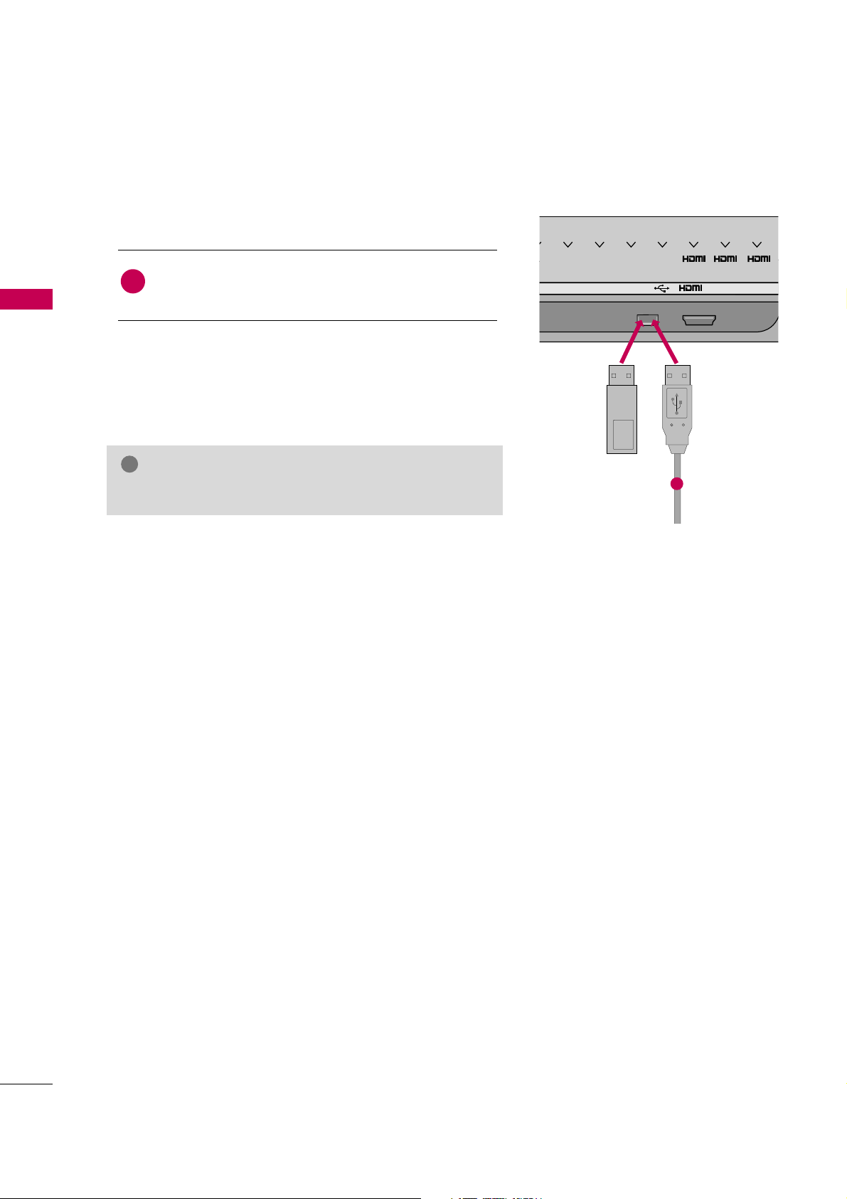
USB CONNECTION
EXTERNAL EQUIPMENT SETUP
USB IN
IN 4
1
2 3
Memory Key
Connect the USB device to the
USB I N
jack on the
Media Box.
1. How to connect
1
2. How to use
■
After connecting the
USB I N
jack, you use the USB function.
(
G
p.60
)
1
or
G
Check USB cable over version 2.0.
NOTE
!
Page 11

EXTERNAL EQUIPMENT SETUP
31
AUDIO OUT CONNECTION
1
2
AV IN
AUDIO
AUDIO IN
(RGB/DVI)
ANTE
CAB
R
OPTICAL
DIGITAL
AUDIO OUT
SERVICE ONLY
1
2
NOTE
!
G
Do not look into the optical output port. Looking at the
laser beam may damage your vision.
GG
Audio with ACP (Audio Copy Protection) function may
block digital audio output.
CAUTION
Connect one end of the optical cable to the Media Box
port of
OPTICAL DIGITAL AUDIO OUT
.
Connect the other end of the optical cable to the digital
audio input on the audio equipment.
Set the “TV Speaker - Off” in the AUDIO menu. (
G
p.94
).
See the external audio equipment instruction manual for
operation.
1. How to connect
2
3
1
Send the TV’s audio to external audio equipment via the Audio Output port.
If you want to enjoy digital broadcasting through 5.1-channel speakers, connect the OPTICAL DIGITAL
AUDIO OUT terminal on the back of Media Box to a Home Theater (or amp).
G
When connecting with external audio equipment, such as
amplifiers or speakers, you can turn the TV speakers off in
the menu. (
G
p.94
)
G
HDMI5 input source cannot be used for AUDIO OUT.
Page 12

EXTERNAL EQUIPMENT SETUP
32
PC SETUP
EXTERNAL EQUIPMENT SETUP
This TV provides Plug and Play capability, meaning that the PC adjusts automatically to the TV's settings.
VGA (D-Sub 15 pin) Connection
1
2
AV IN
LR R
VIDEO
AUDIO
1
AUDIO
L/MONO
R
RGB IN (PC)
AUDIO IN
(RGB/DVI)
RGB OUTPUT
AUDIO
SERVICE ONLY
2
1
Connect the VGA output of the PC to the
RGB IN
(
P C
)
jack on the Media Box.
Connect the PC audio output to the
AUDIO IN
(
RGB/DVI
)
jack on the Media Box.
1. How to connect
2. How to use
■
Turn on the PC and the Media Box.
■
Select the
RGB-P C
input source using the
INPU T
button
on the remote control.
2
1
DVI to HDMI Connection
1
2
1
2
COMPONENT IN
AV IN
LYPB PR R
VIDEO
AUDIO
RGB IN (PC)
VIDEO
AUDIO
L(MONO)
R
213
/DVI IN
AUDIO IN
(RGB/DVI)
AUDIO
DVI OUTPUT
1
2
Connect the DVI output of the PC to the
HDMI/DVI
IN 1, 2
, or 3jack on the Media Box.
Connect the PC audio output to the
AUDIO IN
(RGB/DVI)
jack on the Media Box.
1. How to connect
2. How to use
■
Turn on the PC and the Media Box.
■
Select the
HDMI1, HDMI2
, or
HDMI3
input source
using the
INPU T
button on the remote control.
2
1
G
Check HDMI cable over version 1.3.
If the HDMI cables don’t support HDMI version 1.3,
it can cause flickers or no screen display. In this case
use the latest cables that support HDMI version 1.3.
NOTE
!
Page 13

EXTERNAL EQUIPMENT SETUP
33
NOTES
!
Supported Display Specifications (RGB-PC, HDMI-PC)
Resolution
720x400
640x350
Horizontal Vertical
Frequency(KHz)Frequency(Hz
)
31.468 70.09
31.469 70.08
31.469 59.94
37.879 60.31
48.363 60.00
47.776 59.87
47.712 60.015
63.981 60.02
75.00 60.00
66.587 59.934
67.5 60.00
640x480
800x600
1024x768
1280x768
1280x1024
1360x768
1600x1200
1920x1080
RGB-PC
1920x1080
HDMI-PC
G
To get the the best picture quality, adjust the PC
graphics card to 1920x1080.
G
Depending on the graphics card, DOS mode may
not work if a HDMI to DVI Cable is in use.
G
In PC mode, there may be noise associated with
the resolution, vertical pattern, contrast or brightness. If noise is present, change the PC output to
another resolution, change the refresh rate to
another rate or adjust the brightness and contrast
on the PICTURE menu until the picture is clear.
G
Avoid keeping a fixed image on the screen for a
long period of time. The fixed image may become
permanently imprinted on the screen.
G
The synchronization input form for Horizontal and
Vertical frequencies is separate.
G
Depending on the graphics card, some resolution
settings may not allow the image to be positioned
on the screen properly.
G
If there are overscan in HDMI-PC 1920x1080,
change aspect ratio to
Just scan
.
G
When selecting HDMI-PC, set the “Input Label PC” in the OPTION menu.
G
A driver for the TV is not needed. The TV sends
the required info to the graphics card.
Page 14

EXTERNAL EQUIPMENT SETUP
34
EXTERNAL EQUIPMENT SETUP
Screen Setup for PC mode
Selecting Resolution
You can choose the resolution in RGB-PC mode.
The
Position, Phas e
, and
Size
can also be adjusted.
You can choose this option only when the PC resolution is set to 1024X768, 1280X768 or 1360X768.
Select
PICTURE
.
Select
Screen ( R G B - P C )
.
Select
Resolution
.
Select the desired resolution.
Auto Config.
Resolution
Position
Size
Phase
Reset
SCREEN
Move
Prev.
1
MENU
3
4
2
ENTER
ENTER
ENTER
5
ENTER
Enter
Move
PICTURE
E
RG
• Brightness 50
• Sharpness 50
• Color 50
• Tint 0
• Advanced Control
• Picture Reset
Screen (RGB-PC)
LED Local Dimming: On
1024 x 768
1280 x 768
1360 x 768
Page 15

EXTERNAL EQUIPMENT SETUP
35
Auto Configure
Automatically adjusts picture position and minimizes image instability. After adjustment, if the image is still
not correct, try using the manual settings or a different resolution or refresh rate on the PC.
Select
Screen ( R G B - P C )
.
Select
Auto C o n f i g .
.
Auto Config.
Resolution
Position
Size
Phase
Reset
SCREEN
Move
Prev.
To Set
3
2
ENTER
ENTER
Select
Ye s
.
4
ENTER
Start Auto Configuration.
5
ENTER
Select
PICTURE
.
1
MENU
■
If the position of the image is still not
correct, try Auto adjustment again.
■
If picture needs to be adjusted again
after Auto adjustment in RGB-PC, you
can adjust the
Po si ti on, Si z e
or
Phas e
.
Yes No
Enter
Move
PICTURE
E
RG
• Brightness 50
• Sharpness 50
• Color 50
• Tint 0
• Advanced Control
• Picture Reset
Screen (RGB-PC)
LED Local Dimming: On
Page 16

EXTERNAL EQUIPMENT SETUP
36
EXTERNAL EQUIPMENT SETUP
Adjustment for screen Position, Size, and Phase
If the picture is not clear after auto adjustment and especially if characters are still trembling, adjust the picture
phase manually.
This feature operates only in RGB-PC mode.
Select
Position, Siz e
, or
Phas e
.
Make appropriate adjustments.
Auto Config.
Resolution
Position
Size
Phase
Reset
GF
D
E
SCREEN
Move
Prev.
3
ENTER
4
ENTER
■
Position
: This function is to adjust picture to left/right and up/down as you
prefer.
■
Siz e
: This function is to minimize any
vertical bars or stripes visible on the
screen background. And the horizontal
screen size will also change.
■
Ph a s e
: This function allows you to
remove any horizontal noise and clear or
sharpen the image of characters.
Select
PICTURE
.
Select
Screen ( R G B - P C )
.
1
MENU
2
ENTER
5
ENTER
Enter
Move
PICTURE
E
RG
• Brightness 50
• Sharpness 50
• Color 50
• Tint 0
• Advanced Control
• Picture Reset
Screen (RGB-PC)
LED Local Dimming: On
Page 17

EXTERNAL EQUIPMENT SETUP
37
Screen Reset (Reset to original factory values)
Returns
Position, Siz e
, and
Phas e
to the default factory settings.
This feature operates only in RGB-PC mode.
Auto config.
Position
Resolution
Size
Phase
Reset
SCREEN
Move
Prev.
To Set
Select
Rese t
.
3
ENTER
Select
PICTURE
.
Select
Screen ( R G B - P C )
.
1
MENU
2
ENTER
Select
Ye s
.
4
ENTER
5
ENTER
Yes No
Enter
Move
PICTURE
E
RG
• Brightness 50
• Sharpness 50
• Color 50
• Tint 0
• Advanced Control
• Picture Reset
Screen (RGB-PC)
LED Local Dimming: On
Page 18

WATCHING TV / CHANNEL CONTROL
38
REMOTE CONTROL FUNCTIONS
WATCHING TV / CHANNEL CONTROL
When using the remote control, aim it at the remote control sensor on the TV.
POWER
1
2
3
4
5
6
7
8
0
9
FLASHBK
LIST
INPUT
ON/OFF
AV MODE
ENERGY SAVING
TV
FAV
MUTE
MARK
VOL
CH
P
A
G
E
Q. MENUMENU
ENTER
RETURNINFO
POWER
ON/OFF
TV
ENERGY SAVING
AV MODE
INPUT
THUMBSTICK
(Up/Down/Left
Right/ENTER)
INFO
RETURN
COLOR
buttons
SIMPLINK
When the TV and Media Box are connected, the power
of both the TV and Media Box will be turned on/off.
When the TV will Media Box are not connected, only
the power of the TV will be turned on/off.
Illuminates the remote control buttons.
Returns to the last TV channel.
Adjusts the Energy Saving setting.
G
p.84
Toggles through preset Video and Audio modes.
G
p.56
Rotates through inputs.
Also switches the TV on from standby.
G
p.54
Navigates the on-screen menus and adjusts the system
settings to your preference.
Displays channel information and wireless signal strength
at the top of the screen.
G
p.53
Allows the user to move return one step in an interactive
application or other user interaction function.
Uses for Optional functions.
Controls USB menu (Photo List, Music List, Movie List.)
Controls the SIMPLINK compatible devices.
See a list of AV devices connected to the Media Box.
When you toggle this button, the SIMPLINK menu
appears at the screen.
G
p.58-59
USB,
SIMPLINK
Control buttons
47/55LH85
Page 19

WATCHING TV / CHANNEL CONTROL
39
■
Open the battery compartment cover on the back side and
install the batteries matching correct polarity.
■
Install two 1.5V AAA batteries. Don’t mix old or used batteries with new ones.
■
Close cover.
Installing Batteries
NUMBER button
— (DASH)
LIST
FLASHBK
VOLUME UP
/DOWN
FAV
MARK
MUTE
CHANNEL
UP/DOWN
PAGE
UP/DOWN
MENU
Q.MENU
Used to enter a program number for multiple program channels such as 2-1, 2-2, etc.
Displays the channel table.
G
p.51
Tunes to the last channel viewed.
Adjusts the volume.
Scroll through the programmed Favorite channels.
G
p.52
Select the input to apply the Picture Wizard settings.
G
p.76
Use to mark or unmark a photo/music/movie.
G
p.62, 66, 69
Switches the sound on or off.
G
p.44
Changes the channel.
Moves from one full set of screen information to the next one.
Displays the main menu or clears all on-screen displays and return to TV viewing.
Opens the list of Quick Menu options.
G
p.47
Page 20

WATCHING TV / CHANNEL CONTROL
40
WATCHING TV / CHANNEL CONTROL
When using the remote control, aim it at the remote control sensor on the TV.
POWER
TV
AV
MODE
ENERGY SAVING
P
A
G
E
VOL CH
FAV
MARK/
MUTE
ON/OFF
123
4506
789
LIST
FLASHBK
INPUT
MENU
RATIO
Q.MENU
INFO
RETURN
ENTER
■
Open the battery compartment cover on
the back side and install the batteries
matching correct polarity.
■
Install two 1.5V AAA batteries. Don’t mix
old or used batteries with new ones.
■
Close cover.
Installing Batteries
POWER
ON/OFF
TV
ENERGY SAVING
AV MODE
INPUT
THUMBSTICK
(Up/Down/Left
Right/ENTER)
INFO
SIMPLINK
RETURN
COLOR
buttons
When the TV and Media Box are connected, the power
of both the TV and Media Box will be turned on/off.
When the TV will Media Box are not connected, only
the power of the TV will be turned on/off.
Illuminates the remote control buttons.
Returns to the last TV channel.
Adjusts the Energy Saving setting.
G
p.84
Toggles through preset Video and Audio modes.
G
p.56
Rotates through inputs.
Also switches the TV on from standby.
G
p.54
Navigates the on-screen menus and adjusts the system
settings to your preference.
Displays channel information and wireless signal strength
at the top of the screen.
G
p.53
See a list of AV devices connected to the Media Box.
When you toggle this button, the SIMPLINK menu
appears at the screen.
G
p.58-59
Allows the user to move return one step in an interactive
application or other user interaction function.
Uses for Optional functions.
Controls USB menu (Photo List, Music List, Movie List.)
Controls the SIMPLINK compatible devices.
USB,
SIMPLINK
Control buttons
55LHX
Page 21

WATCHING TV / CHANNEL CONTROL
41
NUMBER button
— (DASH)
LIST
FLASHBK
VOLUME UP
/DOWN
FAV
MARK
MUTE
CHANNEL
UP/DOWN
PAGE
UP/DOWN
MENU
Q.MENU
RATIO
Used to enter a program number for multiple program channels such as 2-1, 2-2, etc.
Displays the channel table.
G
p.51
Tunes to the last channel viewed.
Adjusts the volume.
Scroll through the programmed Favorite channels.
G
p.52
Select the input to apply the Picture Wizard settings.
G
p.76
Use to mark or unmark a photo/music/movie.
G
p.62, 66, 69
Switches the sound on or off.
G
p.44
Changes the channel.
Moves from one full set of screen information to the next one.
Displays the main menu or clears all on-screen displays and return to TV viewing.
Opens the list of Quick Menu options.
G
p.47
Changes the aspect ratio.
G
p.74
POWER
MUTE
VOLUME UP
/DOWN
CHANNEL
UP/DOWN
Turns the TV on from standby or off.
Switches the sound on or off.
G
p.44
Adjusts the volume.
Changes the channel.
POWER
VOL
CH
MUTE
Simple Remote Control
■
Open the battery compartment cover
on the back side and install the battery
matching correct polarity.
■
Install 3V CR2450 battery.
■
Close cover.
Installing Batteries
Page 22

WATCHING TV / CHANNEL CONTROL
42
TURNING ON THE TV
WATCHING TV / CHANNEL CONTROL
First, connect power cord correctly and switch the
main pow e r s w i tch
to the on position (ON) on the TV
and Media Box.
At this moment, the TV and Media Box switch to standby mode.
■
In standby mode to turn TV on, press the ,
INPUT,CH (
or
)
button on the TV or press the
POWER, INPUT, CH (
or ),
Number (0~9)
button on the remote control.
Turning on or off the TV will turn on or off the Media Box also. If the Media Box doesn’t turn on automatically, adjust the Media box location. (
G
p.15-16
)
When the power of the TV is turned on, the picture will be displayed as follows by stage according to the
wireless connecting procedure.
1
2
Connecting TV to the Media-Box.
Please wait.
Wireless TV connecting...
Connecting TV to the Media-Box.
Please wait.
Wireless TV connecting...
Connecting TV to the Media-Box.
Please wait.
Wireless TV connecting...
TV is searching for the media box using the wireless connection.
If it does not move to the next stage within 40 seconds, adjust the
Media Box location (Refer to P.15-16).
TV is trying to establish the wireless connection after locating the
Media Box.
If it does not move to the next stage in about 5 seconds, adjust the
Media Box location (Refer to P.15-16).
Wireless connection is completed.
■
This screen appears whenever you turn the TV.
■
Connecting the TV and Media Box will take about 30-40 seconds.
■
The screen becomes dark briefly right before the connection process is complete.
Page 23

WATCHING TV / CHANNEL CONTROL
43
NOTE
!
Select the viewing source by using the
INPUT
button on the remote control.
■
This TV is programmed to remember which power state it was last set to, even if the power cord is out.
When finished using the TV, press the
POWER
button on the remote control. The TV reverts to standby
mode.
3
4
G
If you intend to be away on vacation, disconnect the power plug from the wall power outlet.
G
If you do not complete the
Initial s e t t i n g
, it will appear whenever the TV is switched on until the
Initial
setting
procedure is completed.
G
If you remove power from the TV/Media Box or turn off the main power switch on the TV/Media Box, the
Clo ck
will be reset.
Page 24

WATCHING TV / CHANNEL CONTROL
44
CHANNEL SELECTION
WATCHING TV / CHANNEL CONTROL
Press the
CH (
or
)
or
NUMBER
buttons to select a channel number.
1
VOLUME ADJUSTMENT
Press the
VOL (+
or -)button to adjust the volume.
If you want to switch the sound off, press the
MUTE
button.
You can cancel the Mute function by pressing the
MUTE
or
VOL (+
or
-)
button.
Adjust the volume to suit your personal preference.
1
2
3
Page 25

WATCHING TV / CHANNEL CONTROL
45
INITIAL SETTING
This Function guides the user to easily set the essential items for viewing the TV for the first time when
purchasing the TV. It will be displayed on the screen when turning the TV on for the first time. It can also be
activated from the user menus.
■
Default selection is “
Home Use
”. We recommend setting the TV to “
Home Use
” mode for the best pic-
ture in your home environment.
■
“
Store Demo
” Mode is only intended for use in retail environments. Customers can adjust the “
Picture
menu -
Picture mod e
” manually while inspecting the TV, but the TV will automatically return to preset in-
store mode after 5 minutes.
■
“
Store De m o
” Mode is an optimal setting for displaying at stores. “Store Demo” mode initializes the TV
to set the image quality.
■
You can also adjust
Initial S e t t i n g
in the
OPTION
menu.
Check your antenna connection and start
Auto T u n i n g
.
1
ENTER
Step3. Time setting
Step4. Auto Tuning
Language
Step1. Selecting Language
English
Español
Français
Selecting the environment.
Choose the setting mode you want.
Select [Home Use] to use this TV at home.
To use this TV at Store, select [Store Demo].
Store Demo
Home Use
Mode Setting
Step2. Mode setting
NextPrevious
NextPrevious
Select
Aut o
or
Manua l
.
Select desired time
option.
1
2
ENTER
Month
Current Time Setting
02
Date
21
Year
2009
Hour
10 AM
Minute
10
Time Zone
Eastern
Daylight Saving
Auto
F
Auto
G
Time Setting
NextPrevious
Before starting,
be sure that the
TV antenna is connected.
Auto Tuning
Next
Simple Manual
Previous
INFO
i
Select Menu Language.
1
ENTER
Select
Home U se
.
1
ENTER
Page 26

WATCHING TV / CHANNEL CONTROL
46
ON-SCREEN MENUS SELECTION
WATCHING TV / CHANNEL CONTROL
Your TV's OSD (On Screen Display) may differ slightly from that shown in this manual.
Display each menu.
Select a menu item.
Accept the current selection.
1
MENU
3
2
ENTER
ENTER
Return to TV viewing.
4
MENU
Enter
Move
Auto Tuning
Manual Tuning
Channel Edit
CHANNEL
CHANNEL
OPTION
PICTURE
LOCK
AUDIO
INPUT
TIME
USB
Enter
Move
Aspect Ratio : 16:9
Picture Wizard
Energy Saving
: Off
Picture Mode : Standard
• Backlight 70
• Contrast 90
• Brightness 50
• Sharpness 70
PICTURE
E
Enter
Move
Auto Volume : On
Clear Voice II : On
• Level 3
Balance 0
Sound Mode : Standard
•
SRS TruSurround XT:
Off
• Treble 50
• Bass 50
AUDIO
E
Enter
Move
Clock
Off Time : Off
On Time : Off
Sleep Timer : Off
TIME
Enter
Move
Photo List
Music List
Movie List
DivX Reg.Code
Deactivation
USB
Enter
Move
TV
AV1
AV2
Component1
Component2
RGB-PC
HDMI1
HDMI2
INPUT
E
Enter
Move
Lock System : Off
Set Password
Block Channel
Movie Rating
TV Rating-Children
TV Rating-General
Downloadable Rating
Input Block
LOCK
Lock System : Off
Set Password
Block Channel
TV Rating-English
TV Rating-French
Downloadable Rating
Input Block
Enter
Move
Menu Language : English
Audio Language : English
Input Label
SIMPLINK : On
Key Lock : Off
Simple Manual
Caption : Off
Power Indicator
OPTION
For USA For Canada
E
LR
-+
Page 27

WATCHING TV / CHANNEL CONTROL
47
QUICK MENU
Display each menu.
Make appropriate adjustments.
Your TV's OSD (On Screen Display) may differ slightly from what is shown in this manual.
Q.Menu (Quick Menu) is a menu of features which users might use frequently.
1
Q. MENU
2
3
Q. MENU
Return to TV viewing.
A
16:9
F
Aspect Ratio
G
Aspect R a t i o
: Selects the desired picture format.
Picture M o d e
: Selects the desired preset picture setting.
Sound M o d e
: Selects the desired preset sound setting.
Mult i Audio
: Changes the audio language (Digital signal).
SAP
: Selects MTS sound (Analog signal).
Sleep T i m e r
: Select the amount of time before your TV
turns off automatically.
Del/Add/Fav
: Select channel you want to add/delete or
add the channel to the Favorite List.
Caption
: Select on or off.
USB Device
: Select “Eject” in order to eject a USB
device.
A
Page 28

WATCHING TV / CHANNEL CONTROL
48
CHANNEL SETUP
WATCHING TV / CHANNEL CONTROL
Auto Scan (Auto Tuning)
Automatically finds all channels available through antenna or cable inputs, and stores them in memory on the
channel list.
Run this function if you change your residence or move the TV. Also, make sure to run this function with the
antenna connected during TV broadcasting hours.
Auto Tuning memorizes only the channels available at the time.
Select
CHANNE L
.
Select
Auto T u n i n g
.
Select
Ye s
.
Run
Auto t u n i n g
.
Enter
Move
CHANNEL
Enter
Move
CHANNEL
1
MENU
3
2
ENTER
ENTER
4
ENTER
Auto Tuning
Manual Tuning
Channel Edit
Auto Tuning
Manual Tuning
Channel Edit
■
The TV will ask for a password if parental
control has been activated (LOCK
Menu). Use the password you set up in
the LOCK Menu to allow a channel
search.
■
When setting the Auto tuning or Manual
tuning, the number of maximum channels
you can store is 1000.
It is subject to change depending on the
broadcasting signal environment.
■
Memorizes all the available channels in
the order of DTV, TV, CADTV and CATV.
5
RETURN
Return to the previous menu.
MENU
Return to TV viewing.
Check your antenna connection.
The previous channel information
will be updated during Auto
Tuning.
Yes
No
Page 29

WATCHING TV / CHANNEL CONTROL
49
Select
CHANNE L
.
1
MENU
2
ENTER
When selecting DTV or CADTV input signal in the Manual Tuning menu, you can view the on-screen signal
strength monitor to see the quality of the signal being received.
Add/Delete Channel (Manual Tuning)
Enter
Move
CHANNEL
Enter
Move
CHANNEL
Channel
Select channel type and
RF-channel number.
F
DTV
G
2
Close
Delete
Auto Tuning
Manual Tuning
Channel Edit
DTV 2-1
Bad Normal Good
Select
Manual T u n i n g
.
Select
DT V, T V, CADT V
, or
CAT V
.
Select channel you want to add
or delete.
3
ENTER
4
Select
Add
or
Delet e
.
5
ENTER
Auto Tuning
Manual Tuning
Channel Edit
■
The TV will ask for a password if parental
control has been activated (LOCK
Menu). Use the password you set up in
the LOCK Menu to allow a channel
search.
■
When setting the Auto tuning or Manual
tuning, the number of maximum channels
you can store is 1000.
It is subject to change depending on the
broadcasting signal environment.
6
RETURN
Return to the previous menu.
MENU
Return to TV viewing.
Page 30

WATCHING TV / CHANNEL CONTROL
50
WATCHING TV / CHANNEL CONTROL
Select a channel.
Add or delete a channel.
3
ENTER
4
The channels in the Channel Edit List are displayed in black and the channels deleted from the Channel Edit
List are displayed in blue.
When a channel number is deleted, it means that you will be unable to select it using
CH
button during TV
viewing.
If you wish to select the deleted channel, directly enter the channel number with the NUMBER buttons or select
it in the
Channel E d i t
menu.
Channel Editing
Enter
Move
CHANNEL
Auto Tuning
Manual Tuning
Channel Edit
Select
CHANNE L
.
1
MENU
2
ENTER
Select
Channel E d i t
.
Return to the previous menu.
5
RETURN
Return to TV viewing.
MENU
Ch. Change
Page Change
CH
Navigation
Previous
Add/Delete
■
Keep pressing the button and use the
or buttons to move between DTV,
TV, CADTV and CATV.
■
If the channel list is too long, use the
CH or button to move between
pages.
BLUE
Page 31

WATCHING TV / CHANNEL CONTROL
51
CHANNEL LIST
Exit
2-1
3-1
4-1
DTV
DTV
DTV
Channel List
You can check which channels are stored in the memory by displaying the channel list.
Display the
Channel L i s t
.
1
LIST
Displaying Channel List
Select a channel.
1
Switch to the chosen channel number.
2
ENTER
Selecting a channel in the channel list
Turn the pages.
1
CH
P
A
G
E
Return to TV viewing.
2
RETURN
Paging through a channel list
This padlock is displayed
when the channel is locked
with parental control.
Page 32

WATCHING TV / CHANNEL CONTROL
52
FAVORITE CHANNEL SETUP
WATCHING TV / CHANNEL CONTROL
FAVORITE CHANNEL LIST
Favorite Channels are a convenient feature that lets you quickly select channels of your choice without waiting
for the TV to select all the in-between channels.
To tune to a favorite channel, press the
FA V
(Favorite) button repeatedly.
Return to TV viewing.
4
Q. MENU
Select
Favorite
.
3
Select your desired channel.
1
CH
P
A
G
E
1
456
7809
23
2
Q. MENU
Select
Del/Add/Fav
.
or
A
Favorite
F
Del/Add/Fav
G
Exit
2-1
3-1
4-1
DTV
DTV
DTV
Favorite List
Select a channel.
1
Switch to the chosen channel number.
2
ENTER
Selecting a channel in the favorite channel list
Turn the pages.
1
CH
P
A
G
E
Return to TV viewing.
2
RETURN
Paging through a favorite channel list
Display the Favorite channel list.
1
MARK
FAV
Displaying the favorite channel list
Page 33

WATCHING TV / CHANNEL CONTROL
53
BRIEF INFORMATION
1
INFO i
Brief Info shows the present screen information.
Show the Brief Info on the screen.
2
RETURN
Return to TV viewing.
4
5
6
7
Program title
Day, Month, Year
Program start time
Program progress bar
Program finish time
Present time
Banner information
1
2
3
4
5
6
7
Brief Info Title Test..
Sat, Feb 21, 2009 10:10 AM 11:40 AM
CNN
DOLBY DIGITAL
10:40 AM
Multilingual CaptionD 1080i TV-PG D L S V
CC
1 2 3 4 5 67
Wireless
Signal
8
Multilingual
: The program contains two or more
audio services. Use the
Q.MENU
menu to select
wanted Audio.
Caption
: The program contains one or more caption
services. Use the
Q.MENU
menu to select wanted
Closed caption.
Dol b y Di gital
: The program contains a Dolby Digital
audio signal in TV, HDMI input source, or DivX.
The original aspect ratio of the video is 4:3
The original aspect ratio of the video is 16:9 (wide)
The video resolution is 720x480i
The video resolution is 720x480p
The video resolution is 1280x720p
The video resolution is 1920x1080i
The video resolution is 1920x1080p
V-C hip
: The program contains V-Chip information.
Refer to the LOCK menu: A (Age), D (Dialogue), L
(Language), S (Sex), V (Violence), FV (Fantasy Violence)
480i
480p
720p
10 8 0 i
10 8 0 p
4:3
16:9
CC
Received wireless signal strength
indicator.
The signal strength meter changes continuously due to external influences.
The performance of wireless signal may
differ depending on where the TV and
Media Box are located. Make sure to
install the Media Box where the sensitivity of radio-signal reception is
“Strong signal".
8
Strong signal Good signal Weak signal
D
Page 34

WATCHING TV / CHANNEL CONTROL
54
INPUT LIST
WATCHING TV / CHANNEL CONTROL
TV AV1 AV2
HDMI4
HDMI5
HDMI3 HDMI2 HDMI1
Component1 Component2
RGB-PC
Select the desired input source.
■
You can also select the desired input source in the
INPUT
menu.
1
INPUT
ENTER
TV AV1 AV2 Component1 Component2
TV AV1 AV2 Component1 Component2
Input Label
Exit
Select a desired input source (except
T V
).
Then, you can select your desired
Input
Label
with using Blue button.
G
p.55
ie)
ie) In case of changing the input label using Blue button
Only these input signals which are connected to a TV/Media Box can be activated and selected.
■
T V
: Select it to watch over-the-air, cable and digi-
tal cable broadcasts.
■
A V
: Select them to watch a VCR or other external
equipment.
■
Component
: Select them to watch DVD or a
Digital set-top box.
■
RGB-P C
: Select it to view PC input.
■
HD M I
: Select them to watch high definition
devices.
VCR Game DVD Set Top Box
■
When a new external device is connected, this popup menu is
displayed automatically.
If selecting
Ye s
, you can select input source that you want to
appreciate.
■
But, when selecting “
SIMPLINK- O n
”, popup menu for HDMI
input will not be displayed.
No
Ye s
!
New external input is connected.
Do you want to use this?
AV2
Disconnected inputs are inactive (grayed out)
■
Some menus are not available when using HDMI 5.
■
HDMI 5 doesn't support SIMPLINK (HDMI-CEC).
Page 35

WATCHING TV / CHANNEL CONTROL
55
INPUT LABEL
This indicates which device is connected to which input port.
Enter
Move
OPTION
Menu Language : English
Audio Language : English
Input Label
SIMPLINK : On
Key Lock : Off
Simple Manual
Caption : Off
Power Indicator
Select
OPTIO N
.
Select
Input L a b e l
.
Select the label.
1
MENU
2
ENTER
Select the source.
3
ENTER
4
5
RETURN
Return to the previous menu.
MENU
Return to TV viewing.
With using OPTION menu
Select the source.
Select the label.
1
INPUT
2
3
RETURN
Return to the previous menu.
MENU
Return to TV viewing.
With using INPUT button
AV1
AV2
Component1
Component2
RGB-PC
HDMI1
HDMI2
HDMI3
HDMI4
HDMI5
F G
Close
E
Enter
Move
OPTION
Menu Language : English
Audio Language : English
Input Label
SIMPLINK : On
Key Lock : Off
Simple Manual
Caption : Off
Power Indicator
E
BLUE
Page 36

WATCHING TV / CHANNEL CONTROL
56
AV MODE
WATCHING TV / CHANNEL CONTROL
AV Mode toggles through preset Video and Audio settings.
1
AV MODE
2
Off Cinema
Game Sport
Press the
AV M O DE
button repeatedly to
select the desired source.
ENTER
■
If you select “
Cinem a
” in AV mode,
Cinema
will be selected both for “PICTURE menu - Picture Mode” and “AUDIO
menu - Sound Mode” respectively.
■
If you select “
Of f
” in AV mode, the
“
Picture Mode
” and “
Sound Mode
”
return to previous selected value.
■
Of f
: Disables the AV MODE.
■
Cinem a
: Optimizes video and audio for
watching movies.
■
Spor t
: Optimizes video and audio for
watching sports events.
■
Gam e
: Optimizes video and audio for
playing games.
SIMPLE MANUAL
Enter
Move
OPTION
Menu Language : English
Audio Language : English
Input Label
SIMPLINK : On
Key Lock : Off
Simple Manual
Caption : Off
Power Indicator
E
You can easily and effectively access the TV information by viewing a simple manual on the TV.
During the Simple Manual operation, audio will be muted.
Select
OPTIO N
.
Select
Simple M a n u a l
.
1
MENU
2
ENTER
Select the part of the manual
you want to see.
3
ENTER
4
RETURN
Return to TV viewing.
Page 37

WATCHING TV / CHANNEL CONTROL
57
KEY LOCK
This feature can be used to prevent unauthorized viewing by locking out the front panel controls, so that it can
only be used with the remote control.
This TV is programmed to remember which option it was last set to even if you turn the TV off.
Select
OPTIO N
.
Select
Key Lock
.
1
MENU
2
ENTER
Select
O n
or
Of f
.
3
ENTER
■
In
Key Lock‘O n
’, if the TV is turned off,
press the
r
r
/ I, INPUT, CH
( )
button
on the TV or POWER, INPUT, CH
(
)
or NUMBER buttons on the remote
control.
■
With the
Key L o c k On
, the display
‘
Key Lo c k
’ appears on the screen if
any button on the front panel is pressed
while viewing the TV.
4
RETURN
Return to the previous menu.
MENU
Return to TV viewing.
!
Enter
Move
OPTION
Menu Language : English
Audio Language : English
Input Label
SIMPLINK : On
Key Lock : On
Simple Manual
Caption : Off
Power Indicator
E
Enter
Move
OPTION
Menu Language : English
Audio Language : English
Input Label
SIMPLINK : On
Key Lock : Off
Simple Manual
Caption : Off
Power Indicator
E
Off
On
Page 38

WATCHING TV / CHANNEL CONTROL
58
WATCHING TV / CHANNEL CONTROL
SIMPLINK allows you to control and play other AV devices connected with HDMI cable without additional
cables and settings. This TV may work with devices with HDMI-CEC support, but only devices with the
logo are fully supported.
SIMPLINK can be turned on and off in the user menus.
SIMPLINK is not supported by the HDMI IN 5 input.
Enter
Move
OPTION
Select
OPTIO N
.
Select
SIMPLINK
.
Select
On orOf f
.
Enter
Move
OPTION
E
1
MENU
3
2
ENTER
ENTER
Menu Language : English
Audio Language : English
Input Label
SIMPLINK : On
Key Lock : Off
Simple Manual
Caption : Off
Power Indicator
Menu Language : English
Audio Language : English
Input Label
SIMPLINK : On
Key Lock : Off
Simple Manual
Caption : Off
Power Indicator
Off
On
NOTE
!
G
Connect the HDMI/DVI IN or HDMI IN terminal of the Media Box to the rear terminal (HDMI terminal) of
the SIMPLINK device with an HDMI cable.
G
When you switch the Input source with the INPUT button on the remote control, the SIMPLINK device
will stop.
G
When you select a device with home theater functionality, the sound output automatically switches to
the home theater speakers and the TV speakers are turned off.
G
If a connected SIMPLINK home theater system doesn't play the audio from the TV, connect the DIGITAL
AUDIO OUT terminal on the back of the Media Box to the DIGITAL AUDIO IN terminal on the back of
the SIMPLINK device with an OPTICAL cable.
E
4
RETURN
Return to the previous menu.
MENU
Return to TV viewing.
Page 39

WATCHING TV / CHANNEL CONTROL
59
SIMPLINK Menu
TV viewing
: Switch to the previous TV
channel regardless of the current mode.
DISC pl a y b a c k
: Select and play discs.
When multiple discs are available, the titles
of discs are conveniently displayed at the
bottom of the screen.
VCR playback
: Control the connected
VCR.
HDD Recordings pl a y b a ck
: Control
recordings stored in HDD.
Audio Out to Home T h e ater speak-
er/Audio Ou t t o TV
: Select Home
Theater speaker or TV speaker for Audio
Out.
SIMPLINK Functions
1
2
3
4
5
G
When no device is connected
(displayed in gray)
G
Selected Device
G
When a device is connected
(displayed in bright color)
1
2
3
4
5
Display
SIMPLINK
menu.
Select the desired device.
Control connected AV devices.
1
3
2
ENTER
ENTER
■
Direct Pla y :
After connecting AV devices to the Media Box, you can directly control the devices and play media
without additional settings.
■
Select AV device:
Enables you to select one of the AV devices connected to the Media Box.
■
Dis c playba ck:
Control connected AV devices by pressing the ,
ENTER, G, A,
l l
, FFand GGbuttons.
■
Power off all de vices:
When you power off the TV, all connected devices are turned off.
■
Switch audio-out:
Offers an easy way to switch audio-out.
Note: To operate SIMPLINK, an HDMI cable over Version 1.3 with *CEC function should be used (*CEC: Consumer
Electronics Control).
(A device, which is connected to the Media Box through a HDMI cable but does not support SIMPLINK, does not
provide this function)
Page 40

ENTRY MODES
USB
60
USB
Precautions when using the USB device
G
Only a USB storage device is recognizable.
G
Connecting a USB storage device through a USB
hub is not supported
G
A USB storage device which uses its own driver
may not be recognized.
G
The recognition speed of a USB storage device
may depend on each device.
G
In case of several paritions or a card reader, up to
four memory cards are concurrently recognizable.
G
If your USB memory device has multiple partitions, or if you use a USB multi-card reader, you
can use up to 4 partitions or USB memory
devices.
G
Please do not turn off the TV or unplug the USB
device when the connected USB storage device is
working. When such device is suddenly separated or unplugged, the stored files or the USB storage device may be damaged.
G
Only use a USB storage device which has normal
music files, image files, or movie files.
G
Please use only a USB storage device which was
formatted as a FAT 32 or NTFS file system provided with the Windows operating system. Others
may not be recognized.
G
Data in a USB storage device cannot be deleted in
the NTFS file system.
G
Some USB storage devices require a power
adapter. The power adapter must be connected in
order to be seen by the TV.
G
If a device is not recognized by the TV, try a dif-
ferent cable. Excessively long cables are not supported.
G
Some USB storage devices may not be supported
or operate properly.
G
Please backup important files because data on
the USB device could be damaged. Data management is the consumer's responsibility and as a
result, the manufacturer does not cover data
damage.
G
A USB storage device with several partitions may
not work properly.
G
If the USB memory device does not work properly, disconnect and reconnect it.
G
Connect an external power source to a USB storage device if required.
G
When using a USB extension cable, a USB hard
disk without an external power source is not supported.
G
File alignment method of USB storage device is
similar to Window XP and file names can be up to
100 English characters.
G
The recommended capacity is 1TB or less for a
USB external hard disk and 32 GB or less for USB
memory.
G
If a USB external hard disk with a “Energy Saving”
function doesn’t work, turn the hard disk off and
on again to make it work properly. Refer to the
user manual of the application USB external hard
disk.
When removing the USB device
Connect the USB device to the
USB IN
jacks on the Media Box.
3
Select
PHOTO L I ST, MUSI C L I ST
or
MOVI E L I ST
.
1
USB IN
IN 4
TV COM1 COM2 AV1 AV2
1
RGB WIRELESS
2 3 4
Memory Key
Select
USB D e v i c e
.
Select
Ejec t
.
Select the
USB D e v i c e
menu before removing the
USB device.
2
ENTER
1
Q. MENU
2
ENTER
■
This TV supports JPG, MP3 files, and HD DivX.
When you connect a USB device, this pop up menu is displayed automatically.
When the Pop Up menu does not appear, you can select Photo List, Music List or Movie List in the USB menu.
On a USB device, you can not add a new folder or delete an existing folder.
PHOTO LIST MUSIC LIST MOVIE LIST
Page 41

PHOTO LIST
USB
61
You can view .JPG files from USB storage devices.
The On-Screen Display on your model may be slightly different.
Screen Components
Moves to upper level folder
Preview: Display the
thumbnail/folder name of
the photo in the selected
folder
Current page/Total pages
Total number of marked photos
Corresponding buttons on
the remote control
Select
US B
.
Select
Photo L i s t
.
2
1
MENU
ENTER
ENTER
1
2
3
4
5
Navigation Popup Menu Page Change Mark Exit
CH
MARK
5
Page 2/3
No Marked
Photo List
Up Folder
1366
x
768, 125KB
KY101
06/10/2008
KY102 04/03/2008
JMJ001 01/01/2000
JMJ002 06/15/2008
JMJ003 04/03/2008
JMJ004 02/18/2008
KY103 03/30/2008
KY104 06/19/2008
KY105 01/31/2008
JMJ005 05/13/2008
JMJ006 05/26/2008
JMJ007 02/18/2008
JMJ008 02/18/2008
Up Folder
Drive1
JMJ001
3 4
2
1
Supported photo file: *.JPG
■
You can play JPG files only.
■
Only baseline scan is supported among JPG (not progressive).
■
Available JPG size: 64 pixel (width) x 64 pixel (height) to 15360 pixel (width) x 8640 pixel (height)
Page 42

USB
62
USB
Photo Selection and Popup Menu
Select the target folder or drive.
Select the desired photos.
2
Show the Popup menu.
3
1
■
Use the
CH
button to navigation in the
photo page.
■
Use the
MARK
button to mark or unmark a
photo. When one or more photos are marked,
you can view individual photos or a slide show
of the marked photos. If no photos are marked,
you can view all photos individually or all photos in the folder in a slide show.
4
Select the desired option in the
Popup menu.
ENTER
ENTER
ENTER
Page 2/3
No Marked
Photo List
Up Folder
1366
x
768, 125KB
KY101
06/10/2008
KY102 04/03/2008
JMJ001 01/01/2000
JMJ002 06/15/2008
JMJ003 04/03/2008
JMJ004 02/18/2008
KY103 03/30/2008
KY104 06/19/2008
KY105 01/31/2008
JMJ005 05/13/2008
JMJ006 05/26/2008
JMJ007 02/18/2008
JMJ008 02/18/2008
Up Folder
Page 2/3
No Marked
Photo List
Up Folder
1366
x
768, 125KB
KY101
06/10/2008
KY102 04/03/2008
JMJ001 01/01/2000
JMJ002 06/15/2008
JMJ003 04/03/2008
JMJ004 02/18/2008
KY103 03/30/2008
KY104 06/19/2008
KY105 01/31/2008
JMJ005 05/13/2008
JMJ006 05/26/2008
JMJ007 02/18/2008
JMJ008 02/18/2008
Up Folder
Drive1
Drive1
JMJ001
JMJ001
1366x768, 125KB
View
Mark All
Delete
Close
Navigation Page Change Mark Exit
CH
MARK
Popup Menu
Navigation Page Change Mark Exit
CH
MARK
Popup Menu
When you select a file (not folder), this PopUp
menu is displayed.
G
View
: Display the selected item.
G
Mark All
: Mark all photos on the screen.
G
Unmark A ll
: Deselect all marked photos.
G
Delet e
: Delete the selected photo item.
G
Clos e
: Close the pop-up menu.
Page 43

USB
63
Full Screen Menu
You can change the Photo List view so that it fills the screen. More operations are available in full
screen mode.
■
Use the
CH
button to navigation in the
photo page.
Select the target folder or drive.
Select the desired photos.
Show the Popup menu.
5
Select
Vie w
.
The selected photo is displayed in
full size.
2
3
1
4
ENTER
ENTER
ENTER
Page 2/3
No Marked
Photo List
Up Folder
1366
x
768, 125KB
KY101
06/10/2008
KY102 04/03/2008
JMJ001 01/01/2000
JMJ002 06/15/2008
JMJ003 04/03/2008
JMJ004 02/18/2008
KY103 03/30/2008
KY104 06/19/2008
KY105 01/31/2008
JMJ005 05/13/2008
JMJ006 05/26/2008
JMJ007 02/18/2008
JMJ008 02/18/2008
Up Folder
Page 2/3
No Marked
Photo List
Up Folder
1366
x
768, 125KB
KY101
06/10/2008
KY102 04/03/2008
JMJ001 01/01/2000
JMJ002 06/15/2008
JMJ003 04/03/2008
JMJ004 02/18/2008
KY103 03/30/2008
KY104 06/19/2008
KY105 01/31/2008
JMJ005 05/13/2008
JMJ006 05/26/2008
JMJ007 02/18/2008
JMJ008 02/18/2008
Up Folder
Drive1
Drive1
JMJ001
JMJ001
1366x768, 125KB
View
Mark All
Delete
Close
Navigation Page Change Mark Exit
CH
MARK
Popup Menu
Navigation Page Change Mark Exit
CH
MARK
Popup Menu
The aspect ratio of a photo may change the size of
the photo displayed on the screen in full size.
1/17
Slideshow BGM Delete Option Hide
Page 44

USB
64
USB
Select the
Slideshow, BGM
,
(Rotate)
,
Delete,Option
, or
Hide.
■
Use button to select the previous or
next photo.
■
Use button to select and control
the menu on the full-sized screen.
ENTER
6
NOTE
!
G
This TV will not be able to decode
most JPG images saved using the
Progressive option.
1/17
Slideshow BGM Delete Option Hide
Press
F G
to set the time interval between slides.
Slide Speed
Fast
Cancel
...
Music Album
Enter
G
Slideshow
: Selected photos are displayed during the
slide show. If no photo is selected, all photos in the current folder are displayed during slide show.
■
Set the time interval of the slide show in
Optio n
.
G
BG M
: Listen to music while viewing photos in full size.
■
Set the BGM device and album in
Optio n
.
G
(Rotate)
: Rotate photos.
■
Rotates the photo 90°, 18 0 °, 270°, 360 ° clockwise.
■
Photo cannot be rotated if its width is greater than
the available supported resolution height.
G
Delet e
: Delete photos.
G
Optio n
: Set values for
Slide Speed
and
Musi c
Albu m
.
■
Use button and
ENTE R
button to set
values. Then go to and press
ENTE R
to save
the settings.
■
You cannot change
Music Album
while BGM is
playing.
G
Hide
: Hide the menu on the full-sized screen.
■
To see the menu again on the full-sized screen, press
ENTER
button to display.
Page 45

MUSIC LIST
USB
65
You can use the Music List menu to play MP3 files form a USB storage device.
This TV cannot play back copy-protected files.
The On-Screen Display on your model may be slightly different.
Screen Components
Supported music file: *.MP3
Bit rate range 32 Kbps - 320 Kbps
• Sampling rate (Sampling Frequency)
MPEG1 layer 3: 32 kHz, 44.1 kHz, 48 kHz
MPEG2 layer 3: 16 kHz, 22.05 kHz, 24 kHz
MPEG2.5 layer 3: 8 kHz, 11.025 kHz, 12 kHz
Moves to upper level folder
Preview: If any album jacket
for the file exists, this jacket is displayed.
Current page/Total pages
Total number of marked
musics
Corresponding buttons on
the remote control
1
3
4
5
2
Select
US B
.
Select
Music L i st
.
1
2
MENU
ENTER
ENTER
Music List
Up Folder
Title Duration
3 4
2
1
Page 2/3
No Marked
Drive1
Navigation Popup Menu Page Change Mark Exit
CH
MARK
5
A
00:00 / 04:16
Up Folder
Page 46

USB
66
USB
Music Selection and Popup Menu
■
The play information box (as shown below)
will automatically move across the screen
when there is no user input to prevent a fixed
image remaining on the screen for a extended
period of time.
NOTE
!
G
When music is playing, is displayed in front of the music play time.
G
A damaged or corrupted music file that does not play displays 00:00 as the play time.
G
Music files with copy-protection will not play.
G
Press
ENTE R
, A, or
RETURN
button to stop the screen saver.
■
Use the
CH
button to navigation in
the music page.
■
Use
MARK
button to mark or unmark a music
file. If no music is marked, all the music in the
folder will be played in sequence. When one or
more music files are marked, the marked music
files will be played in sequence. If you want to
listen to only one song repeatedly, just mark
that one file and play.
Select the target folder or drive.
Select the desired musics.
Show the Popup menu.
Select the desired Popup menu.
2
3
1
4
ENTER
ENTER
ENTER
Navigation Page Change Mark Exit
CH
MARK
Popup Menu
Navigation Page Change Mark Exit
CH
MARK
Popup Menu
Page 2/3
No Marked
Music List
Up Folder
A
00:00 / 04:16
Up Folder
Drive1
Title
Duration
Page 2/3
No Marked
Music List
Up Folder
A
00:00 / 04:16
Up Folder
Drive1
Title
Duration
3945 KB
128 Kbps
Play
Play with Photo
Mark All
Delete
Close
G
Play
(During stop): Play the selected song.
Once a song finishes playing, the next selected
one will be played. When there are no selected
songs to play, the next one in the current folder will be played. If you go to a different folder
and press the
ENTE R
button, the current
songs in playback will stop.
G
Play Marke d
: Play the selected songs. Once
a song finishes playing, the next selected one
will be played automatically.
G
Stop Play
(During playback): Stop the play-
ing the song.
G
Play with Photo
: Start playing the selected
songs and then move to the Photo List.
G
Mark A ll
: Mark all songs in the folder.
G
Unmark A ll
: Deselect all marked song.
G
Delete
(USB file only): Delete the selected song.
G
Clos e
: Close the pop-up menu.
Page 47

MOVIE LIST
USB
67
The movie list is activated once a USB drive is detected. It is used when playing movie files on the TV.
It displays all of the video files it recognizes.
The On-Screen Display on your model may be slightly different.
Screen Components
Moves to upper level folder
Current page/Total pages
Total number of marked movie
Corresponding buttons on
the remote control
1
3
4
2
Select
US B
.
Select
Movi e Lis t
.
1
2
MENU
ENTER
ENTER
Movie List
Up Folder
Title Duration
2 3
1
Page 1/2
No Marked
Drive1
Navigation Popup Menu Page Change Mark Exit
CH
MARK
4
640x480, 707MB
Up Folder
KR1
KR2
SJS001
SJS002
SJS003
00:00:00
00:00:00
00:00:00
SJS001
Non-supported
files are displayed
using this graphic.
■
Max bitrate of playable movie file: 20Mbps (Mega bit per second)
■
Bit rate of audio format: within 32 ~ 320kbps (MP3)
■
Supported subtitle format : *.smi, *.srt, *.sub (MicroDVD, SubViewer1.0/2.0), *.ass, *.ssa, *.txt (TMPlayer), *.psb(PowerDivx)
Page 48

USB
68
USB
MPEG1, MPEG2
MPEG1
MPEG2, H.264/AVC
MPEG4 SP, MPEG4 ASP, DivX 3.11, DivX 4.12,
DivX 5.x, DivX 6, Xvid 1.00, Xvid 1.01, Xvid
1.02, Xvid 1.03, Xvid 1.10-beta 1, Xvid 1.10beta 2, H.264/AVC
MPEG 2, MPEG 4 SP, MPEG4 ASP, Divx 3.11,
DivX 4, DivX 5, DivX 6, Xvid 1.00, Xvid 1.01,
Xvid 1.02, Xvid 1.03, Xvid 1.10-beta 1,
Xvid 1.10-beta 2, H.264/AVC
H.264/AVC, MPEG 1, MPEG 2, MPEG 4 SP,
MPEG4 ASP
MPEG 2, MPEG 4 SP, MPEG4 ASP, Divx 3.11,
DivX 4, DivX 5, DivX 6, Xvid 1.00, Xvid 1.01,
Xvid 1.02, Xvid 1.03, Xvid 1.10-beta 1,
Xvid 1.10-beta 2, H.264/AVC
Dolby Digital, MPEG, MP3, LPCM
Dolby Digital, MPEG, MP3, LPCM
Dolby Digital, AAC, MPEG
Dolby Digital, HEAAC, AAC,
MPEG, MP3, LPCM
Dolby Digital, HEAAC, AAC,
MPEG, MP3, LPCM
Dolby Digital, HEAAC, AAC,
MPEG, MP3, LPCM
Dolby Digital, HEAAC, AAC,
MPEG, MP3, LPCM
1920x1080P
@25/30P
1280x720P
@50/60P
File Extension Video Decoder Audio Codec Resolution
Supported DivX file
(*.avi/*.dat/*.divx/*.mkv/*.mp4/*.mpeg/*.mpg/*.tp/*.trp/*.ts/*.vob)
mpg, mpeg, vob
dat
tp, trp, ts
mp4
avi
mkv
divx
Precautions when playing the video files
G
Some user-created subtitles may not work properly.
G
Some special characters are not supported in subtitles.
G
HTML tags are not supported in subtitles.
G
Subtitles in languages other than the supported
languages are not available.
G
Time information in an external subtitle file should
be arranged in ascending order to be played.
G
The screen may suffer temporary interruptions
(image stoppage, faster playback, etc.) when the
audio language is changed.
G
A damaged video file may not be played correctly,
or some player functions may not be usable.
G
Video files produced with some encoders may not
be played correctly.
G
If the video and audio structure of recorded file is
not interleaved, either video or audio is outputted.
G
Video with resolution higher than maximum resolution supported for each frame, cannot be guaranteed for smooth playback.
G
Movie files other than the specified types and formats may not work properly.
G
The movie file encoded by the GMC (Global
Motion Compensation) is not supported.
G
Only the files saved in ASCII Code is supported in
subtitles.
G
Only 250 Korean characters, 500 alphabets and
500 numbers are supported for each line of the
subtitle.
G
Only 10,000 of sync blocks can be supported
within the subtitle file.
G
We do not guarantee smooth playback of profiles
encoded level 4.1 or higher in H.264.
G
DTS Audio codec is not supported.
G
A video file more than 30GB in file size is not supported for playback.
G
Playing a video via a USB connection that doesn’t
support high speed may not work properly.
G
USB storage devices below USB 2.0 are supported as well. But they may not work properly in the
movie list.
G
The video file and its subtitle file must be located
in the same folder.
At this time, a video file name and its subtitle file
name must be identical for it to be displayed.
Page 49

USB
69
Movie Selection and Popup Menu
Page 1/2 N o M ark ed
Movie List
Up Folder
640x480, 707MB
Up Folder
Title
Duration
KR1
KR2
SJS001
SJS002
SJS003
SJS001
Drive1
■
Use the
CH
button to navigation in
the movie page.
■
Use the
MARK
button to mark or unmark a
movie file. When one or more movie files are
marked, the marked movie files will be played
in sequence.
Select the target folder or drive.
Select the desired movies.
Show the Popup menu.
Select the desired Popup menu.
2
3
1
4
ENTER
ENTER
ENTER
Page 1/2 N o M ark ed
Movie List
Up Folder
640x480, 707MB
Up Folder
Title
Duration
KR1
KR2
SJS001
SJS002
SJS003
00:00:00
00:00:00
00:00:00
SJS001
Drive1
624x352, 699MB
Play
Mark All
Delete
Close
00:00:00
Navigation Page Change Mark Exit
CH
MARK
Popup Menu
Navigation Page Change Mark Exit
CH
MARK
Popup Menu
G
Pla y
: Play the selected file.
Divx Play is executed while the screen changes.
G
Play Marked
: Play the selected file. Once a
movie finishes playing, the next selected one
will be played automatically.
G
Mark A ll
: Mark all files in the folder.
G
Unmark A ll
: Deselect all marked movies.
G
Delet e
or
Delete marked
(FAT32 file sys-
tem only): Delete the selected file.
G
Clos e
: Close the pop-up menu.
Page 50

USB
70
USB
Playing the Movie
Select the target folder or drive.
Select the desired movies.
Show the Popup menu.
Select
Pla y
.
2
3
1
4
ENTER
Display the current movie status progress
bar in the bottom of the screen.
5
ENTER
ENTER
Option
You can adjust various method during the movie play.
Display the DivX Banner in the
top of the screen.
INFO i
Using the remote c o n t r o l
Press it to rewind.
Press it to forward fast.
Displayed the still screen.
Stopped the screen.
Move to a specific frame forward or backward while playing a movie. A cursor indicating the position can be viewed on the
screen. It may not work properly for some
files while playing a movie.)
Displays a slow motion.
Page 1/2 N o M arked
Movie List
Up Folder
640x480, 707MB
Up Folder
Title
Duration
KR1
KR2
SJS001
SJS002
SJS003
SJS001
Drive1
Page 1/2 N o M arked
Movie List
Up Folder
640x480, 707MB
Up Folder
Title
Duration
KR1
KR2
SJS001
SJS002
SJS003
00:00:00
00:00:00
00:00:00
SJS001
Drive1
624x352, 699MB
Play
Mark All
Delete
Close
00:00:00
Navigation Page Change Mark Exit
CH
MARK
Popup Menu
Navigation Page Change Mark Exit
CH
MARK
Popup Menu
 Loading...