

Page 1
STAREX-IS BSM Manual
0
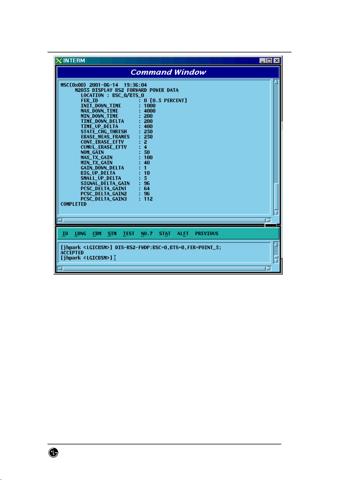
Fig. 4.3-27 Forward Link Power Management Information (RS2) Verification
SMD-011-PMA210
Page:199(877)
Issue:1.
Page 2

STAREX-IS BSM Manual
0
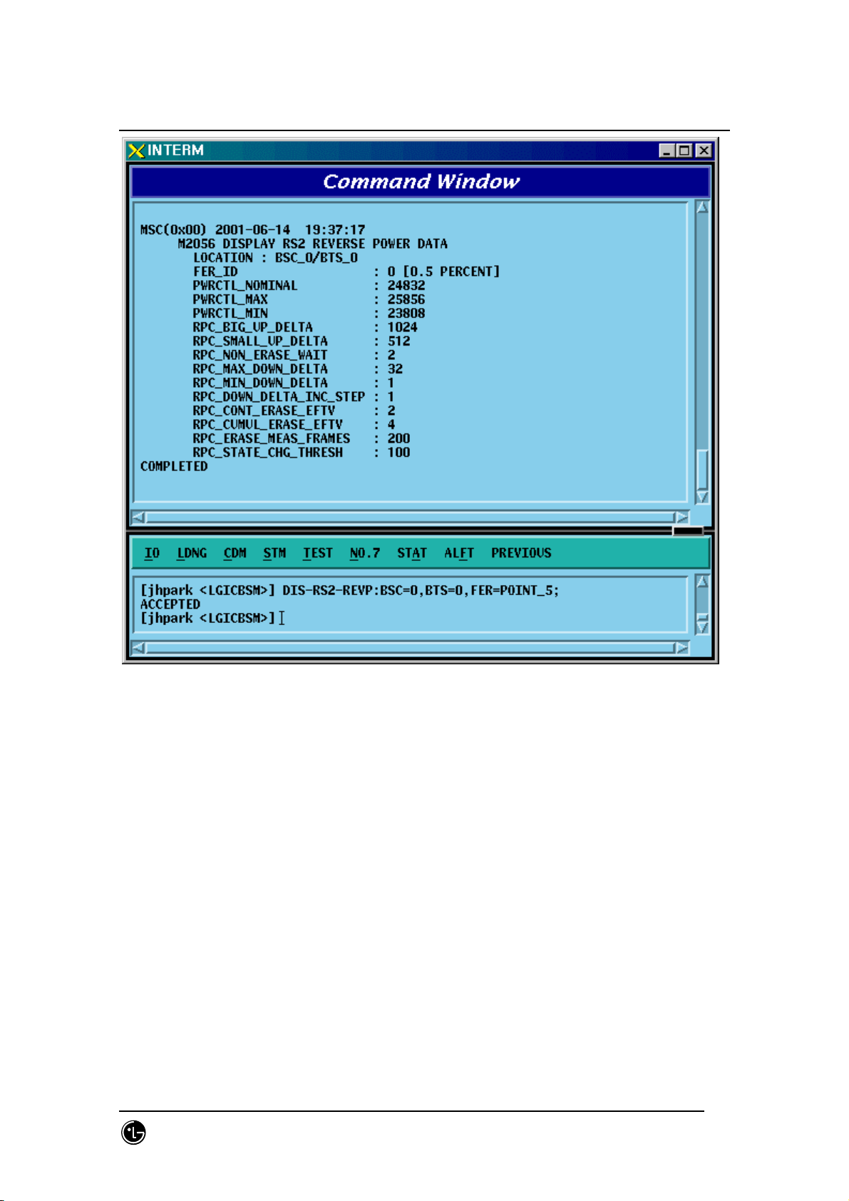
4.3.2.6. Backward Link Power Management Information (RS2)
Verification
Rate Set 2 transmits data at the speed of 14400,7200,3600,1800 bps. Input the
following command to check the parameter information for RS2 Backward Link Power
Management. Among the input values, FER (Frame Error Rate) has the value ranging
from 0.5%, 1 to 5%.
• Command DIS-RS2-REVP: BSC=a, BTS=b, FER=c;
a : BSC Number(0~11)
b: BTS Number(0~47)
c:FER
(POINT_5/PERCENT_1/PERCENT_2/PERCENT_3/PERCENT_4/PERCET_5)
• Input DIS-RS2-REVP: BSC=0, BTS=0, FER=POINT_5;
• Output
SMD-011-PMA210
Page:200(877)
Issue:1.
Page 3
STAREX-IS BSM Manual
0
Fig. 4.3-28 Backward Link Power Management Information (RS2) Verification
SMD-011-PMA210
Page:201(877)
Issue:1.
Page 4

STAREX-IS BSM Manual
0
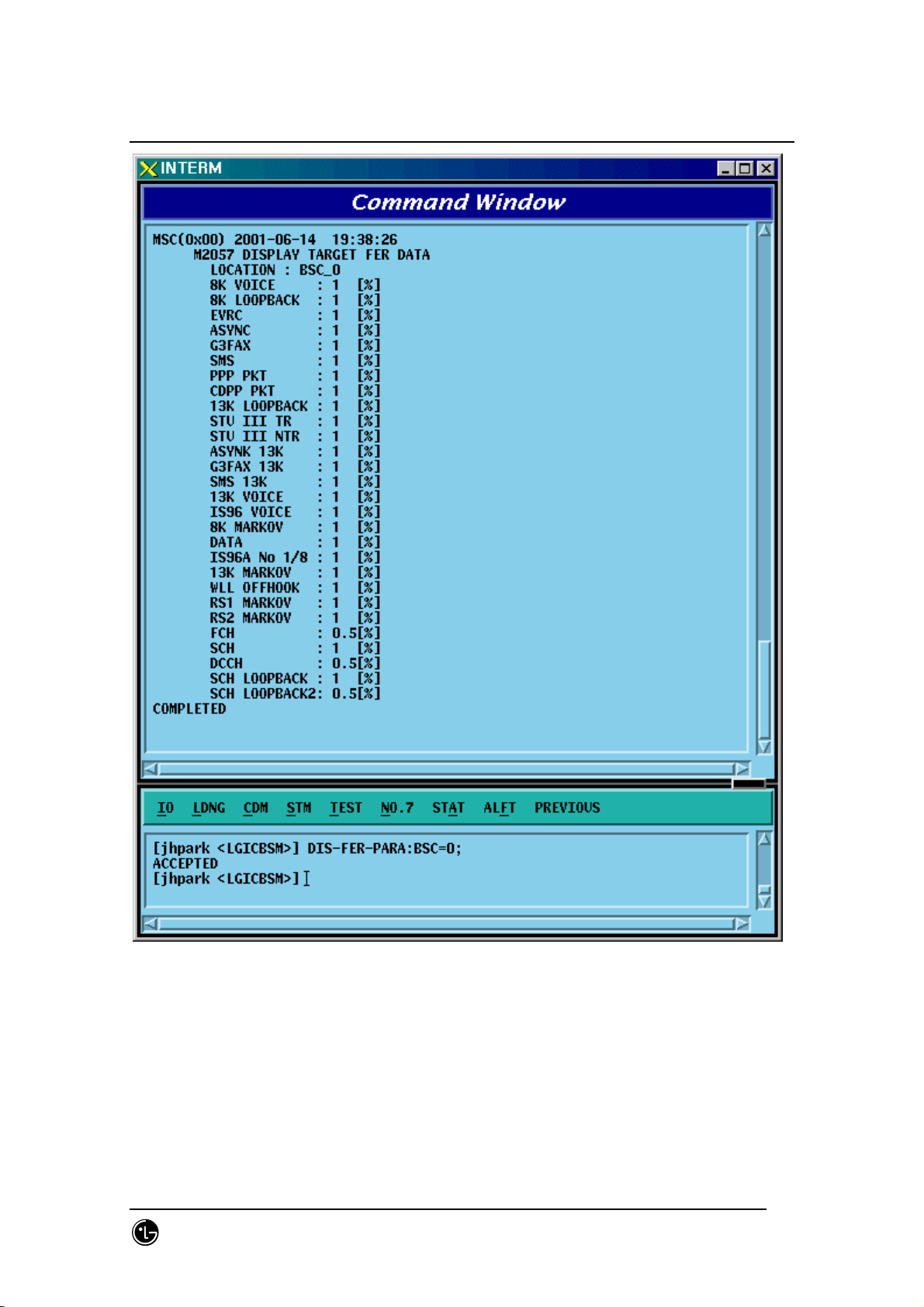
4.3.2.7. Service Option FER Verification
Target FER can be designated by the Service Option. Input the following command to
display this information. In the next display, 1% Target FER is applied for the "8K
VOICE" Service Option and for this, the following power management information is
used: RS1 forward link power management information, RS1 backward link power
management information, RS2 forward link power management information, and RS2
backward (or reverse-direction) link power management information.
• Command DIS-FER-PARA: BSC=a;
a : BSC Number(0~11)
• Input DIS-FER-PARA: BSC=0;
• Output
SMD-011-PMA210
Page:202(877)
Issue:1.
Page 5
STAREX-IS BSM Manual
0
Fig. 4.3-29 Service Option FER Verification
SMD-011-PMA210
Page:203(877)
Issue:1.
Page 6
STAREX-IS BSM Manual
0
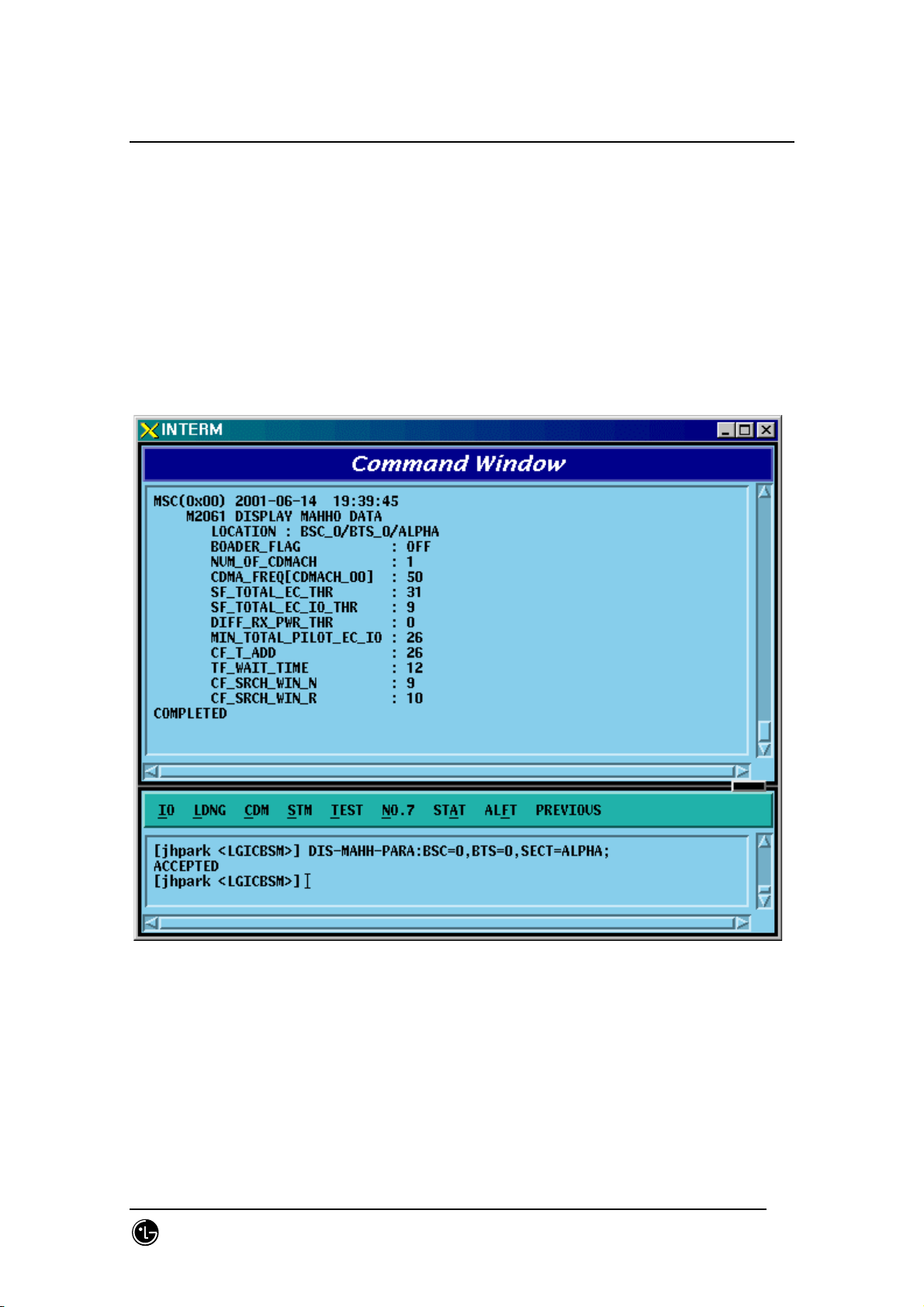
4.3.2.8. MAHHO Verification
• Command DIS-MAHH-PARA: BSC=a, BTS=b, SECT=c;
a : BSC Number(0~11)
b: BTS Number(0~47)
c: Sector Id .(ALPHA/BETA/GAMMA)
• Input DIS-MAHH-PARA: BSC=0,BTS=0,SECT=ALPHA;
• Output
Fig. 4.3-30 MAHHO Verification
SMD-011-PMA210
Page:204(877)
Issue:1.
Page 7
STAREX-IS BSM Manual
0
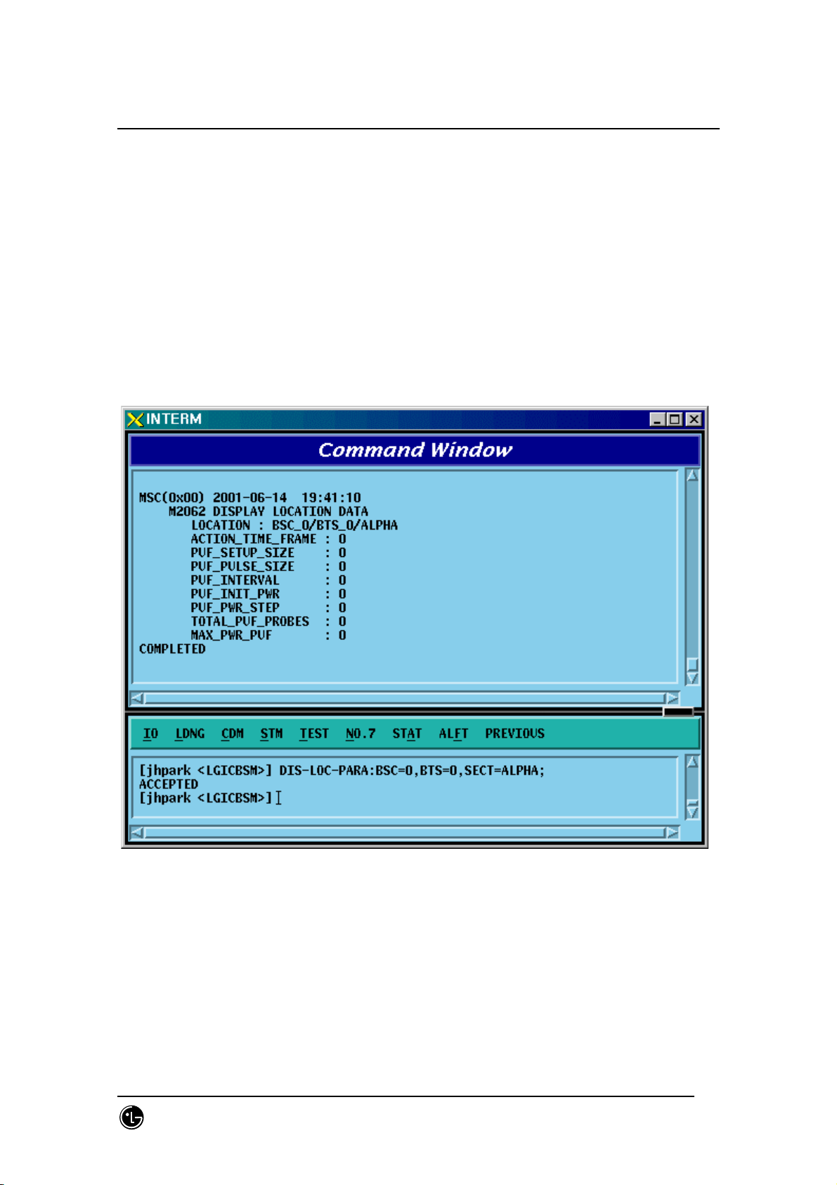
4.3.2.9. LOCATION Verification
• Command DIS-LOC-PARA: BSC=a, BTS=b, SECT=c;
a : BSC Number(0~11)
b: BTS Number(0~47)
c: Sector Id .(ALPHA/BETA/GAMMA)
• Input DIS-LOC-PARA: BSC=0,BTS=0,SECT=ALPHA;
• Output
Fig. 4.3-31 LOCATION Verification
SMD-011-PMA210
Page:205(877)
Issue:1.
Page 8
STAREX-IS BSM Manual
0
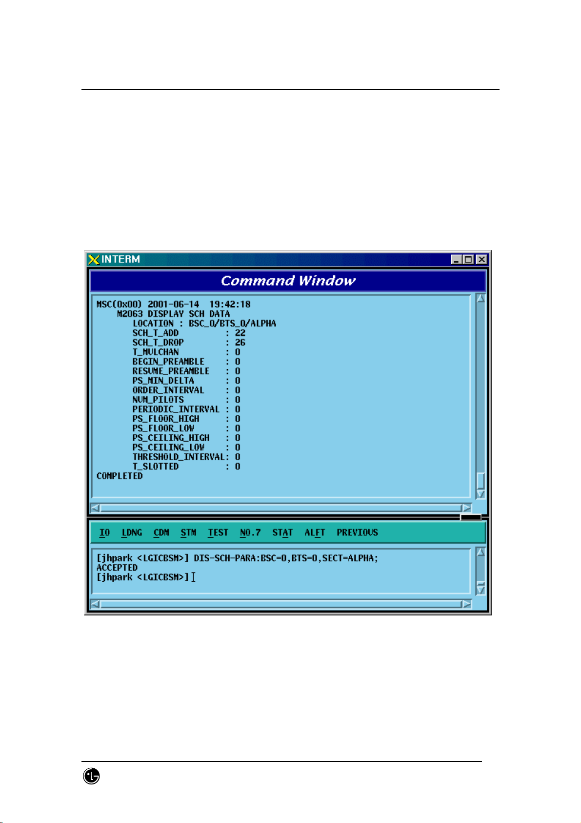
4.3.2.10. SCH Verification
• Command DIS-SCH-PARA: BSC=a, BTS=b, SECT=c;
a : BSC Number(0~11)
b: BTS Number(0~47)
c: Sector Id .(ALPHA/BETA/GAMMA)
• Input DIS-SCH-PARA: BSC=0,BTS=0,SECT=ALPHA;
• Output
Fig. 4.3-32 SCH Verification
SMD-011-PMA210
Page:206(877)
Issue:1.
Page 9
STAREX-IS BSM Manual
0
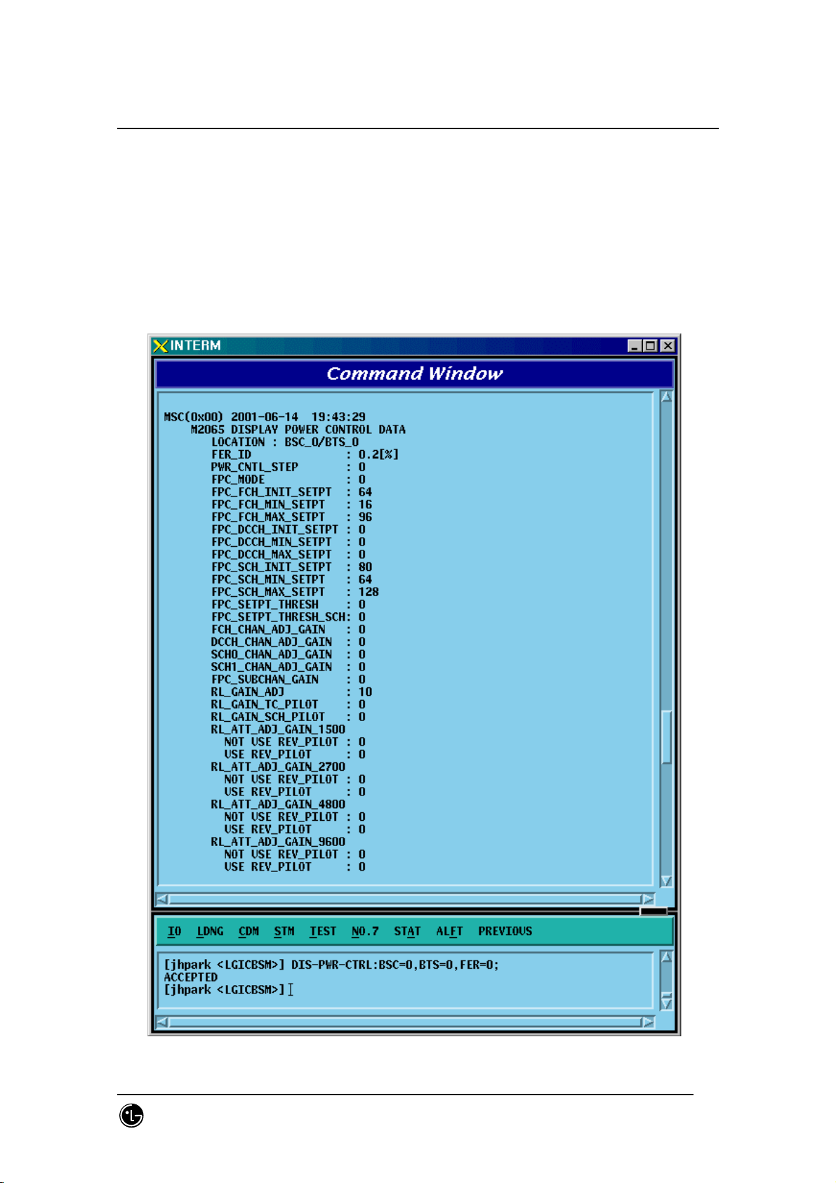
4.3.2.11. Power Control Data Verification
• Command DIS-PWR-CTRL: BSC=a, BTS=b, FER=c;
a : BSC Number(0~11)
b: BTS Number(0~47)
c: FER (0~30)
• Input DIS-PWR-CTRL: BSC=0, BTS=0,FER=0;
• Output
SMD-011-PMA210
Page:207(877)
Issue:1.
Page 10

STAREX-IS BSM Manual
0
Fig. 4.3-33 Power Control Data Verification
SMD-011-PMA210
Page:208(877)
Issue:1.
Page 11
STAREX-IS BSM Manual
0
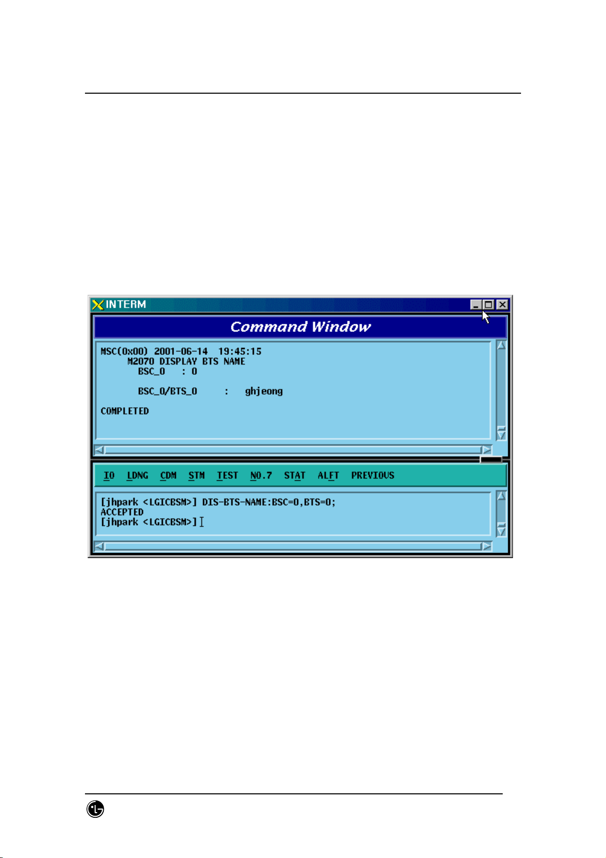
4.3.2.12. BTS Name Display
Input the following command to display the BTS name:
• Command DIS-BTS-NAME: BSC=a, BTS=b;
a : BSC Number(0~11)
b: BTS Number(0~47)
• Input DIS-BTS-NAME: BSC=0, BTS=0;
• Output
Fig. 4.3-34 BTS Name Display
SMD-011-PMA210
Page:209(877)
Issue:1.
Page 12
STAREX-IS BSM Manual
0
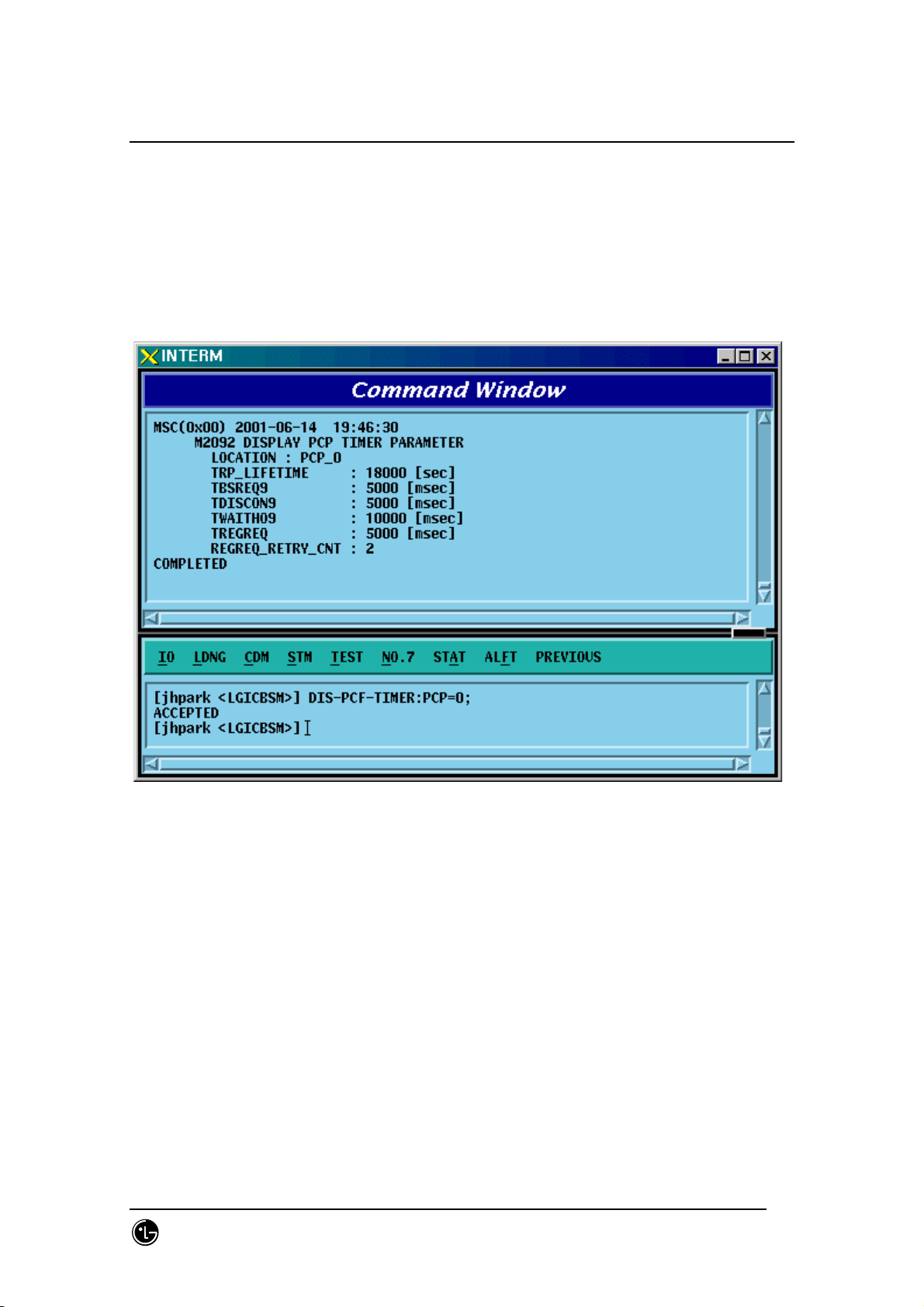
4.3.2.13. PCP Timer Information Verification
• Command DIS-PCF-TIMER:PCP =a;
a : PCP Number(0~2)
• Input DIS-PCF-TIMER: PCP=0;
• Output
Fig. 4.3-35 PCP Timer Information Verification
SMD-011-PMA210
Page:210(877)
Issue:1.
Page 13
STAREX-IS BSM Manual
0
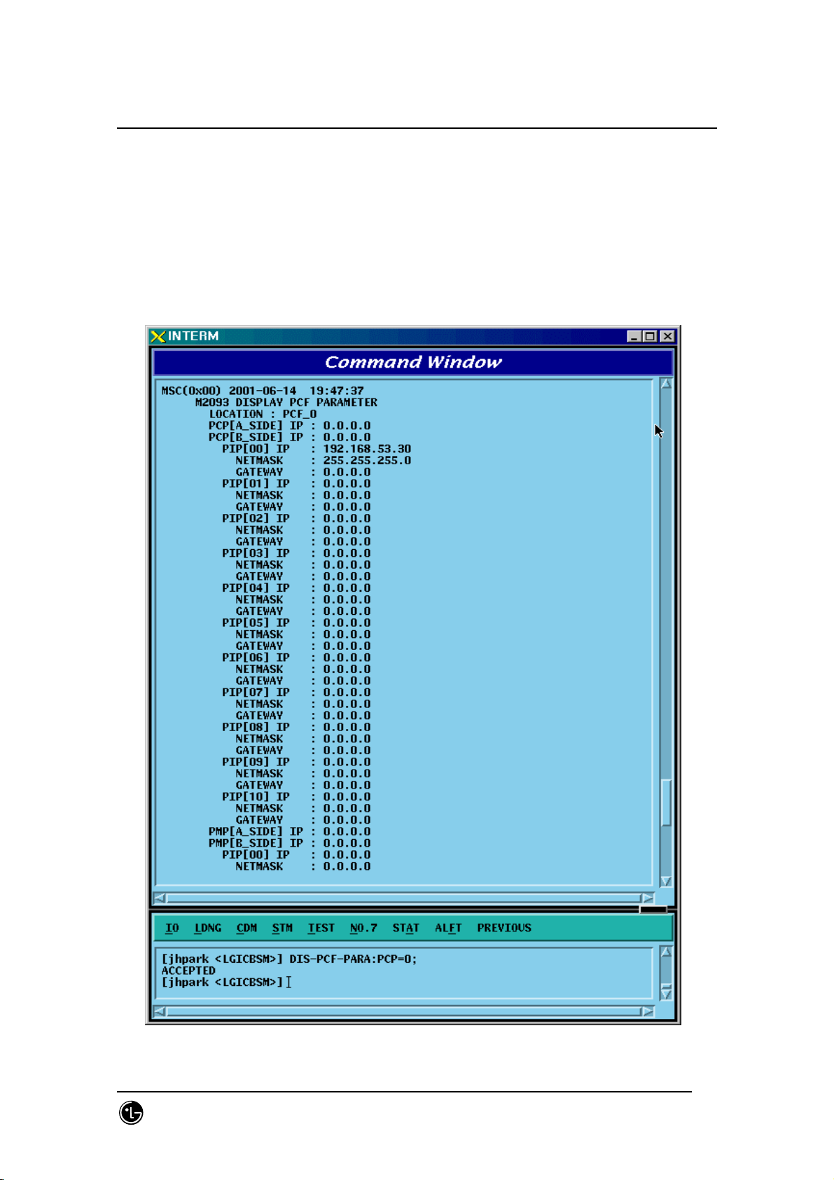
4.3.2.14. PCF Parameter Information Verification
• Command DIS-PCF-PARA :PCP =a;
a : PCP Number(0~2)
• Input DIS-PCF-PARA: PCP=0;
• Output
Fig. 4.3-36 PCF Parameter Information Verification
SMD-011-PMA210
Page:211(877)
Issue:1.
Page 14
STAREX-IS BSM Manual
0
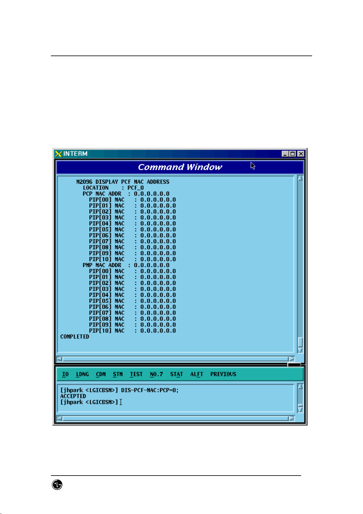
4.3.2.15. PCF MAC ADDRESS Information Verification
• Command DIS-PCF-MAC :PCP =a;
a : PCP Number(0~2)
• Input DIS-PCF-MAC: PCP=0;
• Output
Fig. 4.3-37 PCF MAC ADDRESS Information Verification
SMD-011-PMA210
Page:212(877)
Issue:1.
Page 15
STAREX-IS BSM Manual
0
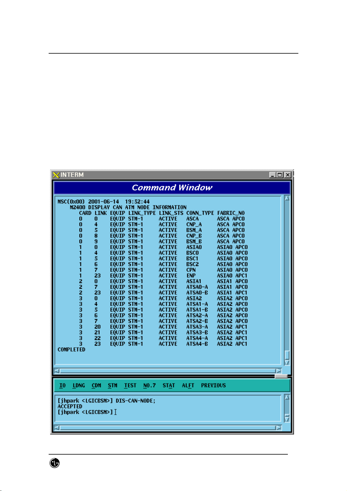
4.3.3. NETWORK Information Display
(Display_Parameter_Information_3)
4.3.3.1. CAN ATM NODE Information Display
• Command DIS-CAN-NODE;
• Output
SMD-011-PMA210
Page:213(877)
Issue:1.
Page 16

STAREX-IS BSM Manual
0
Fig. 4.3-38 CAN ATM NODE Information Display
SMD-011-PMA210
Page:214(877)
Issue:1.
Page 17
STAREX-IS BSM Manual
0
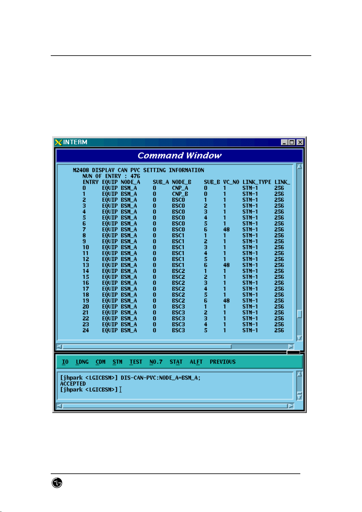
4.3.3.2. CAN PVC SETTING Information Display
• Command DIS-CAN-PVC;NODE_A=a;
• Input DIS-CAN-PVC: NODE_A=BSM_A;
a: BSM_A,BSM_B, BSC (0~11)
• Output
Fig. 4.3-39 CAN PVC SETTING Information Display
SMD-011-PMA210
Page:215(877)
Issue:1.
Page 18
STAREX-IS BSM Manual
0
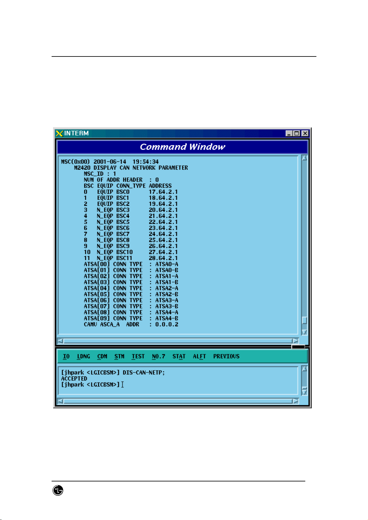
4.3.3.3. CAN NETWORK PARAMETER Information Display
• Command DIS-CAN-NETP;
• Input DIS-CAN-NETP;
• Output
Fig. 4.3-40 CAN NETWORK PARAMETER Information Display
SMD-011-PMA210
Page:216(877)
Issue:1.
Page 19
STAREX-IS BSM Manual
0
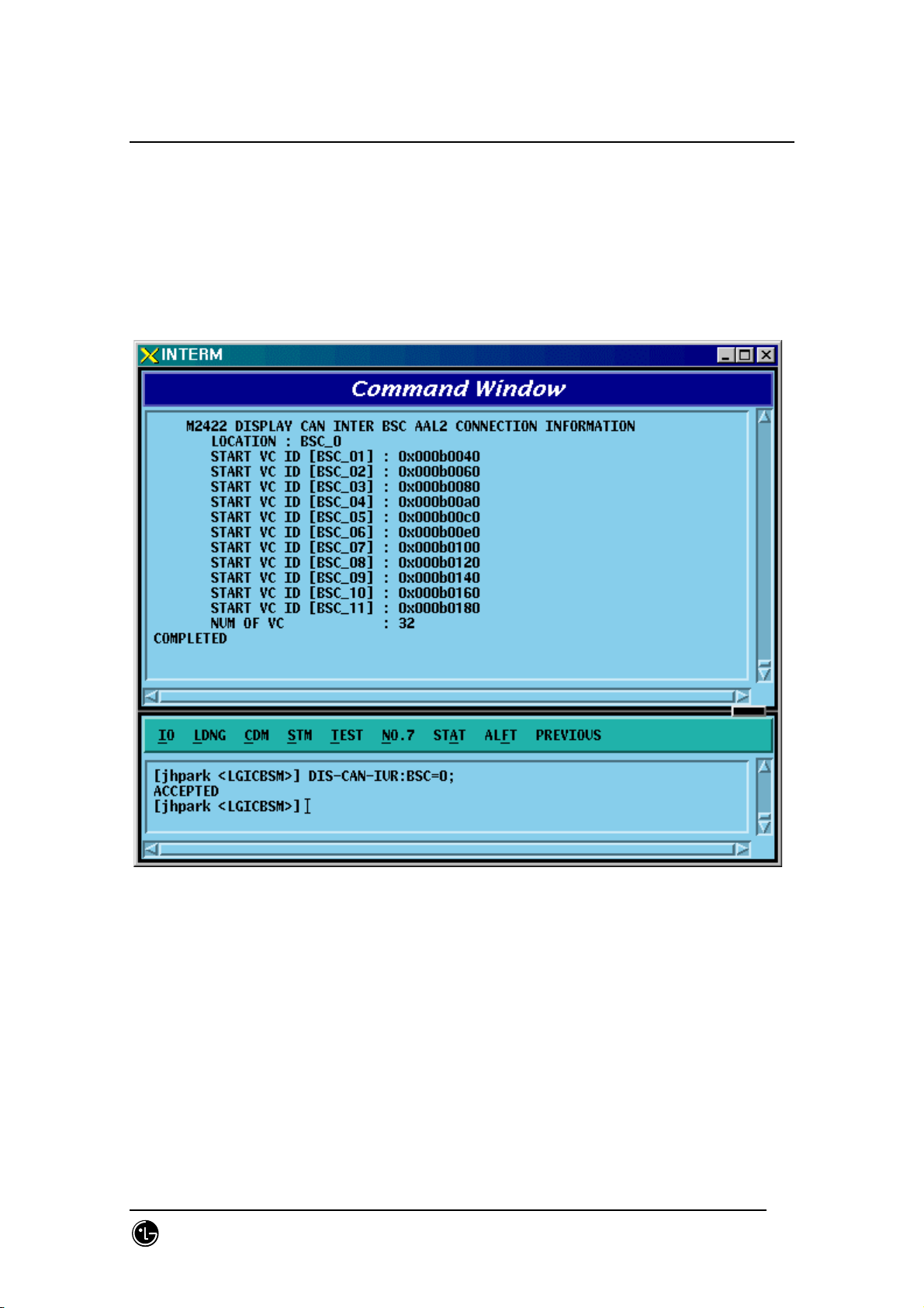
4.3.3.4. CAN INTER BSC AAL2 Setting Information Display
• Command DIS-CAN-IUR:BSC=a;
a:BSC Number (0~11)
• Input DIS-CAN-IUR:BSC=0;
• Output
Fig. 4.3-41 CAN INTER BSC AAL2 Setting Information Display
SMD-011-PMA210
Page:217(877)
Issue:1.
Page 20
STAREX-IS BSM Manual
0
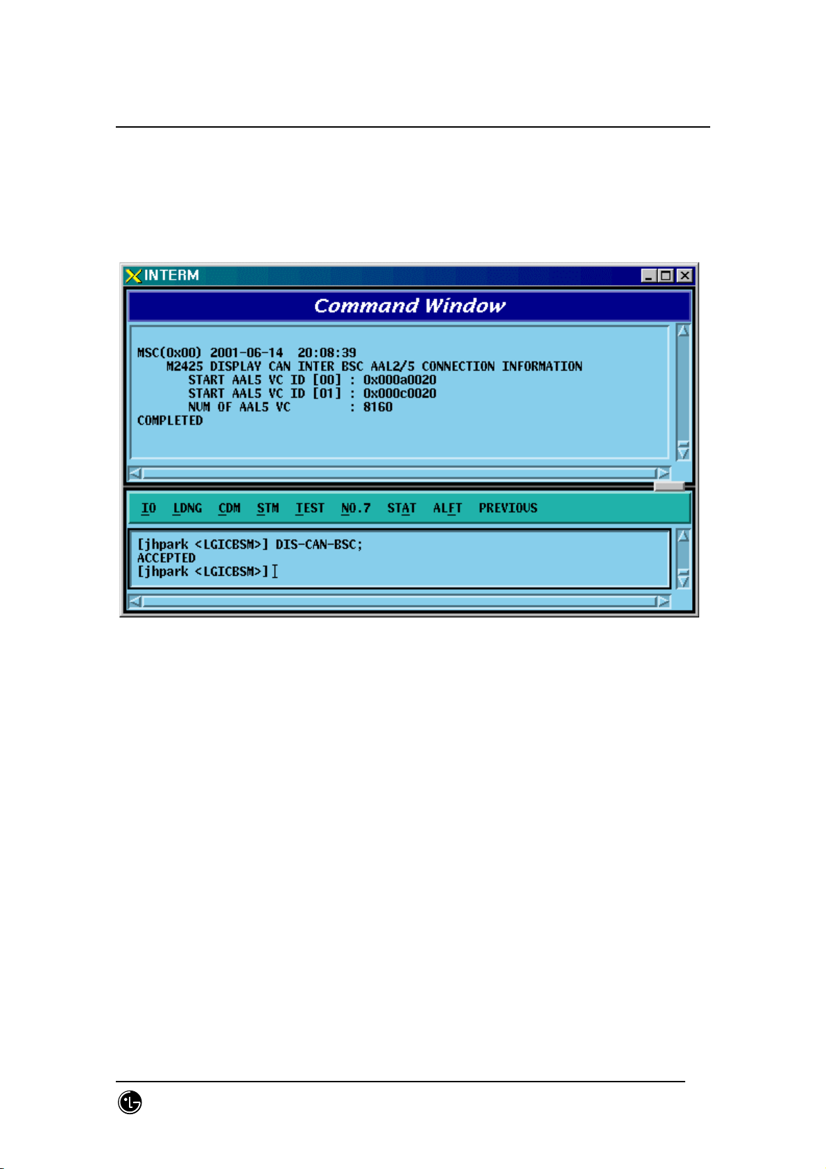
4.3.3.5. CAN INTER BSC AAL5 Setting Information Display
• Command DIS-CAN-BSC;
• Output
Fig. 4.3-42 CAN INTER BSC AAL5 Setting Information Display
SMD-011-PMA210
Page:218(877)
Issue:1.
Page 21
STAREX-IS BSM Manual
0
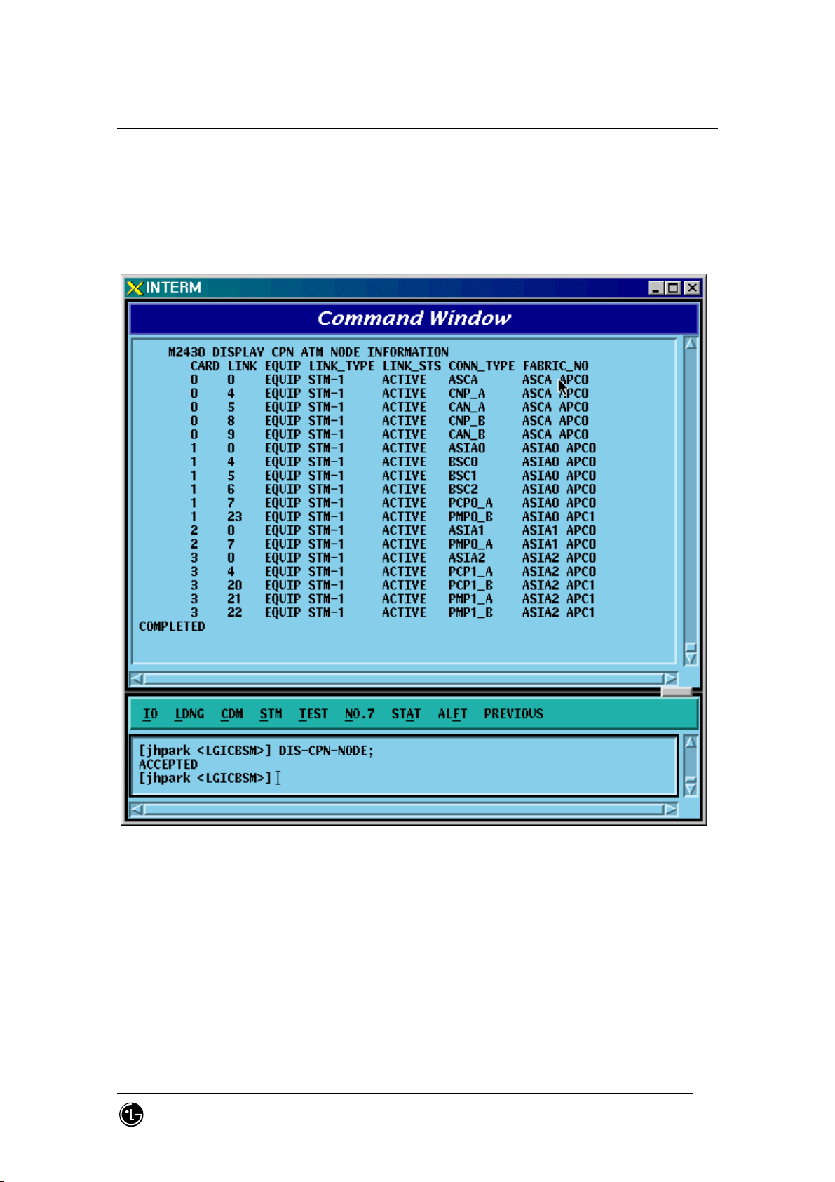
4.3.3.6. CAN ATM NODE Information Display
• Command DIS-CPN-NODE;
• Output
Fig. 4.3-43 CAN ATM NODE Information Display
SMD-011-PMA210
Page:219(877)
Issue:1.
Page 22
STAREX-IS BSM Manual
0
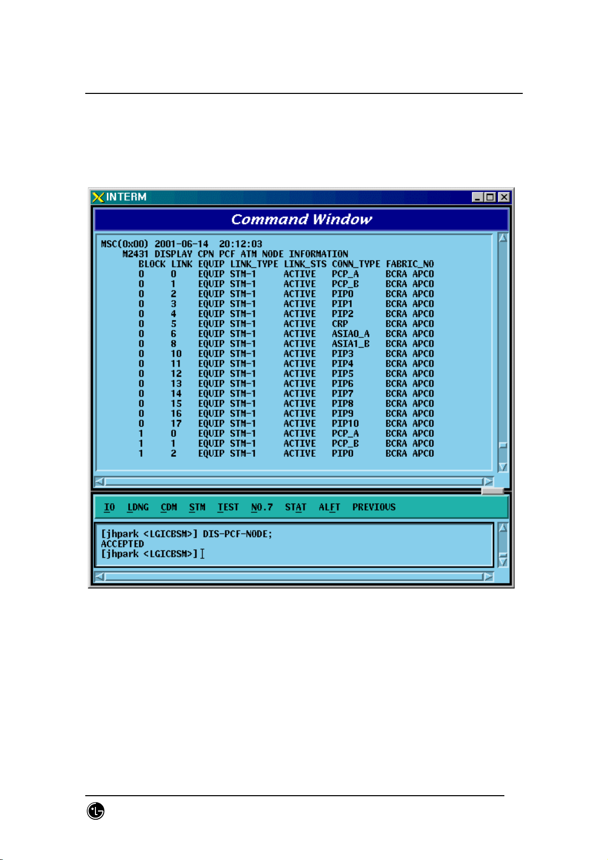
4.3.3.7. PCF ATM NODE Information Display
• Command DIS-PCF-NODE
• Output
Fig. 4.3-44 PCF ATM NODE Information Display
SMD-011-PMA210
Page:220(877)
Issue:1.
Page 23
STAREX-IS BSM Manual
0
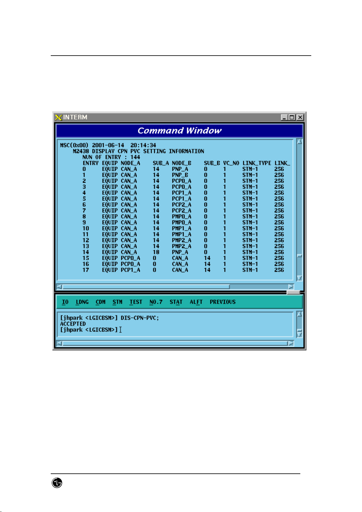
4.3.3.8. CAN PVC SETTING Information Display
• Command DIS-CPN-PVC
• Output
Fig. 4.3-45 CAN PVC SETTING Information Display
SMD-011-PMA210
Page:221(877)
Issue:1.
Page 24
STAREX-IS BSM Manual
0
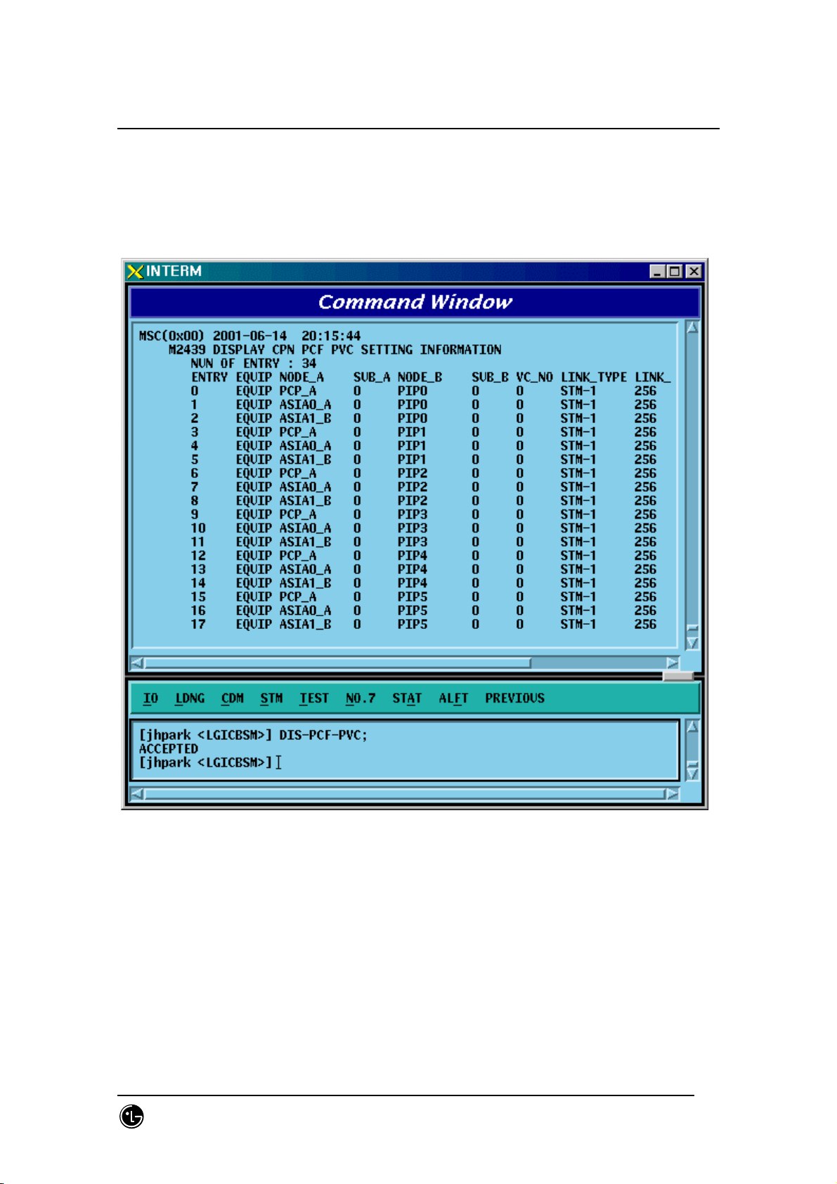
4.3.3.9. CAN PCF PVC SETTING Information Display
• Command DIS-PCF-PVC
• Output
Fig. 4.3-46 CAN PCF PVC SETTING Information Display
SMD-011-PMA210
Page:222(877)
Issue:1.
Page 25
STAREX-IS BSM Manual
0
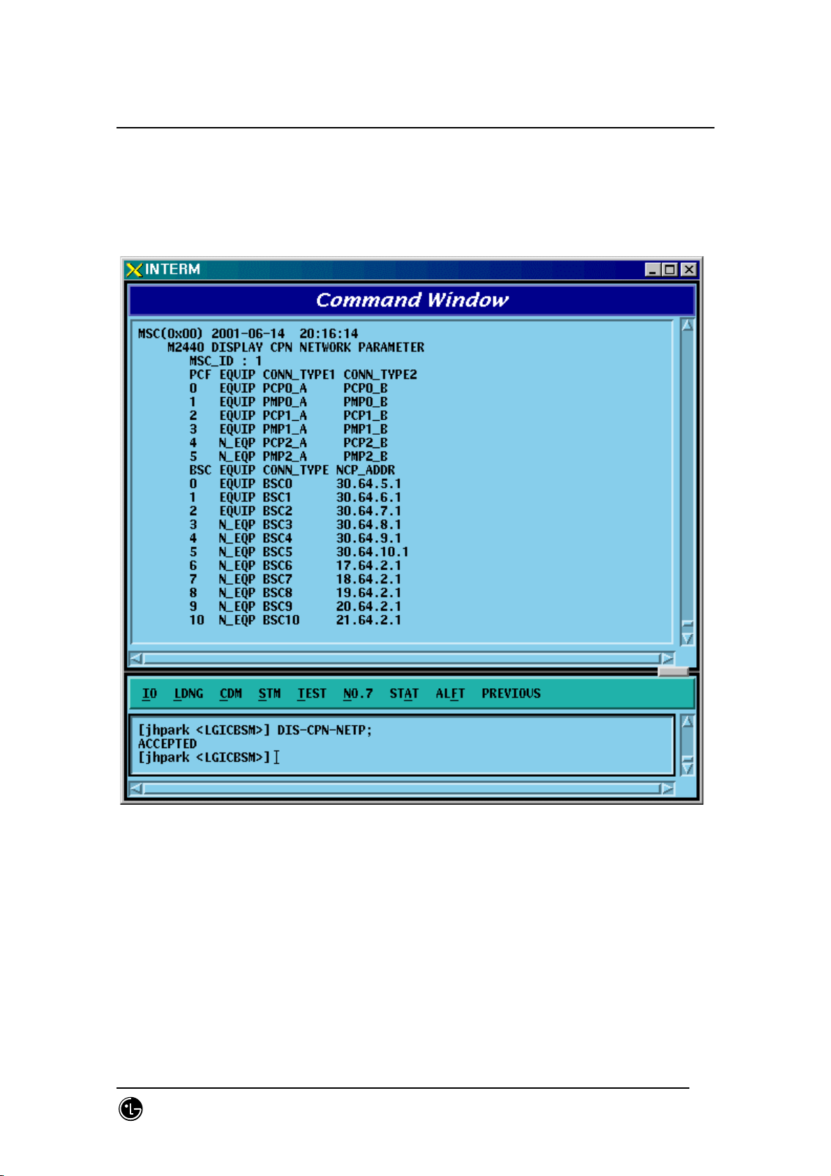
4.3.3.10. CPN METWORK PARAMETER Information Display
• Command DIS-CPN-NETP
• Output
Fig. 4.3-47 CPN METWORK PARAMETER Information Display
SMD-011-PMA210
Page:223(877)
Issue:1.
Page 26
STAREX-IS BSM Manual
0
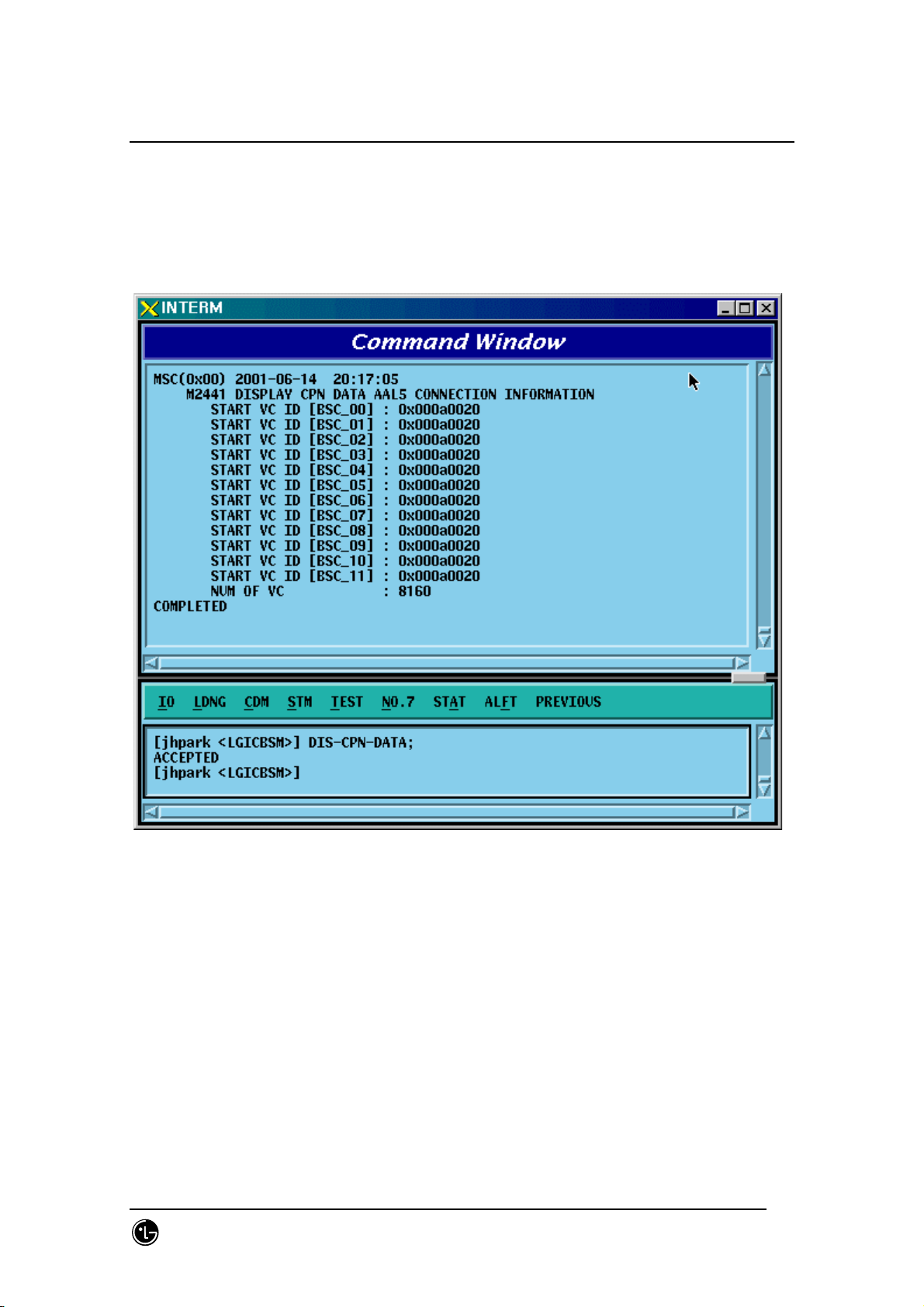
4.3.3.11. CPN DATA AAL2/5 Connection Information Display
• Command DIS-CPN-DATA;
• Output
Fig. 4.3-48 CPN DATA AAL2/5 Connection Information Display
SMD-011-PMA210
Page:224(877)
Issue:1.
Page 27
STAREX-IS BSM Manual
0
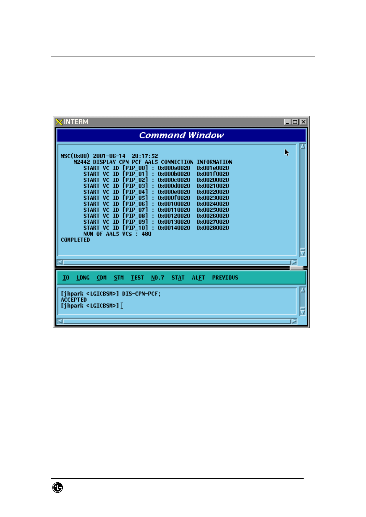
4.3.3.12. CPN PCF AAK2/5 Connection Information Display
• Command DIS-CPN-PCF;
• Output
Fig. 4.3-49 CPN PCF AAK2/5 Connection Information Display
SMD-011-PMA210
Page:225(877)
Issue:1.
Page 28
STAREX-IS BSM Manual
0
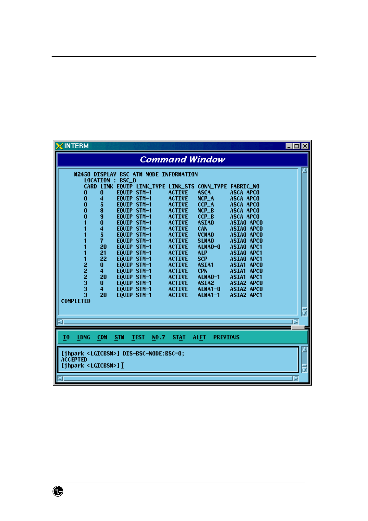
4.3.3.13. BSC ATM NODE Information Display
• Command DIS-BSC-NODE: BSC=a;
a: BSC Number (0~11)
• Input DIS-BSC-NODE: BSC=0;
• Output
Fig. 4.3-50 BSC ATM NODE Information Display
SMD-011-PMA210
Page:226(877)
Issue:1.
Page 29
STAREX-IS BSM Manual
0
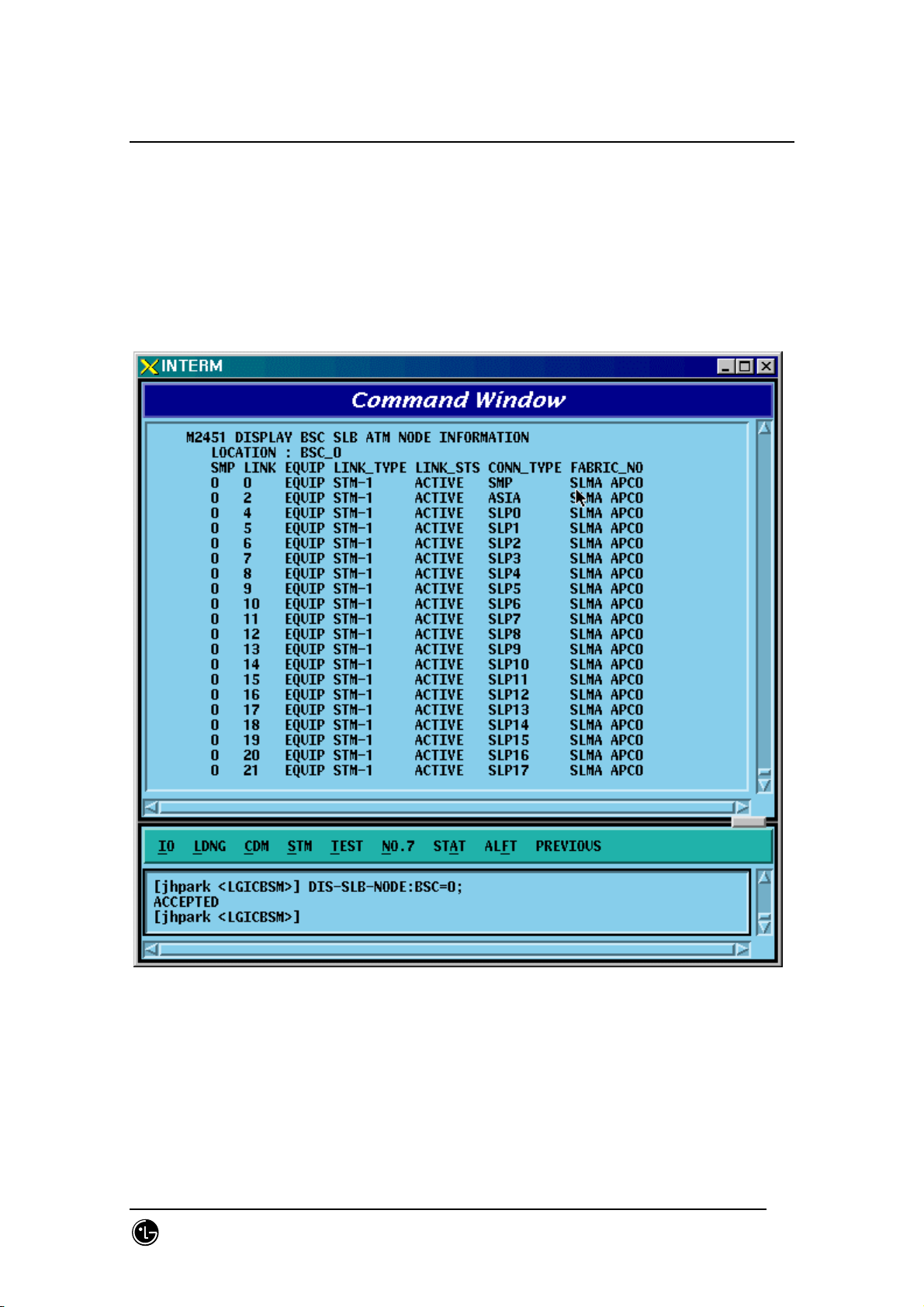
4.3.3.14. SLB ATM NODE Information Display
• Command DIS-SLB-NODE: BSC=a;
a: BSC Number (0~11)
• Input DIS-SLB-NODE: BSC=0;
• Output
Fig. 4.3-51 SLB ATM NODE Information Display
SMD-011-PMA210
Page:227(877)
Issue:1.
Page 30
STAREX-IS BSM Manual
0
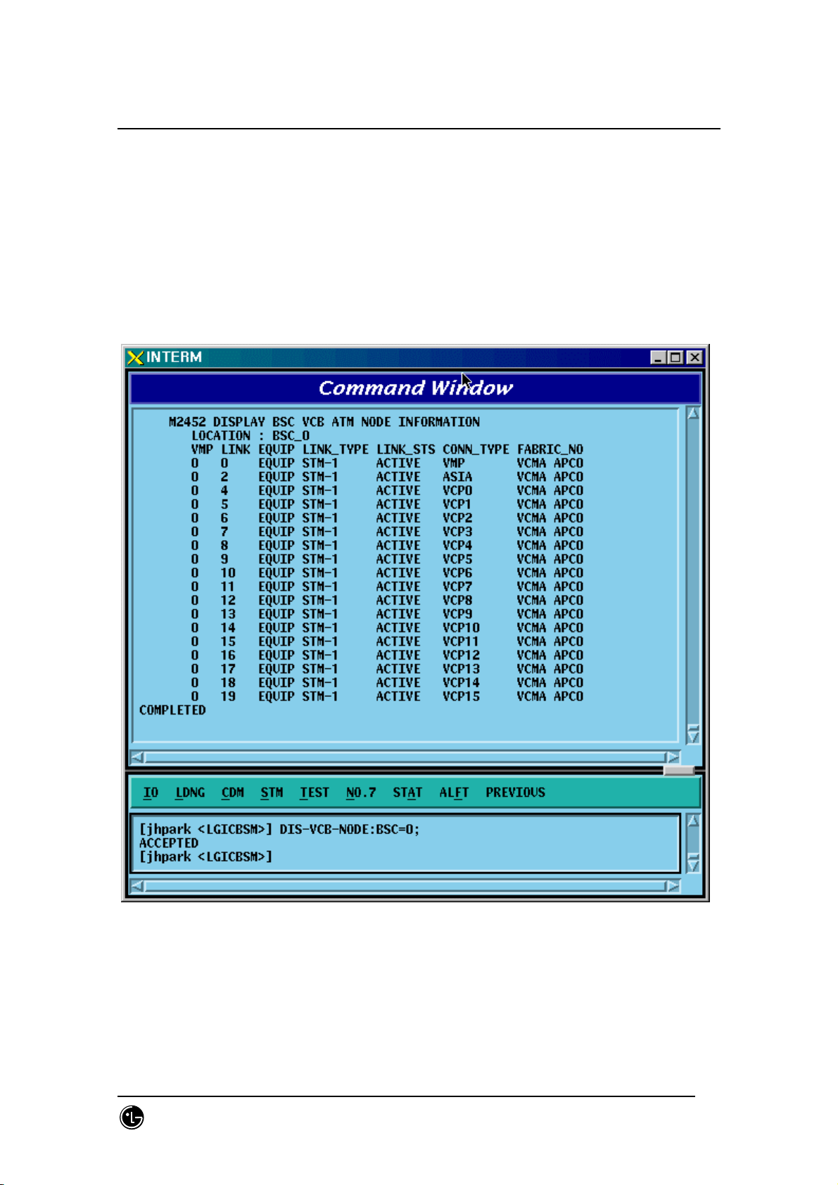
4.3.3.15. VCB ATM NODE Information Display
• Command DIS-VCB-NODE: BSC=a;
a: BSC Number (0~11)
• Input DIS-VCB-NODE: BSC=0;
• Output
Fig. 4.3-52 VCB ATM NODE Information Display
SMD-011-PMA210
Page:228(877)
Issue:1.
Page 31

STAREX-IS BSM Manual
0
4.3.3.16. ALB ATM NODE Information Display
‘
• Command DIS-ALB-NODE: BSC=a;
a: BSC Number (0~11)
• Input DIS-ALB-NODE: BSC=0;
• Output
Fig. 4.3-53 ALB ATM NODE Information Display
SMD-011-PMA210
Page:229(877)
Issue:1.
Page 32

STAREX-IS BSM Manual
0
4.3.3.17. BTS ATM NODE Information Display
• Command DIS-BTS-NODE: BSC=a ,BTS=b;
a: BSC Number (0~11)
b: BTS Number (0~47)
• Input DIS-BSC-NODE: BSC=0,BTS=0;
• Output
Fig. 4.3-54 BTS ATM NODE Information Display
SMD-011-PMA210
Page:230(877)
Issue:1.
Page 33

STAREX-IS BSM Manual
0
4.3.3.18. BSC-BTS TRUNK Information Display
• Command DIS-TRNK-DATA: BSC=a;
a: BSC Number (0~11)
• Input DIS-TRNK-DATA: BSC=0;
• Output
Fig. 4.3-55 BSC-BTS TRUNK Information Display
SMD-011-PMA210
Page:231(877)
Issue:1.
Page 34

STAREX-IS BSM Manual
0
4.3.3.19. BSC PVC SETTING Information Display
• Command DIS-BSC-PVC: BSC=a,NODE_A=b;
a: BSC Number (0~11)
b: NCP_A, NCP_B, CCP_A, CCP_B, ALMA0_0 , ALMA0_1, ALMA1_0 ,
ALMA1_1,CAN,CPN,ALP
• Input DIS-BSC-PVC: BSC=0,NODE_A=NCP_A;
• Output
SMD-011-PMA210
Page:232(877)
Issue:1.
Page 35

STAREX-IS BSM Manual
0
Fig. 4.3-56 BSC PVC SETTING Information Display
SMD-011-PMA210
Page:233(877)
Issue:1.
Page 36

STAREX-IS BSM Manual
0
4.3.3.20. BSC SLB PVC SETTING Information Display
• Command DIS-SLB-PVC: BSC=a;
a: BSC Number (0~11)
• Input DIS-SLB-PVC: BSC=0;
• Output
Fig. 4.3-57 BSC SLB PVC SETTING Information Display
SMD-011-PMA210
Page:234(877)
Issue:1.
Page 37

STAREX-IS BSM Manual
0
4.3.3.21. BSC VCB PVC SETTING Information Display
• Command DIS-VCB-PVC: BSC=a;
a: BSC Number (0~11)
• Input DIS-VCB-PVC: BSC=0;
• Output
Fig. 4.3-58 BSC VCB PVC SETTING Information Display
SMD-011-PMA210
Page:235(877)
Issue:1.
Page 38

STAREX-IS BSM Manual
0
4.3.3.22. BSC ALB PVC SETTING Information Display
• Command DIS-ALB-PVC: BSC=a;
a: BSC Number (0~11)
• Input DIS-ALB-PVC: BSC=0;
• Output
Fig. 4.3-59 BSC ALB PVC SETTING Information Display
SMD-011-PMA210
Page:236(877)
Issue:1.
Page 39

STAREX-IS BSM Manual
0
4.3.3.23. BTS LOCAL PVC SETTING Information Display
• Command DIS-BTS-LPVC: BSC=a;
a: BSC Number (0~11)
• Input DIS-BTS-LPVC: BSC=0;
• Output
Fig. 4.3-60 BTS LOCAL PVC SETTING Information Display
SMD-011-PMA210
Page:237(877)
Issue:1.
Page 40

STAREX-IS BSM Manual
0
4.3.3.24. BTS OUTER PVC SETTING Information Display
• Command DIS-BTS-OPVC: BSC=a, BTS=b;
a: BSC Number (0~11)
b: BTS Number(0~47)
• Input DIS-BTS-OPVC: BSC=0, BTS=0;
• Output
Fig. 4.3-61 BTS OUTER PVC SETTING Information Display
SMD-011-PMA210
Page:238(877)
Issue:1.
Page 41

STAREX-IS BSM Manual
0
4.3.3.25. BSC NETWORK PARAMETER Information Display
• Command DIS-BSC-NETP: BSC=a;
a: BSC Number (0~11)
• Input DIS-BSC-NETP: BSC=0;
• Output
Fig. 4.3-62 BSC NETWORK PARAMETER Information Display
SMD-011-PMA210
Page:239(877)
Issue:1.
Page 42

STAREX-IS BSM Manual
0
4.3.3.26. BSC ALP NETWORK PARAMETER Information Display
• Command DIS-ALS-NETP: BSC=a;
a: BSC Number (0~11)
• Input DIS-ALS-NETP: BSC=0;
• Output
Fig. 4.3-63 BSC ALP NETWORK PARAMETER Information Display
SMD-011-PMA210
Page:240(877)
Issue:1.
Page 43

STAREX-IS BSM Manual
0
4.3.3.27. BSC INTER BSC AAL2 Information Display
• Command DIS-BSC-IUR: BSC=a;
a: BSC Number (0~11)
• Input DIS-BSC-IUR: BSC=0;
• Output
Fig. 4.3-64 BSC INTER BSC AAL2 Information Display
SMD-011-PMA210
Page:241(877)
Issue:1.
Page 44

STAREX-IS BSM Manual
0
4.3.3.28. BSC INTER BTS AAL2 Information Display
• Command DIS-BSC-IUB: BSC=a, BTS=b;
a: BSC Number (0~11)
b: BTS Number(0~47)
• Input DIS-BSC-IUB: BSC=0, BTS=0;
• Output
Fig. 4.3-65 BSC INTER BTS AAL2 Information Display
SMD-011-PMA210
Page:242(877)
Issue:1.
Page 45

STAREX-IS BSM Manual
0
4.3.3.29. BSC INTER CAN AAL2/5 Information Display
• Command DIS-BSC-CAN: BSC=a;
a: BSC Number (0~11)
• Input DIS-BSC-CAN: BSC=0;
• Output
Fig. 4.3-66 BSC INTER CAN AAL2/5 Information Display
SMD-011-PMA210
Page:243(877)
Issue:1.
Page 46

STAREX-IS BSM Manual
0
4.3.3.30. BSC INTER SLB AAL5 Information Display
• Command DIS-BSC-SLB: BSC=a;
a: BSC Number (0~11)
• Input DIS-BSC-SLB: BSC=0;
• Output’
Fig. 4.3-67 BSC INTER SLB AAL5 Information Display
SMD-011-PMA210
Page:244(877)
Issue:1.
Page 47

STAREX-IS BSM Manual
0
4.3.3.31. BSC INTER VCB AAL5 Information Display
• Command DIS-BSC-VCB: BSC=a;
a: BSC Number (0~11)
• Input DIS-BSC-VCB: BSC=0;
• Output
Fig. 4.3-68 BSC INTER VCB AAL5 Information Display
SMD-011-PMA210
Page:245(877)
Issue:1.
Page 48

STAREX-IS BSM Manual
0
4.3.3.32. BSC INTER ALB AAL5 Information Display
• Command DIS-BSC-ALB: BSC=a;
a: BSC Number (0~11)
• Input DIS-BSC-ALB: BSC=0;
• Output
Fig. 4.3-69 BSC INTER ALB AAL5 Information Display
SMD-011-PMA210
Page:246(877)
Issue:1.
Page 49

STAREX-IS BSM Manual
0
4.3.3.33. BTS NETWORK PARAMETER Information Display
• Command DIS-BTS-NETP: BSC=a ,BTS=b;
a: BSC Number (0~11)
b: BTS Number (0~47)
• Input DIS-BTS-NETP: BSC=0,BTS=0;
• Output
Fig. 4.3-70 BTS NETWORK PARAMETER Information Display
SMD-011-PMA210
Page:247(877)
Issue:1.
Page 50

STAREX-IS BSM Manual
0
4.3.3.34. BTS INTER BTS AAL2 Information Display
• Command DIS-BTS-IUB: BSC=a ,BTS=b;
a: BSC Number (0~11)
b: BTS Number (0~47)
• Input DIS-BTS-IUB: BSC=0,BTS=0;
• Output
Fig. 4.3-71 BTS INTER BTS AAL2 Information Display
SMD-011-PMA210
Page:248(877)
Issue:1.
Page 51

STAREX-IS BSM Manual
0
4.3.3.35. BTS INTER RCU AAL5 Information Display
• Command DIS-BTS-RCU: BSC=a ,BTS=b;
a: BSC Number (0~11)
b: BTS Number (0~47)
• Input DIS-BTS-RCU: BSC=0,BTS=0;
• Output
Fig. 4.3-72 BTS INTER RCU AAL5 Information Display
SMD-011-PMA210
Page:249(877)
Issue:1.
Page 52

STAREX-IS BSM Manual
0
4.3.4. Parameter Information Change Command
(Change_Parameter_Information_1)
This section describes commands that are used to change the parameter information
that is inquired. The command to change parameter information cannot be easily input
by the keyboard since input parameter counts are too many. For this reason, this
section will skip the command input in Text and demonstrate window input by mouse.
Upon inputting the command, the part in blue is the parameter that the user can change
and the user can change part or entire fields among them. For details of each
parameter that is input, refer to Appendix.
SMD-011-PMA210
Page:250(877)
Issue:1.
Page 53

STAREX-IS BSM Manual
0
Table 4.3-1 Parameter Data Change Command (1) List
2201 CHG-BTS-DATA BTS parameter data change
2202 CHG-SECT-DATA SECTOR Parameter data change
2203 CHG-CHAN-DATA CDMA CHANNEL parameter data Change
2205 CHG-SYS1-PARA SYSTEM PARAMETER(1) change
2206 CHG-SYS2-PARA SYSTEM PARAMETER(2) change
2207 CHG-EXT1-SYS EXTENDED SYSTEM PARAMETER(1) change
2208 CHG-EXT2-SYS EXTENDED SYSTEM PARAMETER(2) change
2209 ADD-NGBR-DATA Addition of Neighbor cell data
2210 RMV-NGBR-DATA Deletion of Neighbor cell data
2211 CHG-NGBR-DATA Neighbor cell data change
2213 CHG-NGBR-BCON HOPPING BEACON PARAMETER change
2214 CHG-QOS-PARA QOS parameter data change
2216 CHG-CHIP-PWR Chip Power Control data change
2222 CHG-TIC-DATA TIC parameter data change
2223 CHG-SECT-CHAN Sector CDMA Channel change
2224 CHG-PWR-PARA Power control parameter data change
2225 CHG-AC-PARA ACCESS CHANNEL parameter information change
2226 CHG-TXMS-PARA TXMS parameter data change
2227 START-BTS-CALB BTS CALIBRATION start
2229 CHG-GSRM-PARA PC GLOBAL REDIRECT parameter change
2230 CHG-ACC-PARA ACCESS PARAMETER change
2232 CHG-PC-PARA PAGING CHANNEL parameter data change
2233 CHG-PICH-PARA PILOT CHANNEL parameter data change
2236 CHG-SC-PARA SYNC CHANNEL parameter data change
2238 CHG-QPC-PARA QUICH PAGING CHANNEL parameter data change
2239 CHG-BCON-PARA
HOPPING PILOT BEACON CHANNEL parameter data
change
SMD-011-PMA210
Page:251(877)
Issue:1.
Page 54

STAREX-IS BSM Manual
0
4.3.4.1. BTS Parameter Information Change
To change the BTS parameter information, click CDM->Change_Parameter_
Information->Change BTS Data on the Command Window in order and input the value
that the command wants to change in each field.
• Command CHG-BTS-DATA :BSC=a ,BTS=b [,SID=c] [,NID=d] [,BASE_ID=e]
[,BASE_CLASS=f] [,REG_ZONE=g] [,LTM_OFF=h]
[,DAY_LT=i] [,BASE_LAT=j] [,BASE_LONG=k]
[,TUB_ENC=l] [,REV_PWR=m];
• Input CHG-BTS-DATA :BSC=0 ,BTS=0 ,SID=3333;
• Output
SMD-011-PMA210
Page:252(877)
Issue:1.
Page 55

STAREX-IS BSM Manual
0
Fig. 4.3-73 BTS Parameter Information Display
4.3.4.2. Sector Parameter Information Change
To change the sector parameter information, click CDM->Change_Parameter_
Information_1->
input window is displayed, then input the value to be changed.
• Command CHG-SECT-DATA :BSC=a ,BTS=b ,SECT=c [,PN=d]
[,CNTL_PARA=e] ;
• Input CHG-SECT-DATA :BSC=0 ,BTS=0 ,SECT=ALPHA ,PN=40;
• Output
CHG-SECT-DATA on the Command Window in order. If the next
Fig. 4.3-74 Sector Parameter Information Change
SMD-011-PMA210
Page:253(877)
Issue:1.
Page 56

STAREX-IS BSM Manual
0
4.3.4.3. CDMA Channel Parameter Information Change
To change the CDMA parameter information, click CDM->Change_Parameter_
Information_1-> CHG-CHAN-DATA on the Command Window in order. If the next
input window is displayed, then input the value to be changed.
• Command CHG-CHAN-DATA :BSC=a ,BTS=b ,CDMACH=c
[,FREQ_BAND=d] [,CH_NUM=e] [,TCE_4HO=f] [,MAX_SCH=g];
• Input CHG-CHAN-DATA :BSC=0,BTS=0 ,CDMACH=0 ,FREQ_BAND=2222;
• Output
Fig. 4.3-75 CDMA Channel Parameter Information Display
SMD-011-PMA210
Page:254(877)
Issue:1.
Page 57

STAREX-IS BSM Manual
0
4.3.4.4. SYSTEM PARAMETER(1) Change
To change the system parameter message, click CDM->
Change_Parameter_Information_1-> CHG-SYS1-PARA on the Command Window in
order. As the System Parameter Message have many elements, they are divided into
the three commands. The output format for each command is the same.
• Command CHG-SYS1-PARA :BSC=a ,BTS=b ,SECT=c ,CDMACH=d [,TOT_ZONE=e]
[,ZONE_TIME=f] [,MULT_SIDS=g] [,MULT_NIDS=h]
[,REP_THSH=i] [,REP_FRAM=j] [,SRCH_WINA=k]
[,SRCH_WINN=l] [,SRCH_WINR=m] [,NGHB_MAGE=n] [,T_ADD=o]
[,T_DROP=p] [,T_COMP=q] [,T_TDRP=r];
• Input CHG-SYS1-PARA :BSC=0,BTS=0 ,SECT=ALPHA,CDMACH=0,TOT_ZONE=5
• Output
SMD-011-PMA210
Page:255(877)
Issue:1.
Page 58

STAREX-IS BSM Manual
0
Fig. 4.3-76 System Parameter Change(1) Display
4.3.4.5. SYSTEM
4.3.4.6. PARAMETER(2) Change
To change the system parameter message, click CDM->
Change_Parameter_Information_1-> CHG-SYS2-PARA on the Command Window in
order. Since the System Parameter Message have many elements, they are divided
into three commands. The output format for each command is the same.
• Input CHG-SYS2-PARA :BSC=a ,BTS=b ,SECT=c ,CDMACH=d [,HOME_REG=e]
[,MAX_SCI=f] [,NID_REG=g] [,SID_REG=h] [,PARM_REG=i] [,REG_PRD=j]
[,REG_DIST=k] [,PWR_UP=l] [,PWR_DOWN=m]
[,THSH_EABL=n] [,PRID_EABL=o] [,REP_DELY=p]
[,RE_SCAN=q] [,EXT_SYS=r] [,EXT_NGHBR=s] [,GEN_NGHBR=t]
[,REDIRECT=u] [,PRI_NGHBR=v] [,USER_ZONE=w]
[,EXT_REDIRECT=x] [,EXT_CHAN=y] ;
• Output CHG-SYS2-PARA :BSC=0 ,BTS=0,SECT=ALPHA ,CDMACH=0,
HOME_REG=MANUAL;
• Display
SMD-011-PMA210
Page:256(877)
Issue:1.
Page 59

STAREX-IS BSM Manual
0
Fig. 4.3-77 System Parameter Change(2) Display
SMD-011-PMA210
Page:257(877)
Issue:1.
Page 60

STAREX-IS BSM Manual
0
4.3.4.7. EXTENDED SYSTEM PARAMETER(1) Change
To change the Extended System Parameter Message, click CDM->
Change_Parameter_Information_1-> CHG-EXT1-SYS on the Command Window in
order. If the next input window is displayed, then input the value to be changed.
• Change CHG-EXT1-SYS :BSC=a ,BTS=b ,SECT=c ,CDMACH=d [,PREF_MSID=e]
[,MCC=f] [,IMSI_11_12=g] [,TMSI_LEN=h]
[,TMSI_ZONE_1=i] [,TMSI_ZONE_2=j] [,TMSI_ZONE_3=k]
[,TMSI_ZONE_4=l] [,TMSI_ZONE_5=m]
[,TMSI_ZONE_6=n] [,TMSI_ZONE_7=o]
[,TMSI_ZONE_8=p] [,BCAST_IDX=q] [,SOFT_SLOPE=r]
[,ADD_INT=s] [,DROP_INT=t] [,NGBR_SET=u]
[,ACCESS_HO=v] [,HO_MSG_RSP=w] [,ACC_PRB_HO=x] [,PRB_HO_OT=y] ;
• Input CHG-EXT1-SYS :BSC=0 ,BTS=0 ,SECT=ALPHA ,CDMACH=0 ,
PREF_MSID=IMSI;
• Output
SMD-011-PMA210
Page:258(877)
Issue:1.
Page 61

STAREX-IS BSM Manual
0
Fig. 4.3-78 Extended System Parameter Change(1) Display
SMD-011-PMA210
Page:259(877)
Issue:1.
Page 62

STAREX-IS BSM Manual
0
4.3.4.8. EXTENDED SYSTEM PARAMETER(2) Change
To change the Extended System Parameter Message, click CDM->
Change_Parameter_Information_1-> CHG-EXT2-SYS on the Command Window in
order. If the next input window is displayed, then input the value to be changed.
• Command CHG-EXT2-SYS :BSC=a ,BTS=b ,SECT=c ,CDMACH=d
[,IMSI_T_SUPRT=e]
[,P_REV=f] [,MIN_P_REV=g] [,MAX_ALT_SO=h]
[,RESEL_INCL=i] [,EC_THRESH=j]
[,EC_IO_THRESH=k] [,PILOT_REPORT=l]
[,NGBR_SET_INF=m] [,ACC_HO_ORD=n] [,HO_LIST_UPD=o]
[,MAX_PRB_HO=p] [,BRD_GPS_ASS=q] [,QPC_SUPPORT=r] [,NUM_QPCH=s]
[,QPCH_RATE=t] [,QPC_PWR_LEV=u] [,QPC_CCI=v] [,QPC_PWR_CFG=w]
[,SDB_SUPPORT=x] [,MAC_CF_SPRT=y] [,RLGAIN_PICH=z];
• Input CHG-EXT2-SYS :BSC=0 ,BTS=0,SECT=ALPHA ,CDMACH=,IMSI_T_SUPRT=1;
• Output
SMD-011-PMA210
Page:260(877)
Issue:1.
Page 63

STAREX-IS BSM Manual
0
Fig. 4.3-79 Extended System Parameter Change(2) Display
SMD-011-PMA210
Page:261(877)
Issue:1.
Page 64

STAREX-IS BSM Manual
0
4.3.4.9. Neighbor Cell Information Addition
To add the neighbor list, click the CDM->Change_Parameter_Information_1-> ADD-
NGBR-DATA on the Command Window in order. If the next input window is displayed,
then input the values to be changed.
• Command ADD-NGBR-DATA :BSC=a ,BTS=b ,SECT=c ,INDEX=d ,NGBR_CNFG=e
,NGBR_PN=f ,NGBR_SID=g ,NGBR_NID=h ,NGBR_BASE=i ,NGBR_MSC=j
,NGBR_BSC=k ,NGBR_BTS=l ,NGBR_SECT=m ,NGBR_MSC_T=n
,NGBR_BSC_T=o,NGBR_BCON=p ,SRCH_PRIO=q
,FREQ_INCL=r [,NGBR_BAND=s] [,NGBR_FREQ=t]
[,TIME_INCL=u] [,TX_OFFSET=v] [,TX_DURATION=w] [,TX_PERIOD=x]
[,SRCH_SET=y] [,ADD_PICH_REC=z] [,PICH_REC=] [,OTD_PWR=]
[,SRCH_OFFSET=] [,ACC_HO=] [,ACC_HO_ALW=];
• Input ADD-NGBR-DATA :BSC=0 ,BTS=0 ,SECT=ALPHA ,INDEX=0 ,NGBR_CNFG=0
,NGBR_PN=0 ,NGBR_SID=0 ,NGBR_NID=0 ,NGBR_BASE=0 ,NGBR_MSC=0
,NGBR_BSC=0 ,NGBR_BTS=0 ,NGBR_SECT=ALPHA ,NGBR_MSC_T=LG_MSC
,NGBR_BSC_T=LG_BSC,NGBR_BCON=NO ,SRCH_PRIO=LOW
,FREQ_INCL=NO,NGBR_BAND=Mhz_800;
• Output
SMD-011-PMA210
Page:262(877)
Issue:1.
Page 65

STAREX-IS BSM Manual
0
Fig. 4.3-80 Neighbor Cell Addition Display
4.3.4.10. Neighbor Cell Information Deletion
To delete the neighbor list, click CDM->Change_Parameter_Information_1-> RMV-
NGBR-DATA on the Command Window in order. If the next window is displayed, then
input the sector and PN value of the sector to be deleted.
• Command RMV-NGBR-DATA :BSC=a ,BTS=b ,SECT=c ,NGBR_PN=d;
• Input RMV-NGBR-DATA :BSC=0 ,BTS=0 ,SECT=ALPHA ,NGBR_PN=0;
• Output
Fig. 4.3-81 Neighbor Cell Information Deletion Display
SMD-011-PMA210
Page:263(877)
Issue:1.
Page 66

STAREX-IS BSM Manual
0
4.3.4.11. Neighbor Cell Information Change
To change the neighbor list, click CDM->Change_Parameter_Information_1-> CHG-
NGBR-DATA on the Command Window in order. If the next input Window is displayed,
input the sector and the PN value of the sector to be deleted.
• Command CHG-NGBR-
DATA :BSC=a ,BTS=b ,SECT=c ,NGBR_PN=d ,NEW_INDEX=e
• Input
• Output
SMD-011-PMA210
Page:264(877)
Issue:1.
Page 67

STAREX-IS BSM Manual
0
4.3.4.12. HOPPING BEACON PARAMETER Change
To change Hopping Beacon Parameter, click CDM->Change_Parameter_Information_1-
> CHG-NGBR-BCON on the Command Window in order.
• Command CHG-NGBR-BCON :BSC=a ,BTS=b ,SECT=c ,CDMACH=d
[,NGBR_SRCH=e]
[,USE_TIMING=f] [,G_TIME_INCL=g] [,G_TX_DURATE=h]
[,G_TX_PERIOD=i] [,SRCH_OFF_INC=j] ;
• Input CHG-NGBR-BCON :BSC=0 ,BTS=0 ,SECT=ALPHA ,CDMACH=0 ,
NGBR_SRCH=255;
• Output
Fig. 4.3-82 Hopping Beacon Parameter Change Display
SMD-011-PMA210
Page:265(877)
Issue:1.
Page 68

STAREX-IS BSM Manual
0
4.3.4.13. QOS Parameter Change
To change Quality Of Service parameter information, click CDM-
>Change_Parameter_Information_1-> CHG-QOS-PARA on the Command Window in
order.
• Command CHG-QOS-PARA :BSC=a ,BTS=b [,MAX_SCH_RATE=c];
• Input CHG-QOS-PARA :BSC=0 ,BTS=0,MAX_SCH_RATE=255;
• Output
Fig. 4.3-83 QOS Parameter Information Change Display
SMD-011-PMA210
Page:266(877)
Issue:1.
Page 69

STAREX-IS BSM Manual
0
4.3.4.14. Chip Power Control Information Change
To change Chip Power Control information, click CDM-
>Change_Parameter_Information_1-> CHG-CHIP-PWR on the Command Window in
order.
• Command CHG-CHIP-PWR :BSC=a ,BTS=b [,CH_PWR0=c] [,CH_PWR1=d]
[,CH_PWR2=e]
[,CH_PWR3=f] [,MIN_GAIN0=g] [,MIN_GAIN1=h] [,MIN_GAIN2=i]
[,MIN_GAIN3=j][,MAX_GAIN0=k] [,MAX_GAIN1=l] [,MAX_GAIN2=m]
[,MAX_GAIN3=n] [,STEP_UP_SIZE=o] [,STEP_DN_SIZE=p]
[,FPC_PUNC=q] [,RPC_PUNC=r] [,PWR_CNT_PNT=s] [,PWR_CNT_PTN=t] ;
• Input CHG-CHIP-PWR :BSC=0 ,BTS=0 ,CH_PWR0=255;
• Output
SMD-011-PMA210
Page:267(877)
Issue:1.
Page 70

STAREX-IS BSM Manual
0
Fig. 4.3-84 Chip Power Control Information Change Display
4.3.4.15. TIC Parameter Change
To change Tx Gain value, click CDM->Change_ Parameter_Information_1-> CHG-
TIC-DATA on the Command Window in order. If the next input window is displayed,
then input the value to be changed.
• Command CHG-TIC-DATA :BSC=a ,BTS=b ,SECT=c ,CDMACH=d [,TX_GAIN=e] ;
• Input CHG-TIC-DATA :BSC=0 ,BTS=0 ,SECT=ALPHA ,CDMACH=0 ,TX_GAIN=255 ;
• Output
SMD-011-PMA210
Page:268(877)
Issue:1.
Page 71

STAREX-IS BSM Manual
0
Fig. 4.3-85 TIC Parameter Information Change Display
SMD-011-PMA210
Page:269(877)
Issue:1.
Page 72

STAREX-IS BSM Manual
0
4.3.4.16. OCNS Parameter Change
To change OCNS Parameter value, click CDM->Change_ Parameter_Information_1->
CHG-OCNS-PARA on the Command Window in order. If the next input Window is
displayed, then input the value to be changed.
• Command CHG-OCNS-PARA :BSC=a ,BTS=b ,SECT=c ,CDMACH=d
[,OCNS_ENABLE=e]
[,NUM_OCNS_CH=f] [,OCNS_TEST=g] [,OCNS_SO=h];
• Input CHG-OCNS-PARA :BSC=0 ,BTS=0 ,SECT=ALPHA ,
CDMACH=0 ,OCNS_ENABLE=DISABLE,NUM_OCNS_CH=2;
• Output
Fig. 4.3-86 OCNS Parameter Change Display
SMD-011-PMA210
Page:270(877)
Issue:1.
Page 73

STAREX-IS BSM Manual
0
4.3.4.17. Power Control Information Change
To change OCNS Parameter value, click CDM->Change_ Parameter_Information_1->
CHG-PWR-PARA on the Command Window in order. If the next input Window is
displayed, then input the value to be changed.
• Command CHG-PWR-PARA :BSC=a ,BTS=b ,SECT=c ,CDMACH=d
[,T_RX_FILTER=e]
[,G_RX_FILTER=f] [,G_TX_FILTER=g] [,GH_TX_FILTER=h]
[,R_TX_PILOT=i] [,FLN_BLK_THSH=j] [,FLN_HO_THSH=k]
[,FLN_GAIN_SCA=l] [,RLN_BLK_THSH=m] [,RLNK_HO_THSH=n]
[,A_TX_MAX=o] [,DELTA_A_TX=p] [,K_LEVEL=q] [,K_SLOPE=r]
[,K_DELTA=s] [,DELTA_T=t] [,P_TX_MAX=u] [,INIT_CALB=v]
[,PRD_CALIB=w] [,BREATH_FLAG=x] [,PWR_EST_FLAG=y]
[,OVPWR_LMT=z] [,FLN_CAP_LMT=] [,RLN_CAP_LMT=];
• Input CHG-PWR-PARA :BSC=0 ,BTS=0 ,SECT=ALPHA ,CDMACH=0,
T_RX_FILTER=255;
• Output
SMD-011-PMA210
Page:271(877)
Issue:1.
Page 74

STAREX-IS BSM Manual
0
Fig. 4.3-87 Power Control Parameter Information Display
SMD-011-PMA210
Page:272(877)
Issue:1.
Page 75

STAREX-IS BSM Manual
0
4.3.4.18. ACCESS CHANNEL Parameter Information Change
To change Access Channel Parameter information, click CDM-> Change_
Parameter_Information->CHG-AC-PARA on the Command Window in order. If the
next input window is displayed, then input the value to be changed.
• Command CHG-AC-PARA :BSC=a ,BTS=b ,SECT=c ,CDMACH=d ,PC=e
,AC=f [,SRCH_OFFSET=g] [,SRCH_WIN_SZ=h];
• Input CHG-AC-PARA :BSC=0 ,BTS=0 ,SECT=ALPHA ,
CDMACH=0 , PC=0, SRCH_WIN_SZ=32;
• Output
Fig. 4.3-88 Access Channel Parameter Information Change Display
SMD-011-PMA210
Page:273(877)
Issue:1.
Page 76

STAREX-IS BSM Manual
0
4.3.4.19. TXMS Parameter Information Change
To change TXMS Parameter information, click CDM-> Change_
Parameter_Information->CHG-TXMS-PARA on the Command Window in order. If the
next input window is displayed, then input the value to be changed.
•Command CHG-TXMS-
PARA :BSC=a ,BTS=b ,SECT=c ,CDMACH=d ,OH_CH_ERP=e ;
• Input CHG-TXMS-PARA :BSC=0 ,BTS=0 ,SECT=ALPHA ,CDMACH=0 ,
OH_CH_ERP=25000 ;
• Output
Fig. 4.3-89 TXMS Parameter Information Change Display
SMD-011-PMA210
Page:274(877)
Issue:1.
Page 77

STAREX-IS BSM Manual
0
4.3.4.20. BTS CALIBRATION Start
To start BTS Calibration, click CDM-> Change_ Parameter_Information->START-
BTS-CALB on the Command Window in order. If the next input window is displayed,
then input the value to be changed.
• Command START-BTS-CALB :BSC=a ,BTS=b [,SECT=c]
[,CDMACH=d] ,METHOD=e ;
• Input START-BTS-CALB :BSC=0 ,BTS=0 ,SECT=ALPHA,METHOD=OVHD ;
• Output
Fig. 4.3-90 BTS Calibration Start Display
SMD-011-PMA210
Page:275(877)
Issue:1.
Page 78

STAREX-IS BSM Manual
0
4.3.4.21. BTS Calibration Time Change
To change BTS Calibration time, click CDM-> Change_ Parameter_Information->CHG-
CALB-TIME on the Command Window in order. If the next input window is displayed,
then input the value to be changed.
• Command CHG-CALB-DATA :BSC=a ,BTS=b ,HOUR=c ,MINUTE=d ,INTERVAL=e
,METHOD=f;
• Input CHG-CALB-DATA :BSC=0 ,BTS=0 ,HOUR=1 ,MINUTE=1 ,INTERVAL=1
,METHOD=OVHD;
• Output
Fig. 4.3-91 BTS Calibration Time Change Display
SMD-011-PMA210
Page:276(877)
Issue:1.
Page 79

STAREX-IS BSM Manual
0
4.3.4.22. PC GLOBAL REDIRECT Parameter Information Change
To change Paging Channel Global Redirect information, click CDM-> Change_
Parameter_Information->CHG-GSRM-PARA on the Command Window in order. If the
next input window is displayed, then input the value to be changed.
• Command CHG-GSRM-PARA :BSC=a ,BTS=b ,SECT=c [,ACCOLC=d]
[,RET_IF_FAIL=e]
[,P_REV_MS=f] [,RDIR_P_REV=g] [,EXCL_P_REV=h] [,RDIR_P_MIN=i]
[,RDIR_P_MAX=j] [,RECORD_TYPE=k] [,RECORD_LEN=l]
[,EXPECT_A_SID=m] [,IGNORE_CDMA=n] [,SYS_ORDER=o]
[,BAND_CLASS=p] [,EXPECT_SID=q] [,EXPECT_NID=r] [,NUM_CHAN=s]
[,CDMA_CH_0=t] [,CDMA_CH_1=u] [,CDMA_CH_2=v]
[,CDMA_CH_3=w] [,CDMA_CH_4=x] [,CDMA_CH_5=y]
[,CDMA_CH_6=z] [,CDMA_CH_7=] [,CDMA_CH_8=] [,CDMA_CH_9=];
• Input CHG-GSRM-PARA :BSC=0 ,BTS=0 ,SECT=ALPHA,ACCOLC=255;
• Output
SMD-011-PMA210
Page:277(877)
Issue:1.
Page 80

STAREX-IS BSM Manual
0
Fig. 4.3-92 PC Global Redirect Parameter Information Change Display
SMD-011-PMA210
Page:278(877)
Issue:1.
Page 81

STAREX-IS BSM Manual
0
4.3.4.23. ACCESS PARAMETER Change
To change Access Parameter information, click CDM-> Change_
Parameter_Information->CHG-ACC-PARA on the Command Window in order. If the
next input window is displayed, then input the value to be changed.
• Command CHG-ACC-PARA :BSC=a ,BTS=b ,SECT=c ,CDMACH=d ,PC=e
[,NOM_PWR=f] [,INIT_PWR=g] [,PWR_STEP=h] [,NUM_STEP=i]
[,MAX_CAP_SZ=j] [,PAM_SZ=k] [,PSST_09=l] [,PSST_10=m]
[,PSST_11=n] [,PSST_12=o] [,PSST_13=p] [,PSST_14=q]
[,PSST_15=r] [,MSG_PSST=s] [,REG_PSST=t]
[,PRBE_RAN=u] [,ACC_TMO=v] [,PRBE_BKOF=w] [,BKOF=x]
[,MREQ_SEQ=y] [,MRSP_SEQ=z] [,AUTH=] [,RAND=]
[,NOM_PWR_EXT=];
• Input CHG-ACC-PARA :BSC=0 ,BTS=0,SECT=ALPHA ,CDMACH=0 ,PC=0
,NOM_PWR=7;
• Output
SMD-011-PMA210
Page:279(877)
Issue:1.
Page 82

STAREX-IS BSM Manual
0
Fig. 4.3-93 Access Parameter Information Change Display
SMD-011-PMA210
Page:280(877)
Issue:1.
Page 83

STAREX-IS BSM Manual
0
4.3.4.24. PAGING CHANNEL Parameter Information Change
To change Paging Channel Parameter information, click CDM-> Change_
Parameter_Information->CHG-PC-PARA on the Command Window in order. If the next
input window is displayed, then input the value to be changed.
• Command CHG-PC-PARA :BSC=a ,BTS=b ,SECT=c ,CDMACH=d ,PC=e
[,PC_GAIN=f] [,FRM_DUR=g] [,DATA_RATE=h];
• Input CHG-PC-PARA :BSC=0 ,BTS=0 ,SECT=ALPHA ,CDMACH=0 ,PC=0
,PC_GAIN=255;
• Output
Fig. 4.3-94 Paging Channel Parameter Information Display
SMD-011-PMA210
Page:281(877)
Issue:1.
Page 84

STAREX-IS BSM Manual
0
4.3.4.25. PILOT CHANNEL Parameter Information Change
To change Pilot Channel Parameter information, click CDM-> Change_
Parameter_Information->CHG-PICH-PARA on the Command Window in order. If the
next input window is displayed, then input the value to be changed.
• Command CHG-PICH-PARA :BSC=a ,BTS=b ,SECT=c ,CDMACH=d [,PLOT_GAIN=e]
[,PLOT_TD_GAIN=f];
• Input CHG-PICH-PARA :BSC=0 ,BTS=0 ,SECT=ALPHA ,
CDMACH=0,PLOT_GAIN=255;
• Output
Fig. 4.3-95 Pilot Channel Parameter Information Change Display
SMD-011-PMA210
Page:282(877)
Issue:1.
Page 85

STAREX-IS BSM Manual
0
4.3.4.26. SYNC CHANNEL Parameter Information Change
To change Sync. Channel Parameter information, click CDM-> Change_
Parameter_Information->CHG-SC-PARA on the Command Window in order. If the next
input window is displayed, then input the value to be changed.
• Command CHG-SC-PARA :BSC=a ,BTS=b ,SECT=c ,CDMACH=d [,SC_GAIN=e];
• Input CHG-SC-PARA :BSC=0 ,BTS=b ,SECT=ALPHA ,CDMACH=0,SC_GAIN=255;
• Output
Fig. 4.3-96 Sync Channel Parameter Information Change Display
SMD-011-PMA210
Page:283(877)
Issue:1.
Page 86

STAREX-IS BSM Manual
0
4.3.4.27. QUICH PAGING CHANNEL Parameter Information Change
To change Quick Paging Channel Parameter information, click CDM-> Change_
Parameter_Information->CHG-QPC-PARA on the Command Window in order. If the
next input window is displayed, then input the value to be changed.
• Command CHG-QPC-PARA :BSC=a ,BTS=b ,SECT=c ,CDMACH=d ,QPCH_ID=e
[,FRAME_DUR=f] [,DATA_RATE=g];
• Input CHG-QPC-PARA :BSC=0 ,BTS=0 ,SECT=ALPHA ,CDMACH=0 ,QPCH_ID=0
,FRAME_DUR=255;
• Output
Fig. 4.3-97 Quick Paging Channel Parameter Information Change Display
SMD-011-PMA210
Page:284(877)
Issue:1.
Page 87

STAREX-IS BSM Manual
0
4.3.4.28. HOPPING PILOT BEACON CHANNEL Parameter Information
Change
To change Hopping Pilot Beacon Channel Parameter information, click CDM->
Change_ Parameter_Information->CHG-BCON-PARA on the Command Window in
order. If the next input window is displayed, then input the value to be changed.
• Command CHG-BCON-PARA :BSC=a ,BTS=b ,SECT=c [,PILOT_GAIN=d]
[,NUM_CDMA_CH=e] [,CDMA_FREQ1=f] [,CDMA_FREQ2=g]
[,CDMA_FREQ3=h] [,CDMA_FREQ4=i] [,CDMA_FREQ5=j]
[,CDMA_FREQ6=k] [,CDMA_FREQ7=l] [,CDMA_FREQ8=m]
[,CDMA_FREQ9=n] [,CDMA_FREQ10=o]
[,CDMA_FREQ11=p] [,CDMA_FREQ12=q];
• Input CHG-BCON-PARA :BSC=0 ,BTS=0 ,SECT=ALPHA ,PILOT_GAIN=255;
• Output
Fig. 4.3-98 Hopping Pilot Beacon Channel Parameter Information Change Display
SMD-011-PMA210
Page:285(877)
Issue:1.
Page 88

STAREX-IS BSM Manual
0
4.3.4.29. CDMA Channel FA Test Start
To start the CDMA Channel FA test, click CDM-> Change_ Parameter_Information-
>STRT-FA-TEST on the Command Window in order. If the next input window is
displayed, then input the value to be changed.
• Command STRT-FA-TEST :BSC=a ,BTS=b ,FA=c;
• Input STRT-FA-TEST :BSC=0 ,BTS=0 ,FA=0;
• Output
Fig. 4.3-99 CDMA Channel FA Test Start Display
4.3.4.30. Termination of CDMA Channel FA Test
To stop the CDMA Channel FA test, click CDM-> Change_ Parameter_Information-
>STOP-FA-TEST on the Command Window in order. If the next input window is
displayed, then input the value to be changed.
• Command STOP-FA-TEST :BSC=a ,BTS=b ,FA=c;
• Input STOP-FA-TEST :BSC=0,BTS=0 ,FA=0;
SMD-011-PMA210
Page:286(877)
Issue:1.
Page 89

STAREX-IS BSM Manual
0
• Output
Fig. 4.3-100 CDMA Channel FA Test Termination Display
SMD-011-PMA210
Page:287(877)
Issue:1.
Page 90

STAREX-IS BSM Manual
0
4.3.5. Parameter Information Change Command
(Change_Parameter_Information_2)
This section describes commands that are used to change the parameter information
that is inquired (required). The command to change parameter information cannot be
easily input by the keyboard since input parameter counts are too many. For this
reason, this section will skip the command input in text and demonstrate window input
by mouse. Upon inputting the command, the part in blue is the parameter that the user
can change and the user can change part or entire fields among them. For more
information on parameters for each command, refer to the test procedures.
.
Table 4.3-2 Parameter Information Change Command (2) List
CRN MMC Description
2240 CHG-DORM-DATA Dormant Timer Change
2241 CHG-PKZN-DATA PACKET ZONE DATA Change
2243 CHG-FAC-TIMER FACILITIES MANAGEMENT TIMER Change
2244 CHG-HO-TIMER HANDOFF TIMER Change
2245 CHG-SUP-TIMER BSC SUPPLEMENT SERVICES TIMER Change
2246 CHG-CALL-TIMER BSC CALL PROCESSING TIMER Change
2247 CHG-MOB-TIMER BSC MOBILITY MANAGEMENT TIMER Change
2248 CHG-A89-TIMER A8 A9 INTERFACE TIMER Change
2249 CHG-A37-TIMER A3, A7 INTERFACE TIMER Change
2250 CHG-RS1-FWDP
Forward Link Power Management Information (RS1)
change
2251 CHG-RS1-REVP
2255 CHG-RS2-FWDP
2256 CHG-RS2-REVP
2257 CHG-FER-PARA Service Option FER Change
2261 CHG-MAHO-DATA MAHHO DATA change
2262 CHG-LOC-PARA LOCATION PARA information change
2263 CHG-SCH-PARA SCH parameter information change
2265 CHG-PWR1-CTRL POWER CONTROL parameter information (1) change
SMD-011-PMA210
Backward (or Reverse) Link Power Management
Information (RS1) change
Forward Link Power Management Information (RS2)
change
Backward (or Reverse) Link Power Management
Information (RS2) change
Page:288(877)
Issue:1.
Page 91

STAREX-IS BSM Manual
0
2266 CHG-PWR2-CTRL POWER CONTROL parameter information (2) change
2267 CHG-PWR3-CTRL POWER CONTROL parameter information (3) change
2271 CHG-BTS-NAME BTS name change
2292 CHG-PCF-TIMER PCF TIMER change
2294 CHG-PCP-ADDR PCP/PMP ADDRESS change
2295 CHG-PIP-ADDR PIP ADDRESS change
2296 CHG-PCF-PARA PCF PARAMETER change
4.3.5.1. Dormant Timer Change
To change Dormant Timer, click CDM->Change_Parameter_ Information_2-> CHG-
DORM-DATA on the Command Window in order. Input the value to be changed in each
field.
• Command CHG-DORM-DATA :BSC=a [,DORMANT_T=b] [,INACTIVE_T=c]
[,BAND_FRAME_T=d] [,BAND_CLASS=e] ;
• Input CHG-DORM-DATA :BSC=0,DORMANT_T=255;
• Command
SMD-011-PMA210
Page:289(877)
Issue:1.
Page 92

STAREX-IS BSM Manual
0
Fig. 4.3-101 Dormant Timer Change Display
4.3.5.2. PACKET ZONE DATA Change
To change PACKET ZONE DATA, click CDM->Change_Parameter_ Information_2->
CHG-PKZN-DATA on the Command Window in order. Input the value to be changed in
each field as shown below.
• Command CHG-PKZN-DATA :BSC=a [,PKT_ZONE=b] [,PCP_ID=c];
• Input CHG-PKZN-DATA :BSC=0,PKT_ZONE=255;
• Output
Fig. 4.3-102 Packet Zone Data Change Display
SMD-011-PMA210
Page:290(877)
Issue:1.
Page 93

STAREX-IS BSM Manual
0
4.3.5.3. FACILITIES MANAGEMENT TIMER Change
To change FACILITIES MANAGEMENT TIMER, click CDM->Change_Parameter_
Information_2-> CHG-FAC-TIMER on the Command Window in order. Input the value
to be changed in each field as shown below.
• Command CHG-FAC-TIMER :BSC=a [,T1=b] [,T2=c] [,T4=d] [,T5=e]
[,T6=f] [,T12=g] [,T13=h] [,T16=i] [,T309=j];
• Input CHG-FAC-TIMER :BSC=0,T1=255;
• Output
Fig. 4.3-103 Facilities Management Timer
SMD-011-PMA210
Change Display
Page:291(877)
Issue:1.
Page 94

STAREX-IS BSM Manual
0
4.3.5.4. HANDOFF TIMER Change
To change HANDOFF TIMER, click CDM->Change_Parameter_ Information_2-> CHG-
HO-TIMER on the Command Window in order. Input the value to be changed in each
field as shown below.
• Command CHG-HO-TIMER :BSC=a [,T7=b] [,T9=c] [,T10=d] [,T50=e]
[,T52=f] [,T777=g] [,T778=h] [,T787=i] [,T789=j]
[,T790=k];
• Input CHG-HO-TIMER :BSC=0,T7=255;
• Output
FIG 4.3-104 Handoff Timer Change Display
SMD-011-PMA210
Page:292(877)
Issue:1.
Page 95

STAREX-IS BSM Manual
0
4.3.5.5. BSC SUPPLEMENT SERVICES TIMER Change
To change BSC SUPPLEMENT SERVICES TIMER, click CDM->Change_Parameter_
Information_2-> CHG-SUP-TIMER on the Command Window in order. Input the value
to be changed in each field as shown below.
• Command CHG-SUP-TIMER :BSC=a [,T60=b] [,T61=c] [,T62=d] [,T63=e] ;
• Input CHG-SUP-TIMER :BSC=0,T60=99;
• Output
Fig. 4.3-105 BSC Supplement Services Timer Change Display
SMD-011-PMA210
Page:293(877)
Issue:1.
Page 96

STAREX-IS BSM Manual
0
4.3.5.6. BSC CALL PROCESSING TIMER Change
To change BSC CALL PROCESSING TIMER, click CDM->Change_Parameter_
Information_2-> CHG-CALL-TIMER on the Command Window in order. Input the value
to be changed in each field as shown below.
• Command CHG-CALL-TIMER :BSC=a [,T20=b] [,T30=c] [,T40=d] [,T300=e]
[,T301=f] [,T302=g] [,T303=h] [,T306=i] [,T307=j]
[,T308=k] [,T311=l] [,T312=m] [,T313=n] [,T315=o]
[,T316=p] [,T325=q] [,T326=r] [,T3113=s] [,T3230=t]
[,T3280=u] [,Tpaca1=v] [,Tpaca2=w];
• Input CHG-CALL-TIMER :BSC=0,T20=99;
• Output
Fig. 4.3-106 BSC Call Processing Timer Change Display
SMD-011-PMA210
Page:294(877)
Issue:1.
Page 97

STAREX-IS BSM Manual
0
4.3.5.7. BSC MOBILITY MANAGEMENT TIMER Change
To change BSC MOBILITY MANAGEMENT TIMER, click CDM->Change_Parameter_
Information_2-> CHG-MOB-TIMER on the Command Window in order. Input the value
to be changed in each field as shown below.
• Command CHG-MOB-TIMER :BSC=a [,T3210=b] [,T3220=c] [,T3240=d]
[,T3260=e]
[,T3270=f] [,T3271=g] [,T3272=h];
• Input CHG-MOB-TIMER :BSC=0,T3210=99;
• Output
Fig. 4.3-107 BSC Mobility Management Timer Change Display
SMD-011-PMA210
Page:295(877)
Issue:1.
Page 98

STAREX-IS BSM Manual
0
4.3.5.8. A8 A9 INTERFACE TIMER Change
To change A8 A9 INTERFACE TIMER, click CDM->Change_Parameter_
Information_2_2-> CHG-A89-TIMER on the Command Window in order. Input the
value to be changed in each field as shown below.
• Command CHG-A89-TIMER :BSC=a [,TA8_SETUP=b] [,Talc9=c] [,Tald9=d]
[,Trel9=e];
• Input CHG-A89-TIMER :BSC=0,TA8_SETUP=99;
• Output
Fig. 4.3-108 A8 A9 INTERFACE TIMER Change
SMD-011-PMA210
Page:296(877)
Issue:1.
Page 99

STAREX-IS BSM Manual
0
4.3.5.9. A3, A7 INTERFACE TIMER Change
To change A3 A7 INTERFACE TIMER, click CDM->Change_Parameter_
Information_2_2-> CHG-A37-TIMER on the Command Window in order. Input the
value to be changed in each field as shown below.
• Command CHG-A37-TIMER :BSC=a [,Tacm=b] [,Tbstact=c] [,Tbsccom=d]
[,Tchanstat=e] [,Tconn3=f] [,Tdiscon3=g] [,Tdrptgt=h] [,Ttgtrmv=i]
[,Thoreq=j] [,Tpcm=k] [,Tphysical=l];
• Input CHG-A37-TIMER :BSC=0,Tacm=1000;
• Output
Fig. 4.3-109 A3, A7 INTERFACE TIMER Change
SMD-011-PMA210
Page:297(877)
Issue:1.
Page 100

STAREX-IS BSM Manual
0
4.3.5.10. Forward Link Power Management Information (RS1) Change
To change forward link power management information (RS1), click CDM-
>Change_Parameter_ Information_2_2-> CHG-RS1-FWDP on the Command Window in
order. Input the value to be changed in each field as shown below.
• Command CHG-RS1-FWDP :BSC=a ,BTS=b ,FER=c [,SLOW_TIME=d]
[,FAST_TIME=e]
[,STEP_FAST=f] [,SLOW_DLTA=g] [,FAST_DLTA=h] [,NOM_GAIN=i]
[,MAX_TC_GAIN=j] [,MIN_TC_GAIN=k] [,FER_THRE=l]
[,BGUP_DLTA=m] [,SMLL_DLTA=n] [,SIGL_DLTA=o]
[,DLTA_GAN1=p] [,DLTA_GAN2=q] [,DLTA_GAN3=r];
• Input CHG-RS1-FWDP :BSC=0 ,BTS=0 ,FER=POINT_5,SLOW_TIME=20000;
• Output
SMD-011-PMA210
Page:298(877)
Issue:1.
 Loading...