

Page 1
EXTERNAL EQUIPMENT SETUP
21
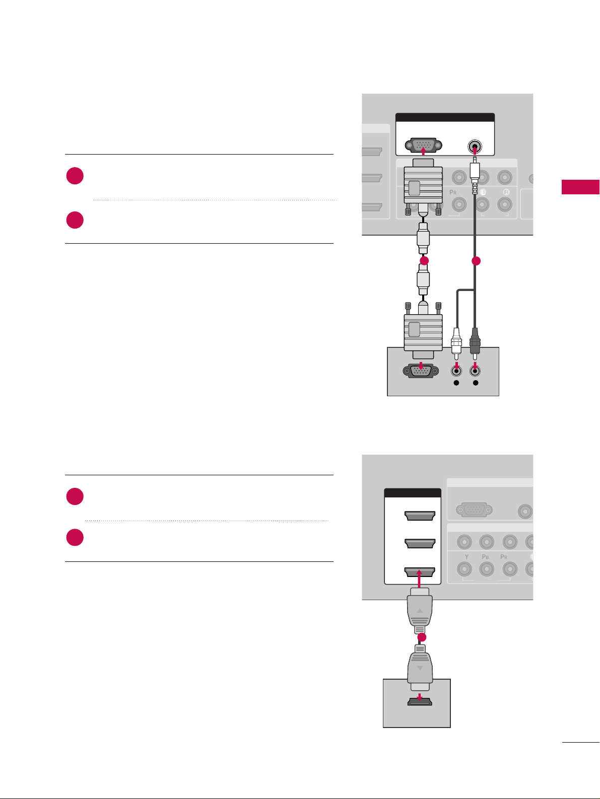
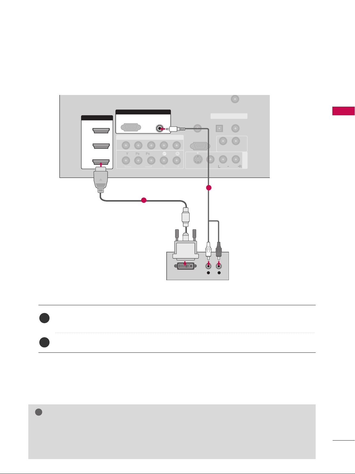
When connecting D-sub 15pin cable
COMPONENT IN
R
CO
1
2
R
(CON
VIDEO
AUDIO
( )
S
( )
RGB IN
AUDIO
(RGB/DVI)
RGB(PC)
L R
RGB OUTPUT
RGB IN
COMPONENT IN
AUDIO
(RGB/DV
RGB(PC)
1
2
VIDEO
( )
HDMI/DVI IN
1
2
3
HDMI-DTV OUTPUT
Connect the RGB output of the digital set-top box to
the
RRGGBB ((PPCC
))
jack on the set.
Connect the audio outputs of the set-top box to the
AAUUDDIIOO ((RRGGBB//DDVVII
))
jack on the set.
1. How to connect
2. How to use
■
Turn on the PC and the set.
■
Select
RRGGBB--PPCC
input source with using the
IINNPPUUTT
button
on the remote control.
When connecting HDMI cable
Connect the digital set-top box to
HH DDMMII//DDVVII IINN11
,
22
or
33
jack on the set.
No separated audio connection is necessary.
HDMI supports both audio and video.
1. How to connect
2. How to use
■
Turn on the digital set-top box.
(
Refer to the owner’s manual for the digital set-top box.
)
■
Select
HHDDMMII11,HHDDMMII22 orHHDDMMII33
input source with using
the
IINNPPUUTT
button on the remote control.
■
If the digital set-top box player does not support Auto HDMI,
you need to set the output resolution appropriately.
2
1
2
1
1
2
1
Page 2
EXTERNAL EQUIPMENT SETUP
22
EXTERNAL EQUIPMENT SETUP
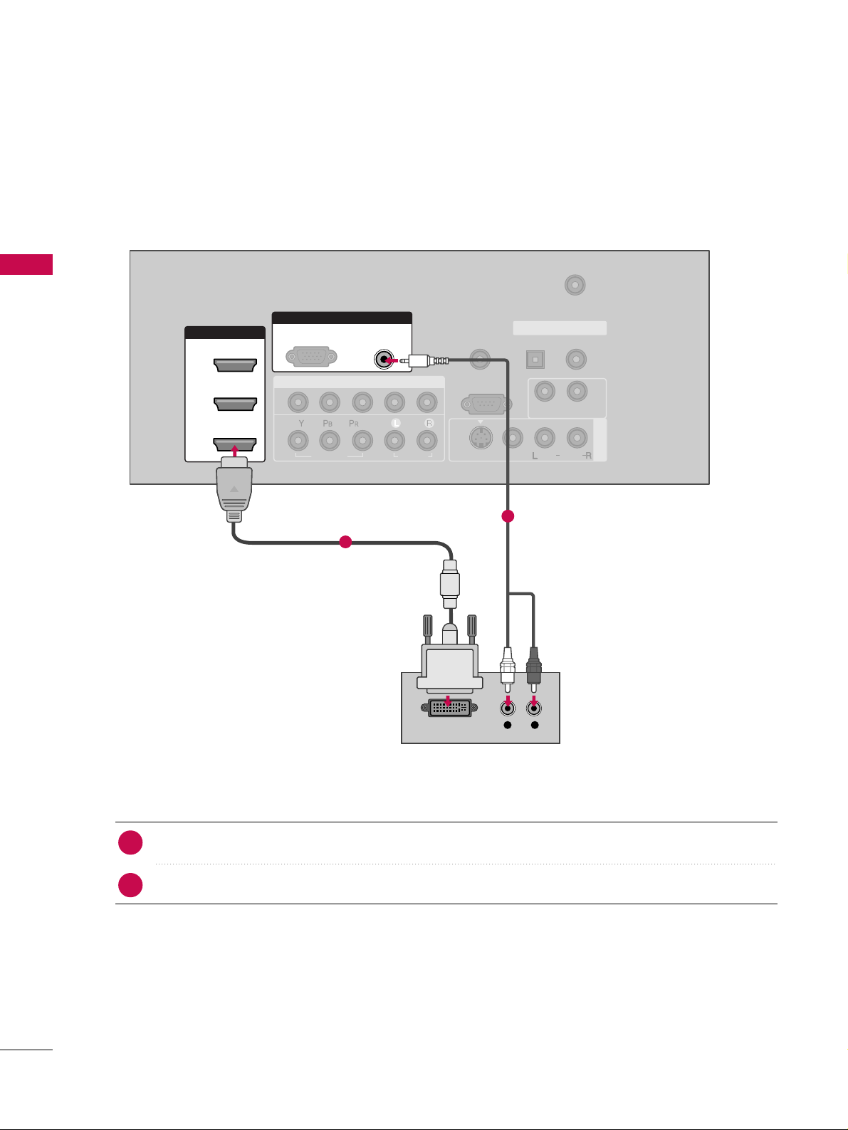
When connecting HDMI to DVI cable
( )
COMPONENT IN
AV IN 1
REMOTE
CONTROL IN
ANTENNA/
CABLE IN
1
2
RS-232C IN
(CONTROL & SERVICE)
VIDEO
AUDIO
AUDIO OUT
OPTICAL COAXIAL
DIGITAL AUDIO OUT
VIDEO
MONO
( )
AUDIO
S-VIDEO
HDMI/DVI IN
1
2
3
RGB IN
AUDIO
(RGB/DVI)
L R
DVI-DTV OUTPUT
RGB(PC)
Connect the DVI output of the digital set-top box to the
HH DDMMII//DDVVII IINN 11, 22
or
33
jack on the set.
Connect the audio output of the digital set-top box to the
AAUUDDIIOO((RRGGBB//DDVVII
))
jack on the set.
1. How to connect
■
Turn on the digital set-top box. (Refer to the owner’s manual for the digital set-top box.
)
■
Select
HHDDMMII11,HHDDMMII22 orHHDDMMII33
input source with using the
IINNPPUUTT
button on the remote control.
2. How to use
2
1
1
2
Page 3
EXTERNAL EQUIPMENT SETUP
23
DVD SETUP
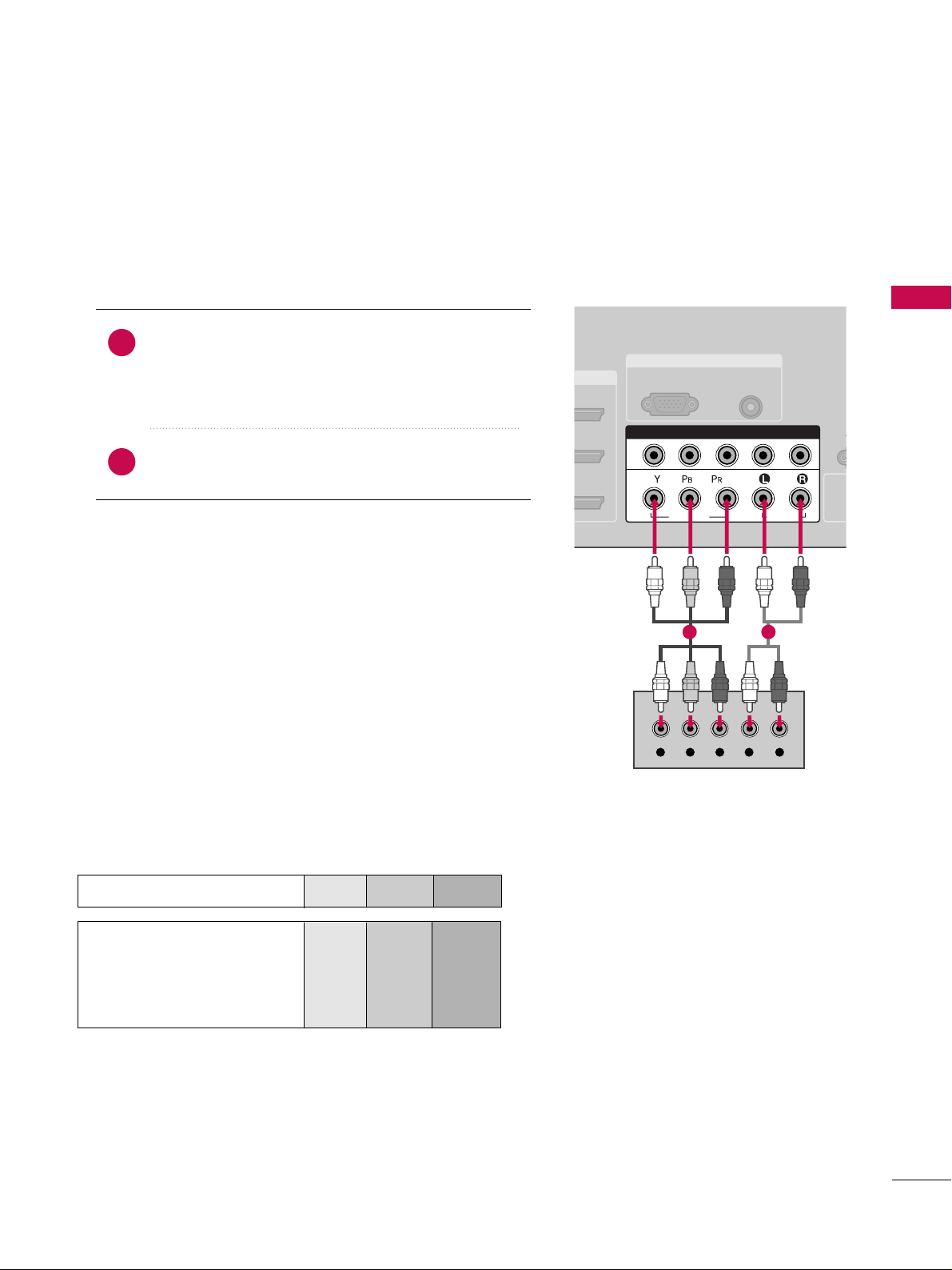
When connecting Component cable
Component Input ports
To get better picture quality, connect a DVD player to the component input ports as shown below.
Component ports on the TV
YPBP
R
Video output ports
on DVD player
Y
Y
Y
Y
P
B
B-Y
Cb
Pb
P
R
R-Y
Cr
Pr
Connect the video outputs (Y, P
B, P
R
)
of the DVD to the
CCOO MMPPOO NNEENNTT IINN VVIIDDEEOO11
jacks on the set.
Match the jack colors
(
Y = green, P
B = blue, and P
R = red
)
.
Connect the audio outputs of the DVD to the
CCOO MMPPOO NNEENNTT IINN AAUUDD II OO11
jacks on the set.
1. How to connect
2. How to use
■
Turn on the DVD player, insert a DVD.
■
Select
CCOOMMPPOONNEENNTT 11
input source by using the
IINN PPUUTT
button on the remote control.
■
If connected to
CCOO MMPPOONN EENN TT II NN 22
input, select
CCoomm ppoonneenntt 22
input source.
■
Refer to the DVD player's manual for operating instructions.
2
1
RGB IN
AUDIO
(RGB/DVI)
RGB(PC)
R
CO
R
(CONT
( )
S-
COMPONENT IN
1
2
VIDEO
AUDIO
Y L RPB PR
1 2
Page 4
EXTERNAL EQUIPMENT SETUP
24
EXTERNAL EQUIPMENT SETUP
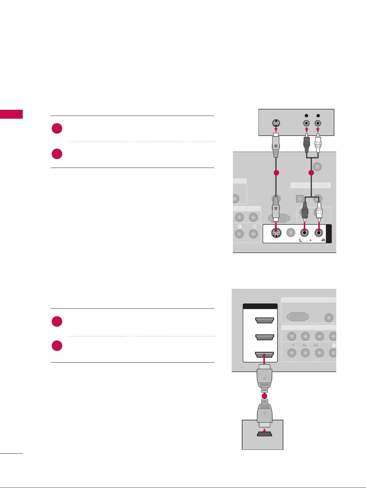
When connecting with an S-Video cable
Connect the S-VIDEO output of the DVD to the
SS --VV IIDD EEOO
input on the set.
Connect the audio outputs of the DVD to the
AAUU DD II OO
input jacks on the set.
1. How to connect
2. How to use
■
Turn on the DVD player, insert a DVD.
■
Select
AAVV11
input source by using the
IINN PPUUTT
button on the
remote control.
■
If connected to
AAVV IINN 22
, select
AAVV22
input source.
■
Refer to the DVD player's manual for operating instructions.
When connecting HDMI cable
Connect the HDMI output of the DVD to the
HH DDMMII// DDVVII II NN 11, 22
, or 33jack on the set.
No separated audio connection is necessary.
HDMI supports both audio and video.
1. How to connect
2. How to use
■
Select
HHDDMMII11,HHDDMMII22
,or
HHDDMMII33
input source by using
the
IINN PPUUTT
button on the remote control.
■
Refer to the DVD player's manual for operating instructions.
■
If the DVD does not support Auto HDMI, you need to set
the output resolution appropriately.
2
1
2
1
( )
B/DVI)
REMOTE
CONTROL IN
ANTENNA/
CABLE IN
RS-232C IN
(CONTROL & SERVICE)
AUDIO
AUDIO OUT
OPTICAL COAXIAL
DIGITAL AUDIO OUT
MONO
( )
AUDIO
S-VIDEO
AV IN 1
VIDEO
L R
S-VIDEO
AUDIO
1
2
RGB IN
COMPONENT IN
AUDIO
(RGB/DVI
RGB(PC)
1
2
VIDEO
A
( )
HDMI/DVI IN
1
2
3
HDMI-DVD OUTPUT
1
Page 5
EXTERNAL EQUIPMENT SETUP
25
VCR SETUP
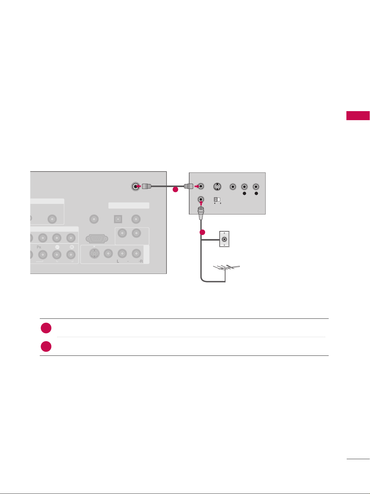
When connecting with an antenna
■
To avoid picture noise (interference), leave an adequate distance between the VCR and TV.
■
Use the ISM feature in the Option menu to avoid having a fixed image remain on the screen for a long period
of time
(Only
Plasma TV model
)
. If the 4:3 picture format is used; the fixed images on the sides of the
screen may remain visible on the screen. This phenomenon is common to all manufactures and in consequence the manufactures warranty does not cover the product bearing this phenomenon.
Connect the RF antenna out socket of the VCR to the
AANNTTEENNNN AA // CCAA BB LLEE II NN
socket on the set.
Connect the antenna cable to the RF antenna in socket of the VCR.
1. How to connect
■
Set VCR output switch to 3 or 4 and then tune TV to the same channel number.
■
Insert a video tape into the VCR and press PLAY on the VCR. (Refer to the VCR owner’s manual.
)
2. How to use
2
1
L R
S-VIDEO VIDEO
OUTPUT
SWITCH
ANT IN
ANT OUT
AV IN 1
AUDIO
(RGB/DVI)
REMOTE
CONTROL IN
ANTENNA/
CABLE IN
RS-232C IN
(CONTROL & SERVICE)
AUDIO
AUDIO OUT
OPTICAL COAXIAL
DIGITAL AUDIO OUT
VIDEO
MONO
( )
AUDIO
S-VIDEO
( )
Wall Jack
Antenna
1
2
Page 6
EXTERNAL EQUIPMENT SETUP
26
EXTERNAL EQUIPMENT SETUP
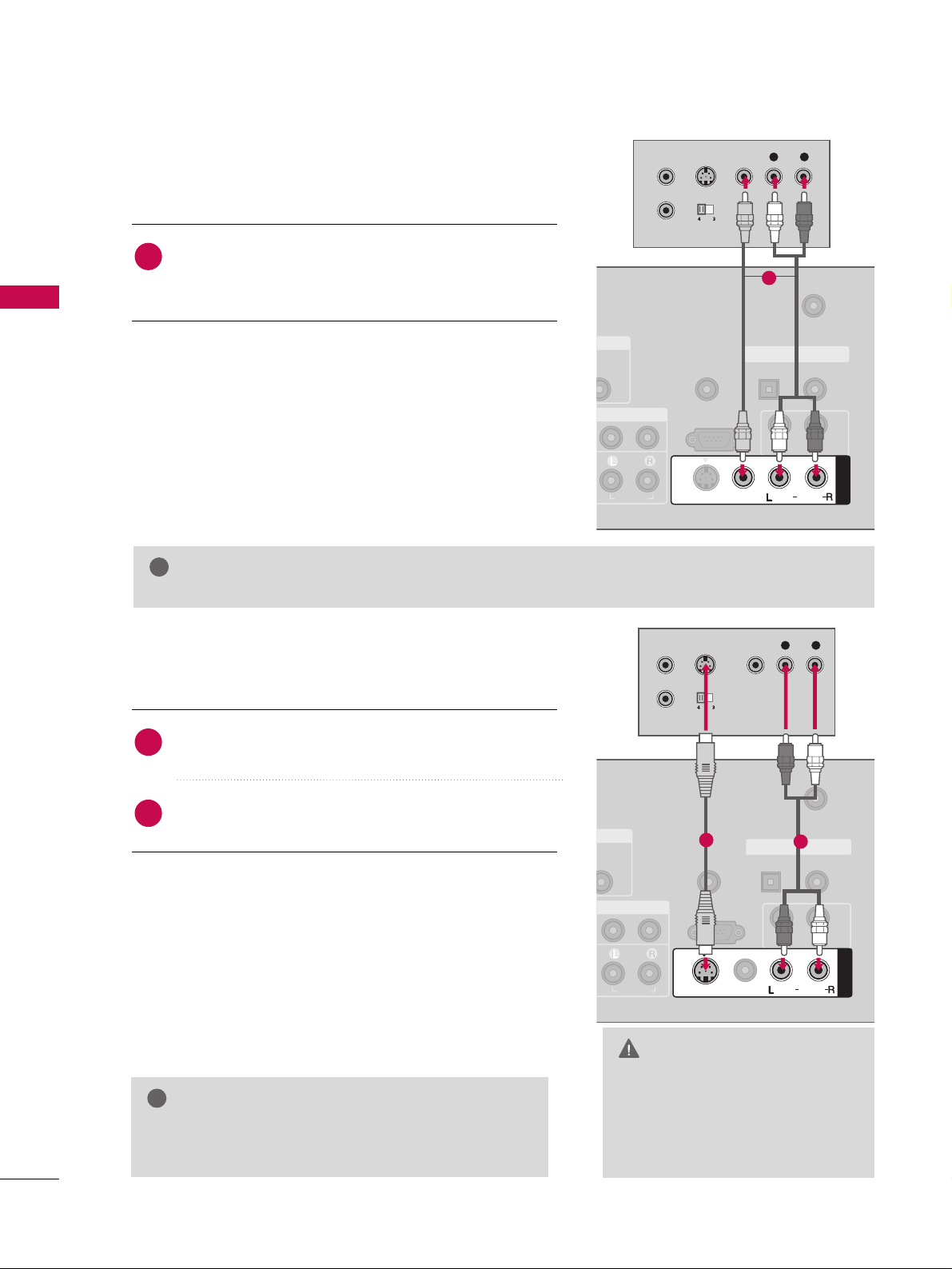
GG
Do not connect to both Video
and S-Video at the same time. In
the event that you connect both
Video and the S-Video cables,
only the S-Video will work.
CAUTION
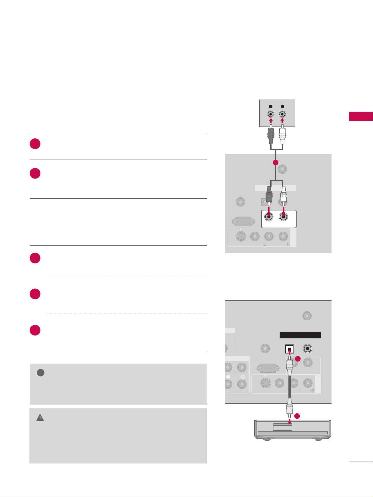
When connecting with a RCA cable
GG
The picture quality is improved: compared to normal
composite (RCA cable) input.
NOTE
!
Connect the
AAUU DD II OO/VVIIDDEEOO
jacks between TV and
VCR. Match the jack colors (Video = yellow, Audio Left
= white, and Audio Right = red)
1. How to connect
2. How to use
■
Insert a video tape into the VCR and press PLAY on the
VCR. (Refer to the VCR owner’s manual.
)
■
Select
AAVV11
input source by using the
IINN PPUUTT
button on
the remote control.
■
If connected to
AAVV IINN 22
, select
AAVV22
input source.
When connecting with an S-Video cable
Connect the S-VIDEO output of the VCR to the
SS --VV IIDD EEOO
input on the set.
Connect the audio outputs of the VCR to the
AAUU DD II OO
input jacks on the set.
1. How to connect
2. How to use
■
Insert a video tape into the VCR and press PLAY on the VCR.
(
Refer to the VCR owner’s manual.
)
■
Select
AAVV11
input source by using the
IINN PPUUTT
button on the
remote control.
■
If connected to
AAVV IINN 22
, select
AAVV22
input source.
1
2
1
GG
If you have a mono VCR, connect the audio cable from the VCR to the
AAUU DD II OO
LL// MM OONNOO
jack of the set.
NOTE
!
REMOTE
CONTROL IN
ANTENNA/
CABLE IN
RS-232C IN
(CONTROL & SERVICE)
AUDIO
AUDIO OUT
OPTICAL COAXIAL
DIGITAL AUDIO OUT
AV IN 1
VIDEO
MONO
( )
AUDIO
L R
S-VIDEO VIDEO
OUTPUT
SWITCH
ANT IN
ANT OUT
S-VIDEO
1
( )
(
)
REMOTE
CONTROL IN
ANTENNA/
CABLE IN
RS-232C IN
(CONTROL & SERVICE)
AUDIO
AUDIO OUT
OPTICAL COAXIAL
DIGITAL AUDIO OUT
AV IN 1
VIDEO
MONO
( )
AUDIO
S-VIDEO
L R
S-VIDEO VIDEO
OUTPUT
SWITCH
ANT IN
ANT OUT
1
2
Page 7
EXTERNAL EQUIPMENT SETUP
27
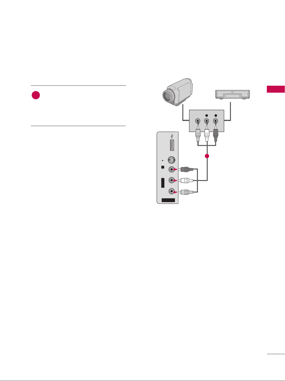
OTHER A/V SOURCE SETUP
Camcorder
Video Game Set
Connect the
AAUUDDIIOO/VVIIDDEEOO
jacks
between TV and external equipment.
Match the jack colors
.
(
Video = yellow, Audio Left = white, and
Audio Right = red
)
1. How to connect
2. How to use
■
Select
AAVV22
input source by using the
IINN PPUUTT
button on the remote control.
■
If connected to
AAVV IINN 11
input, select
AAVV11
input source.
■
Operate the corresponding external equipment.
1
1
USB IN
S-VIDEO
R
AUDIO
L/MONO
VIDEO
AV IN 2
VIDEO
L R
Page 8
EXTERNAL EQUIPMENT SETUP
28
PC SETUP
EXTERNAL EQUIPMENT SETUP
This TV provides Plug and Play capability, meaning that the PC adjusts automatically to the TV's settings.
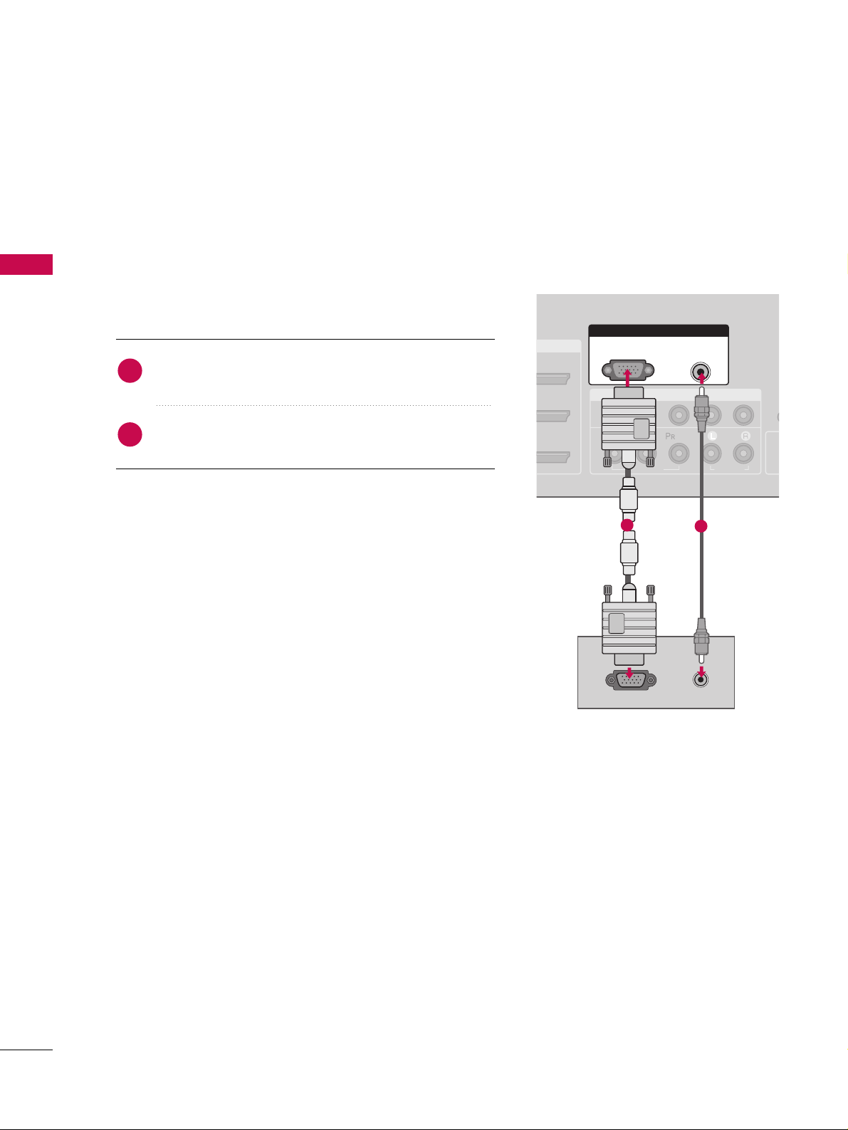
When connecting D-sub 15 pin cable
Connect the RGB output of the PC to the
RRGGBB ((PP CC
))
jack on the set.
Connect the PC audio output to the
AAUU DD II OO
((
RRGG BB//DD VV II
))
jack on the set.
1. How to connect
2. How to use
■
Turn on the PC and the TV.
■
Select
RRGG BB--PPCC
input source by using the
IINN PPUUTT
button
on the remote control.
2
1
I/DVI IN
COMPONENT IN
CO
1
2
(CO
VIDEO
AUDIO
( )
RGB IN
AUDIO
(RGB/DVI)
RGB(PC)
RGB OUTPUT AUDIO
1
2
Page 9
EXTERNAL EQUIPMENT SETUP
29
When connecting HDMI to DVI cable
Connect the DVI output of the PC to the
HHDDMMII//DDVVII IINN11, 22
or
33
jack on the set.
(Use the HDMI to DVI cable)
Connect the PC audio output to the
AAUUDDIIOO ((RRGGBB//DDVVII
))
jack on the set.
1. How to connect
2. How to use
■
Turn on the PC and the TV.
■
Select
HHDDMMII11,HHDDMMII22 orHHDDMMII33
input source by using the
IINN PPUUTT
button on the remote control.
2
1
( )
COMPONENT IN
AV IN 1
REMOTE
CONTROL IN
ANTENNA/
CABLE IN
1
2
RS-232C IN
(CONTROL & SERVICE)
VIDEO
AUDIO
AUDIO OUT
OPTICAL COAXIAL
DIGITAL AUDIO OUT
VIDEO
MONO
( )
AUDIO
S-VIDEO
HDMI/DVI IN
1
2
3
RGB IN
AUDIO
(RGB/DVI)
L R
DVI-PC OUTPUT
RGB(PC)
1
2
GG
If the PC has a DVI output and no HDMI output, a separated audio connection is necessary.
GG
If the PC does not support Auto DVI, you need to set the output resolution appropriately.
NOTE
!
Page 10

EXTERNAL EQUIPMENT SETUP
30
EXTERNAL EQUIPMENT SETUP
GG
To get the the best picture quality, adjust the PC
graphics card to 1920x1080, 60Hz.
GG
Depending on the graphics card, DOS mode may
not work if a HDMI to DVI Cable is in use.
GG
Check the image on your TV. There may be noise
associated with the resolution, vertical pattern,
contrast or brightness in PC mode. If noise is
present, change the PC output to another resolution, change the refresh rate to another rate or
adjust the brightness and contrast on the VIDEO
menu until the picture is clear. If the refresh rate of
the PC graphic card can not be changed, change
the PC graphic card or consult the manufacturer of
the PC graphic card.
GG
Avoid keeping a fixed image on the screen for a
long period of time. The fixed image may become
permanently imprinted on the screen.
GG
The synchronization input form for Horizontal and
Vertical frequencies is separate.
NOTES
!
Page 11

EXTERNAL EQUIPMENT SETUP
31
Supported Display Specifications
RGB/HDMI-PC
Horizontal Vertical
Frequency(KHz)Frequency(Hz
)
31.468 70.09
31.469 70.08
31.469 59.94
37.861 72.80
37.500 75.00
35.156 56.25
37.879 60.31
48.077 72.18
46.875 75.00
48.363 60.00
56.476 70.06
60.023 75.02
47.776 59.870
60.289 74.893
47.712 60.015
63.981 60.020
79.976 75.025
75.00 60.00
67.50 60.00
Resolution
720x400
1360x768
640x350
* RGB-PC mode only: 1280x768(H-60.289, V-74.893)
640x480
800x600
1024x768
HDMI-DTV
Horizontal Vertical
Frequency(KHz)Frequency(Hz
)
31.47 60.00
31.47 59.94
45.00 60.00
44.96 59.94
33.75 60.00
33.72 59.94
67.50 60.00
67.432 59.939
27.00 24.00
26.97 23.94
33.75 30.00
33.71 29.97
Resolution
720x480
1280x720
1920x1080
1280x1024
1600x1200
1920x1080
1280x768
1280x768
Y, CB /PB,CR /P
R
Horizontal Vertical
Frequency(KHz)Frequency(Hz
)
15.73 60.00
15.73 59.94
31.47 59.94
31.47 60.00
45.00 60.00
44.96 59.94
33.75 60.00
37.72 59.94
67.50 60.00
67.432 59.939
27.00 24.00
26.97 23.94
33.75 30.00
33.71 29.97
Resolution
1280x720
1920x1080
720x480
Page 12
EXTERNAL EQUIPMENT SETUP
32
EXTERNAL EQUIPMENT SETUP
Screen Setup for PC mode
Overview
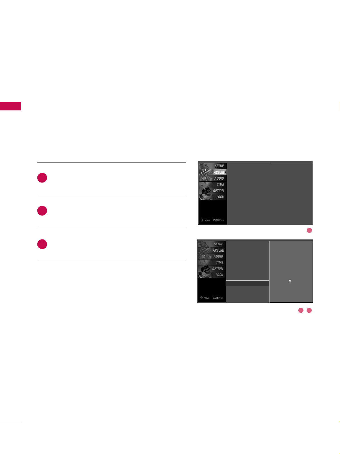
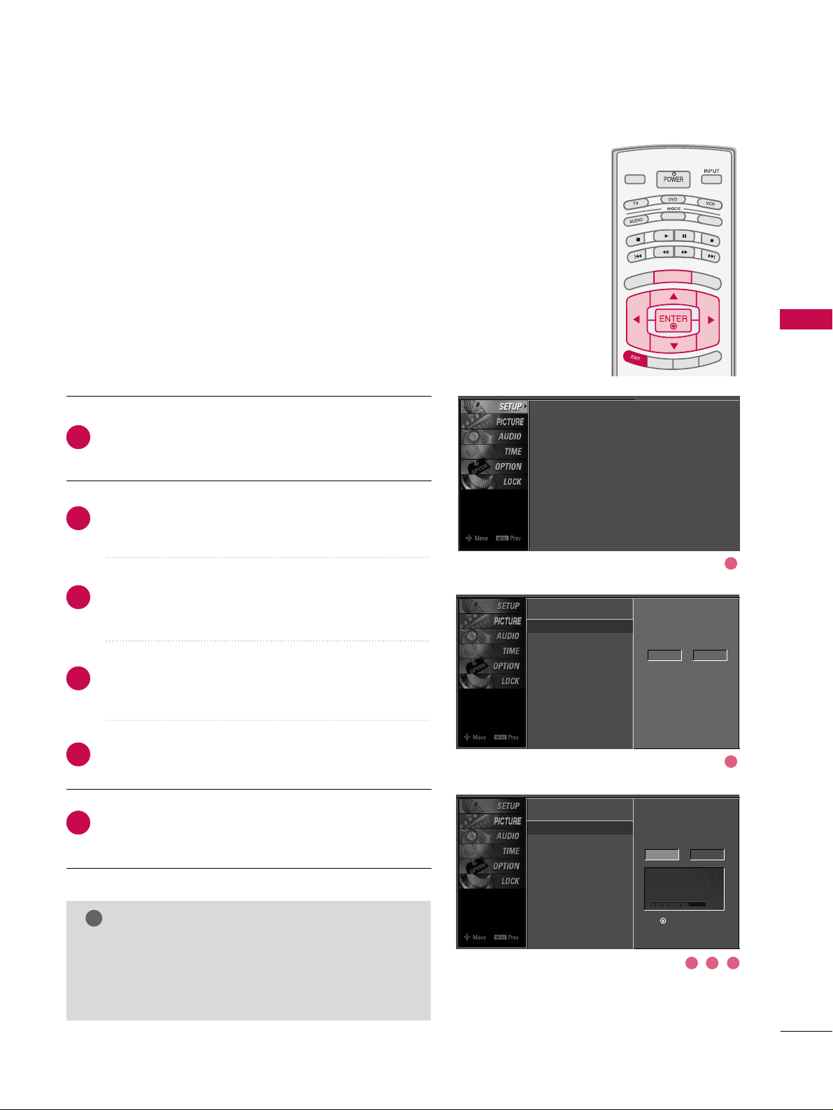
Press the
MMEENNUU
button and then use DDor EEbutton
to select the
PP II CCTT UURR EE
menu.
Press the GGbutton and then use DDor EEbutton to
select
SS ccrr eeeenn
.
Press the
GG
button to enter the screen adjustment
menu.
When the RGB input, of the set is connected to a PC
Output, Select RGB-PC with using the
IINNPPUUTT
button on the
remote control.
When you change the resolution, select the proper resolution
in present input to see the best picture appearance.
2
3
1
Picture Mode
Color Temperature
XD
Advanced
Aspect Ratio
Picture Reset
Screen
G
Selection ( Gor ) leads you to the
screen adjustment menu.
Picture Mode : User1
Color Temperature : Cool
XD
Advanced
Aspect Ratio : 16:9
Picture Reset
Screen
1
2 3
Page 13
EXTERNAL EQUIPMENT SETUP
33
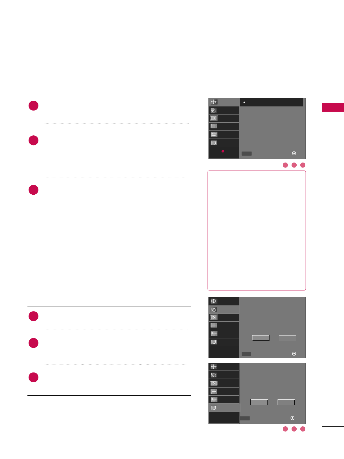
RReessoolluuttiioonn
XGA(1024, 1280, 1360) isn’t
distinguished because of having
the same H/V Sync Time.
This function is you to select the
Default Sync Time.
PPoossiittiioonn
This function is to adjust picture
to left/right and up/down as you
prefer.
SSiizzee
This function is to minimize any
vertical bars or stripes visible on
the screen background. And the
horizontal screen size will also
change.
PPhhaassee
This function allows you to
remove any horizontal noise and
clear or sharpen the image of characters.
Use DDor EEbutton to select
RReessoolluuttiioonn, PPoossiittiioonn, SSiizzee
,
or
PPhhaassee
.
Press the
EENNTTEERR
button and then use
DD EE
FF GG
button to make appropriate adjustments.
■
The
PPhhaassee
adjustment range is
--1166~++1166
.
■
The
SSiizzee
adjustment range is
--3300~++3300
.
Press the
EENNTTEERR
button.
Adjustment for screen Resolution, Position, Size, and Phase
Use DDor EEbutton to select
RReesseett
or
AAuuttoo
.
Press the
EENNTTEERR
button and then use
FF
or GGbutton to
select
YYeess
.
Press the
EENNTTEERR
button.
Auto Configuration and Initializing (Reset to
original factory values)
2
3
1
2
3
1
To initialize the adjusted values.
2 31
2 31
Initialize Settings.
Yes No
Select
Prev
OK
FF GG
MENU
Resolution
Auto Config.
Position
Size
Phase
Reset
Resolution
Auto Config.
Position
Size
Phase
Reset
Select
Prev
Ok
DD
EE
MENU
1024 x 768
1280 x 768
1360 x 768
Resolution
Auto Config.
Position
Size
Phase
Reset
Auto config.
Yes
No
Select
Prev
OK
FF GG
MENU
Page 14
EXTERNAL EQUIPMENT SETUP
34
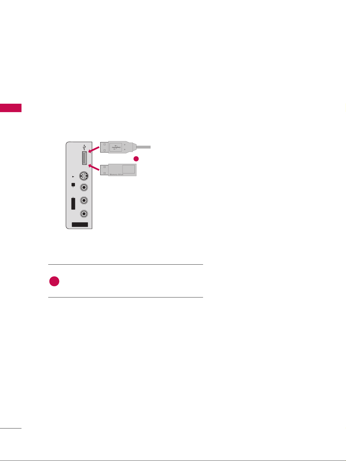
USB IN SETUP
EXTERNAL EQUIPMENT SETUP
The TV has a special signal output capability which allows you to hook up the second TV or monitor.
AV IN 2
L/MONO
R
AUDIO
VIDEO
S-VIDEO
USB IN
Connect the USB device to the
UU SSBB II NN
(or
UU SS BB
) jack
on the side of TV.
1. How to connect
1
2. How to use
■
After connecting the
UU SSBB II NN
(or
UU SS BB
) jack, you use the
function. (
GG
pp..4488
)
MEDIAMEDIA
HOST HOST
1
or
Page 15
EXTERNAL EQUIPMENT SETUP
35
AUDIO OUT SETUP
Send the TV’s audio to external audio equipment via the Digital Audio Output (Optical)port.
GG
When connecting with external audio equipments, such as amplifiers or speakers, please turn the TV speakers off. (
GG
pp..7711
)
NOTE
!
GG
Do not look into the optical output port. Looking at the
laser beam may damage your vision.
GG
Block the SPDIF out(optical/coaxial) about the contents
with ACP(Audio Copy Protection) function.
CAUTION
Connect one end of the optical or coaxial cable to the TV’s
OO PPTTIICCAALL
or
CCOOAAXXIIAALL
port of
DDIIGGIITTAALL AAUUDDIIOO OOUUTT
.
Connect the other end of the optical or coaxial cable to the
digital audio input on the audio equipment.
Set the “TV Speaker option - Off ” in the AUDIO menu. (
GG
pp..7711
). See the external audio equipment instruction manual
for operation.
1. How to connect
2
3
1
Connect audio outputs to the TV’s
AAUUDDIIOO OOUUTT
jacks.
Set the “TV Speaker option - Off” in the AUDIO menu.
(
GG
pp..7711
). See the external audio equipment instruction
manual for operation.
1. How to connect
2
1
Analog
Digital
AV IN 1
REMOTE
CONTROL IN
ANTENNA/
CABLE IN
RS-232C IN
(CONTROL & SERVICE)
OPTICAL COAXIAL
DIGITAL AUDIO OUT
VIDEO
MONO
( )
AUDIO
S-VIDEO
AUDIO OUT
L R
AUDIO
1
( )
AV IN 1
REMOTE
CONTROL IN
ANTENNA/
CABLE IN
RS-232C IN
(CONTROL & SERVICE)
AUDIO
AUDIO OUT
VIDEO
MONO
( )
AUDIO
S-VIDEO
OPTICAL
DIGITAL AUDIO OUT
COAXIAL
1
2
Page 16
WATCHING TV / CHANNEL CONTROL
36
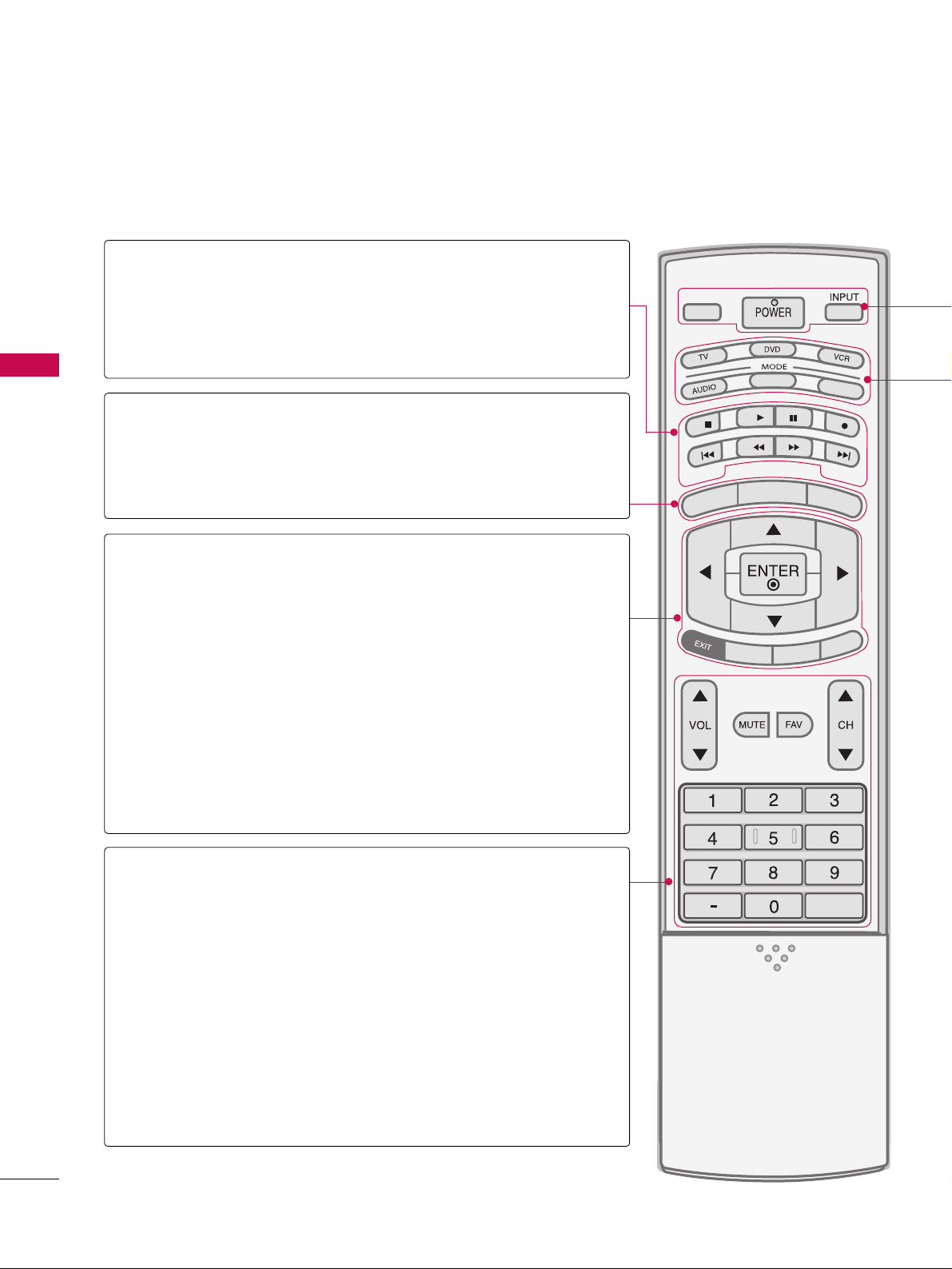
REMOTE CONTROL FUNCTIONS
WATCHING TV / CHANNEL CONTROL
When using the remote control, aim it at the remote control sensor on the TV.
APM
CC
AUTO DEMO
M/C EJECT
TV INPUTTV INPUT
STBSTB
MENU
BRIG
HT +
B
RIGHT -
TIMER
RATIO
SIMPLINK
BACKBACK
TV INPUT
STB
BACK
TV INPUT
STB
BACK
PICTURE
SOUND
SAP
CC
MARK
USB EJECT
MEDIA HOSTMEDIA HOST
MEDIA HOST
MEDIA HOST
MENU
BRIGHT +/-
THUMBSTICK
(Up/Down/Left
Right/ENTER)
EXIT
TIMER
RATIO
SIMPLINK
VOLUME UP
/DOWN
MUTE
FAV
CHANNEL
UP/DOWN
BACK
— (DASH)
■
Controls the mode.
■
Control video cassette recorders or DVD players.
Displays the main menu.
■
Adjust brightness on screen.
■
It turns to the default settings brightness by changing
mode source.
■
Navigate the on-screen menus and adjust the system
settings to your preference.
Clear all on-screen displays and return to TV viewing from
any menu.
Select the amount of time before your TV turns off automatically.
GG
pp..8822
Change the aspect ratio.
GG
pp..5555
See a list of AV devices connected to TV.
When you toggle this button, the SimpLink menu appears
at the screen.
Increase/decrease the sound level.
Switch the sound on or off.
GG
pp..3388
Scroll through the programmed Favorite channels.
GG
pp..4422
Select available channels.
Tune to the last channel viewed.
Used to enter a program number for multiple
program channels such as 2-1, 2-2, etc.
MEDIAMEDIA
HOST HOST
mode control
buttons
MEDIAMEDIAMEDIA
HOST HOST HOST
MEDIA
HOST
NUMBER button
VCR/DVD
buttons
Page 17

WATCHING TV / CHANNEL CONTROL
37
TV INPUT
STB
BACK
PICTURE
SOUND
SAP
CC
MARK
USB EJECT
MEDIA HOST
Inside the Sliding Cover
PICTURE
SOUND
SAP
CC
MARK
USB EJECT
Adjust the factory preset picture depend
on the viewing environment.
GG
pp.. 5566
Select the appropriate type of sound for
type of program.
GG
pp.. 6688
Select MTS sound: Mono, Stereo, and SAP
analog mode. Change the audio language
DTV mode.
GG
pp.. 7722
Select the Caption On/Off.
GG
pp..7755
Enter the selected functions.
GG
pp..5500
Remove the USB device.
GG
pp..3344
Installing Batteries
■
Open the battery compartment cover on the
back side and install the batteries matching correct polarity (+with +,-with -).
■
Install two 1.5V AA batteries. Don’t mix old or
used batteries with new ones.
■
Close cover.
■
Use a remote control up to 7 meters distance and 30
degree (left/right) within the receiving unit scope.
■
Dispose of used batteries in a recycle bin to preserve environment.
Remote control effective range
POWER
TV INPUT
INPUT
MODE
MEDIAMEDIAMEDIA
HOST HOST HOST
MEDIA
HOST
Turns your TV or any other programmed equipment on or off, depending on the mode.
In AV 1-2, Component 1-2, RGB-PC, HDMI1, HDMI2 and HDMI3 input sources, screen returns to
the last TV channel.
External input modes rotate in regular sequence: Antenna, Cable, AV1-2, Component 1-2, RGB-PC,
HDMI1, HDMI2, HDMI3 (Antenna, Cable, AV 1-2, Component 1-2, RGB-PC, HDMI1, HDMI2,
HDMI3 input sources are linked automatically, only if these are connected ).
Select the remote operating mode: TV, DVD, VCR, AUDIO, CABLE or STB.
* If the mode of another product is selected, a button on the remote control which is not used
for the selected product can control the TV.
Enter to the mode.
MEDIAMEDIA
HOST HOST
MARK
SOUND
USB EJECT
PICTURE
SAP
BACK
CC
LIVE TV
INPUT
MODE
D
-
A
Y
Y
A
+
D
LIVE TV
INPUT
MODE
D
-
A
Y
Y
A
+
D
Page 18

WATCHING TV / CHANNEL CONTROL
38
TURNING ON TV
WATCHING TV / CHANNEL CONTROL
NOTE
!
GG
If you intend to be away on vacation, disconnect the power plug from the wall power outlet.
First, connect power cord correctly.
At this moment, the TV switches to standby mode.
■
In standby mode to turn TV on, press the ,
IINNPPUUTT,CCHH ((
DD
or
EE
))
button on the TV or press the
PPOOWWEERR, IINNPPUUTT, TTVV IINNPPUUTT, CCHH((
DD
or
EE
)), NNuummbbeerr ((00~99))
button on the remote control.
Select the viewing source by using the
TTVV IINNPPUUTT, IINNPPUUTT
button on the
remote control.
■
This TV is programmed to remember which power state it was last set
to, even if the power cord is out.
When finished using the TV, press the
PPOOWWEERR
button on the remote
control. The TV reverts to standby mode.
TV INPUTTV INPUT
INPUT
TV INPUT
STB
PICTUREPICTUREPICTURE
SOUNDSOUND
SAPSAP
CCCC
MARKMARK
USB EJECTUSB EJECT
BACKBACK
MEDIA HOST
1
2
3
TV INPUT
STB
T
I
M
E
R
RAT
I
O
SIMPLINK
BACKBACK
TV INPUT
STB
BACK
TV INPUT
STB
BACK
TV INPUT
STB
BACK
MEDIA HOST
MEDIA HOST
MEDIA HOST
MEDIA HOST
Press the
CCHH ((
DD
or
EE
))
or
NNUUMMBBEERR
buttons to select a channel number.
1
VOLUME ADJUSTMENT
CHANNEL SELECTION
Press the
VVOOLL ((
DD
or
EE
))
button to adjust the volume.
If you want to switch the sound off, press the
MMUUTTEE
button.
You can cancel the Mute function by pressing the
MMUUTTEE
or
VVOOLL ((
DD
or
EE
))
button.
TV INPUT
STB
T
I
M
E
R
RAT
I
O
S
IMPLINK
TV INPUT
STB
TV INPUT
STB
TV INPUT
STB
TV INPUT
MEDIA HOST
MEDIA HOST
MEDIA HOST
MEDIA HOST
Adjust the volume to suit your personal preference.
1
2
3
Page 19
WATCHING TV / CHANNEL CONTROL
39
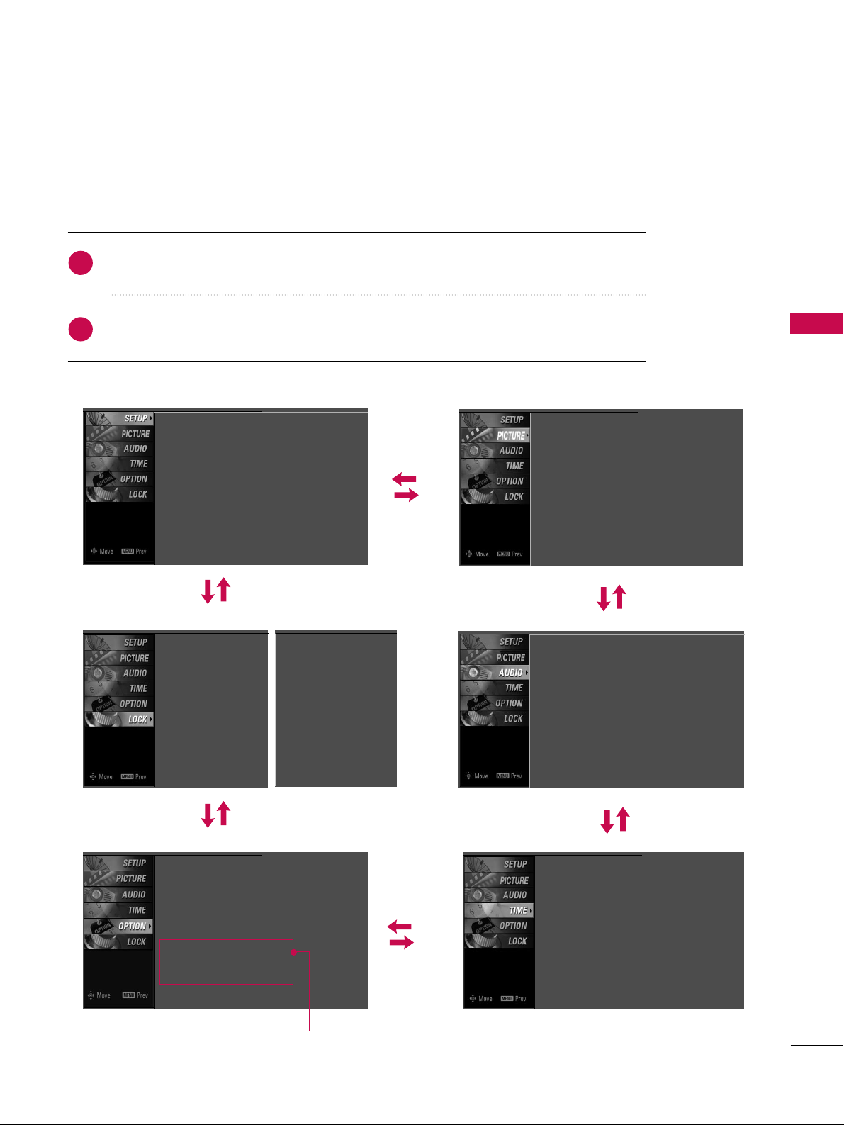
ON-SCREEN MENUS SELECTION
Press the
MMEENNUU
button and then use DDor EEbutton to select the each menu.
Press the
GG
button and then use
DD EE FF GG
button to display the available menus.
Your TV's OSD (On Screen Display)may differ slightly from what is shown in this manual.
2
1
SETUP
PICTURE
TIME
Auto Tuning
Manual Tuning
Channel Edit
AUDIO
Picture Mode : User1
Color Temperature : Cool
XD
Advanced
Aspect Ratio : 16:9
Picture Reset
Screen
Sound Mode : Standard
Auto Volume : On
Balance : 0
TV Speaker : On
Clock :
Oct 19, 2006, 03:44 AM
Off Time : Off
On Time : Off
Sleep Time : Off
Auto Sleep : Off
Language :
English
Input Label
SimpLink : Off
Key Lock : Off
Caption : Off
ISM Method : Orbiter
Low Power : Off
Front Display : Bright
Set ID : 1
Lock System : Off
Set Password
Block Channel
Movie Rating
TV Rating-Children
TV Rating-General
Input Block
OPTION
LOCK
Lock System : Off
Set Password
Block Channel
TV Rating-English
TV Rating-French
Input Block
For USA
For Canada
Only Plasma TV model
Page 20
WATCHING TV / CHANNEL CONTROL
40
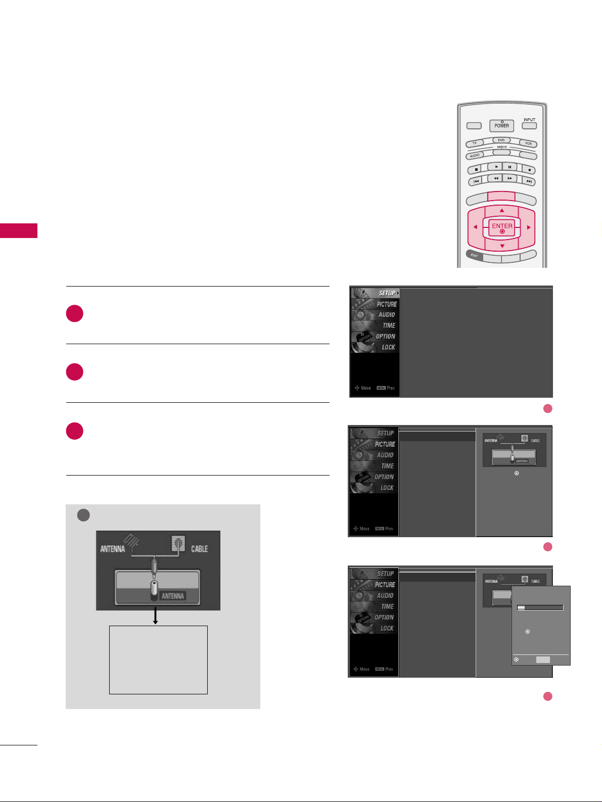
CHANNEL SETUP
WATCHING TV / CHANNEL CONTROL
Press the
MMEENNUU
button and then use DDor EEbutton
to select the
SS EETTUUPP
menu.
Press the GGbutton and then use DDor EEbutton to
select
AAuu ttoo TTuunniinngg
.
Press the
EENNTTEERR
button to begin the channel search.
Allow
AAuu ttoo TTuunniinngg
to complete the channel search
cycle for
AANNTTEENNNNAA
and
CCAABBLL EE
.
Automatically finds all channels available through antenna
or cable inputs, and stores them in memory on the channel
list.
Run Auto Tuning again after any Antenna/Cable connection
changes.
A password is required to gain access to Auto Tuning menu
if the Lock System is turned on.
2
3
1
TV INPUTTV INPUT
STBSTB
BRIG
HT +
BRI
G
H
T
-
T
I
M
E
R
R
A
T
I
O
S
IMPLINK
M
E
N
U
TV INPUT
STB
TV INPUT
STB
TV INPUT
STB
TV INPUT
STB
MEDIA HOSTMEDIA HOST
MEDIA HOST
MEDIA HOST
MEDIA HOST
MEDIA HOST
Auto Scan (Auto Tuning)
Auto Tuning
G
Manual Tuning
Channel Edit
Selection ( Gor ) leads you to
the Auto Tuning screen.
Auto Tuning
Manual Tuning
Channel Edit
Selection ( Gor ) leads
you to the Auto Tuning
screen.
NOTE
!
Analog TV antenna
Digital DTV antenna
Analog CATV cable
Digital CADTV cable
Processing Auto Tuning...
DTV Ch.23
Found Channel(s): 16
Press to stop the current
scan and start ANALOG
ANTENNA channel scan.
MENU Prev
Next
Auto Tuning
Manual Tuning
Channel Edit
1
2
3
Page 21
WATCHING TV / CHANNEL CONTROL
41
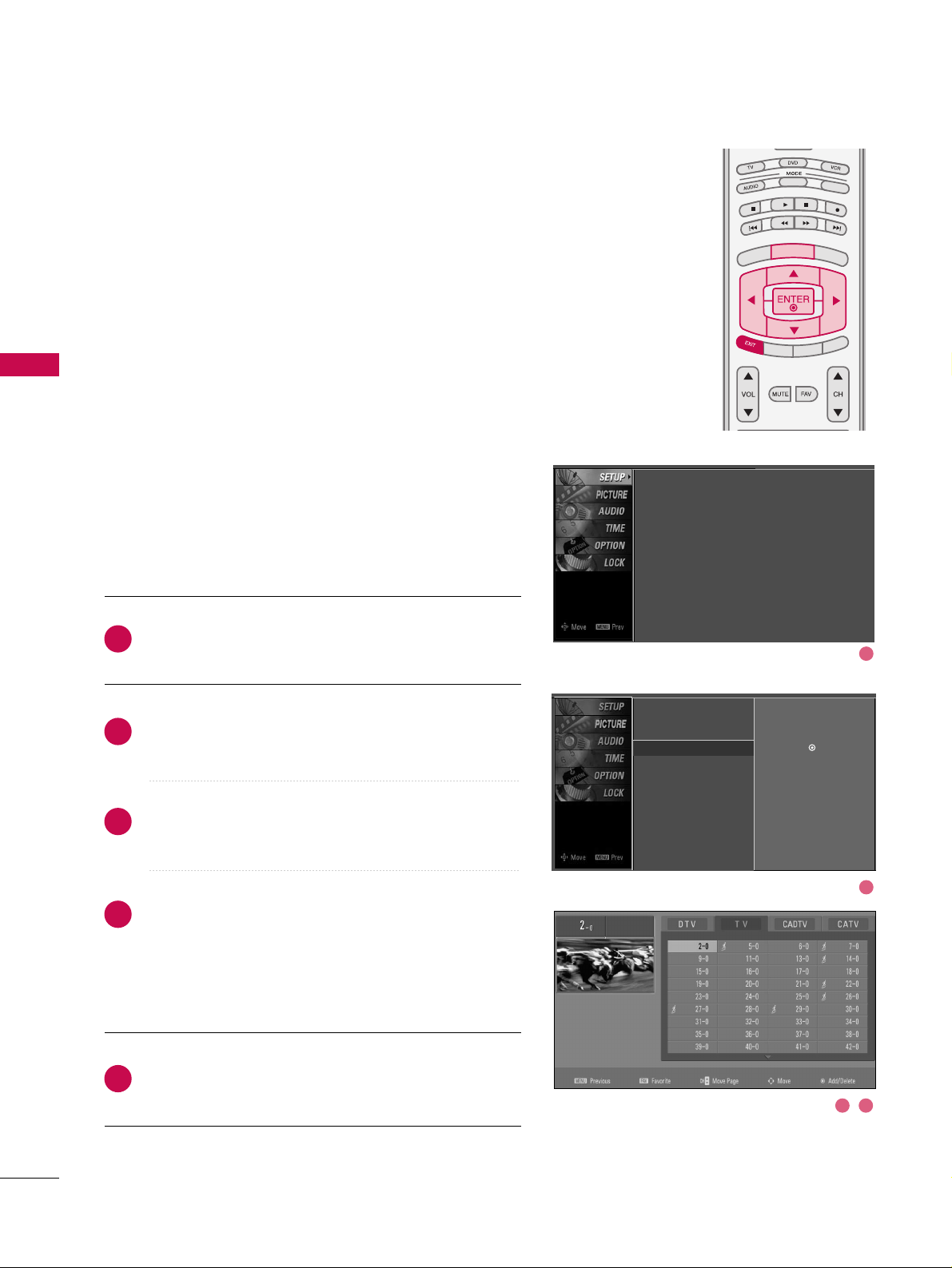
A password is required to gain access to Manual Tuning
menu if the Lock System is turned on.
If selecting DTV or CADTV input signal, you can view the
on-screen signal strength monitor to see the quality of the
signal being received.
Press the
MMEENNUU
button and then use
DD
or EEbutton
to select the
SSEETTUUPP
menu.
Press the
GG
button and then use DDor EEbutton to
select
MMaannuuaall TTuunniinngg
.
Press the
GG
button and then use DDor EEbutton to
select
TTVV, DD TT VV, CCAATTVV
, and
CCAADDTTVV
.
Press the GGbutton and then use DDor EEbutton to
select channel you want to add or delete.
Press the
EENNTTEERR
button to add or delete the channel.
Press
EEXXIITT
button to return to TV viewing or press
MMEENNUU
button to return to the previous menu.
TV INPUTTV INPUT
STBSTB
BRIGHT +
BRI
G
H
T
-
T
I
M
E
R
R
A
T
I
O
S
I
M
P
LINK
M
E
N
U
TV INPUT
STB
TV INPUT
STB
TV INPUT
STB
TV INPUT
STB
MEDIA HOSTMEDIA HOST
MEDIA HOST
MEDIA HOST
MEDIA HOST
MEDIA HOST
2
1
4
3
6
5
NOTE
!
GG
This digital channel number is a physical channel
number, which is different from the normal channel
number shown in Channel Edit.
Add/Delete Channel (Manual Tuning)
Auto Tuning
Manual Tuning
G
Channel Edit
Select channel type and
RF-channel number.
DTV 2
Auto Tuning
Manual Tuning
Channel Edit
Select channel type and
RF-channel number.
DTV
GG
12
Press to delete the channel.
DTV 12-0
DD
EE
Bad Normal Good
Auto Tuning
Manual Tuning
Channel Edit
1
2
3 4 5
Page 22
WATCHING TV / CHANNEL CONTROL
42
WATCHING TV / CHANNEL CONTROL
From the default channel list created from the Auto Tuning
channel search, you can create two different types of channel lists in memory: “custom list” and “favorite channel list”.
A custom list can be created by toggling each channel on or
off with ENTER button. The channels in the Custom List are
displayed in black and the channels deleted from the
Custom List are displayed in gray. Once a channel is highlighted you can add or delete the channel by referring to the
small window at the top-left corner of the screen.
You can create your own Favorite List. Use the
FFAA VV
button
on the remote control when a channel is highlighted and
then add or delete the channel to/from your Favorite List.
Press the
MMEENNUU
button and then use
DD
or EEbutton
to select the
SSEETTUUPP
menu.
Press the
GG
button and then use DDor EEbutton to
select
CChhaa nnnn eell EEddiitt
.
Press the
GG
button. You will now see a screen filled
with channel numbers and a preview picture.
Use
DD EE FF GG
button to select a channel and then
use the
EENNTTEERR
button to add or delete it. Press
FFAAVV
button to add the channel to the Favorite List. The
surfing icon will appear in front of that channel number.
Press
EEXXIITT
button to return to TV viewing or press
MMEENNUU
button to return to the previous menu.
TV INPUT
STBSTB
BRIG
HT +
BRI
G
H
T
-
T
I
M
E
R
R
A
T
I
O
S
I
M
P
LINK
M
E
N
U
TV INPUT
STB
TV INPUT
STB
TV INPUT
STB
TV INPUT
STB
MEDIA HOSTMEDIA HOST
MEDIA HOST
MEDIA HOST
MEDIA HOST
MEDIA HO
ST
2
1
4
3
5
Channel Editing
Auto Tuning
Manual Tuning
Channel Edit
G
Selection (Gor ) leads you to the
channel edit screen.
Auto Tuning
Manual Tuning
Channel Edit
1
2
3 4
Page 23
WATCHING TV / CHANNEL CONTROL
43
INPUT LIST
Press the
IINNPPUUTT
button to display external device that is
connected to the unit, on screen.
Press the
EE NN TT EE RR
button to change the input to the active
external device. Use the
DD
or EEbutton to select the input
source.
TV INPUT
STBSTB
M
E
N
U
BRI
GH
T +
B
RIG
H
T
-
T
I
M
E
R
RAT
I
O
S
I
MPLINK
INPUT
MEDIA HOSTMEDIA HOST
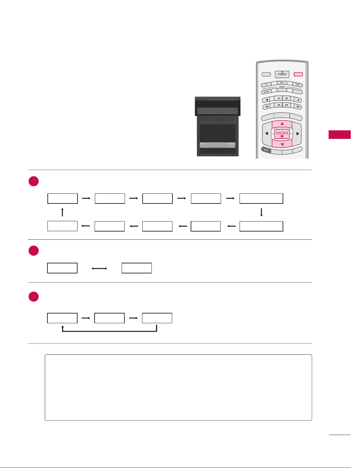
AAnntteennnnaa
: Select it when watching the DTV/TV.
CCaabbllee
: Select it when watching the CADTV/CATV.
AAVV 11,, AAVV 22
: Select it when watching the VCR or external equipment.
CCoommppoonneenntt 11--22
: Select it when using the DVD or the Digital set-top box depend on connector.
RRGGBB--PPCC
: Select it when using PC depend on connector.
HHDDMMII,, HHDDMMII22,, HHDDMMII33
: Select it when using DVD, PC or Digital set-top box depend on connector.
Antenna
Cable
AV 1
AV 2
Component1
EE
Input List
AV 2
AAnntteennnnaa CCaabbllee
If all external input sources are connected:
If no external input sources are not connected:
If there is any external input source connected:
(ex: When connected only to AV 2)
AAnntteennnnaa CCaabbllee
AAVV11
AAnntteennnnaa CCaabbllee AAVV22
AAVV22 CCoommppoonneenntt11
HHDDMMII22 HHDDMMII11 RRGGBB--PPCC CCoommppoonneenntt22
2
3
1
HHDDMMII33
Page 24
WATCHING TV / CHANNEL CONTROL
44
WATCHING TV / CHANNEL CONTROL
This operates only for the devices with the logo.
Please check the logo.
This allows you to control and play other AV devices
connected to the display through HDMI cable without
additional cables and settings.
TV INPUTTV INPUT
STBSTB
M
E
N
U
BRIGHT
+
B
RIG
HT
-
T
I
M
E
R
RAT
I
O
SIMP
LINK
MEDIA HOSTMEDIA HOST
TV INPUT
STB
MEDIA HOST
M
E
N
U
Connect the HDMI/DVI IN 1, 2 or 3 terminal of the TV
to the rear terminal (HDMI output) of the Simplink
device with the HDMI cable.
After connecting the HDMI jack for the home theater
with simplink function in the above method, connect
the DIGITAL AUDIO OUT OPTICAL on the back of the
TV to the DIGITAL AUDIO IN terminal on the back of
the simplink device with the Optical cable.
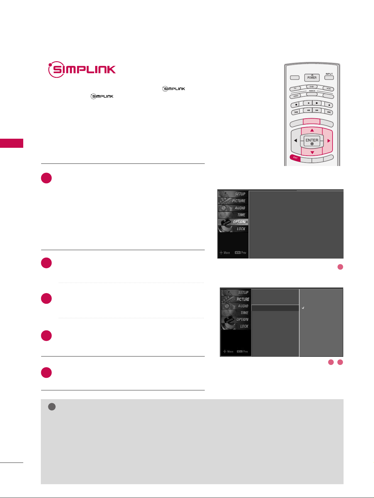
Press the
MMEENNUU
button and then use
DD
or EEbutton
to select the
OO PPTTIIOO NN
menu.
Press the
GG
button and then use DDor EEbutton to
select
SS iimmpp LLii nnkk
.
Press the
GG
button and then useDDor EEbutton to
select
OOnn
.
Press
EEXXIITT
button to return to TV viewing or press
MMEENNUU
button to return to the previous menu.
NOTE
!
GG
When operating the external device with SimpLink, press the TV button among the MODE button on the
remote control.
GG
When you switch the Input source with the INPUT button on the remote control, you can stop the opera-
tion of device worked by SimpLink.
GG
When you select or operate the media device with home theater function, the speaker automatically switch-
es to home theater speaker (HT speaker).
GG
When you execute ‘Photo List, Music List ’function during DVD playback included in home theater sup-
ported the SimpLink stops and the applicable function is executed after switching the input to TV.
SimpLink Preparations
2
3
4
5
1
2
3 4
Language : English
Input label
SimpLink : Off
Key Lock : Off
Caption : Off
ISM Method : Orbiter
Low Power : Off
Front Display : Bright
Set ID : 1
Language
Input Label
SimpLink
G
Key Lock
Caption
ISM Method
Low Power
Front Display
Set ID
Off
On
Page 25
WATCHING TV / CHANNEL CONTROL
45
TV INPUTTV INPUT
STBSTB
M
E
N
U
BR
I
G
H
T +
B
RIG
HT
-
T
I
M
E
R
R
A
T
I
O
S
I
MPLINK
MEDIA HOSTMEDIA HOST
SIMPL
INK
SIMPL
INK
■
DD iirr eecctt PPllaayy::
After connecting AV devices to TV, you can directly control the
devices and play media without additional settings.
■
SSeell eecctt AAVV ddeevviiccee::
Enables you to select one of AV devices connected to TV and
play it.
■
DD iiss cc ppll aayybbaacc kk::
Control connected AV devices by pressing the
,,
,, , ,
,
DD EE
FF GG
,
EENNTTEERR
buttons and buttons for play, stop, pause,
fast reverse, fast forward, chapter skip.
■
PPoowweerr ooffff aallll ddeevviicceess::
When you power off TV, all connected devices are turned off.
■
SSwwiittcc hh aauu ddiioo-- oouutt::
Offers an easy way to switch audio-out.
(A device, which is connected to TV through HDMI cable but does not support
SimpLink, does not provide this function)
SimpLink Menu
TTVV vviieeww iinngg
: Switch to the previous TV
channel regardless of the current mode.
DD II SSCC ppll aa yybb aa cckk
: Select and play discs.
When multiple discs are available, the titles
of discs are conveniently displayed at the
bottom of the screen.
VVCCRR ppll aayybb aa cckk
: Play and control the con-
nected VCR.
HH DDDD RReeccoo rrddiinnggss ppll aa yybb aacc kk
: Play and
control recordings stored in HDD.
AAuuddiioo OOuutt ttoo HH TT ss ppeeaakk eerr//AAuu ddiioo
OO uutt ttoo TTVV
: Select HT speaker or TV
speaker for Audio Out.
SimpLink Functions
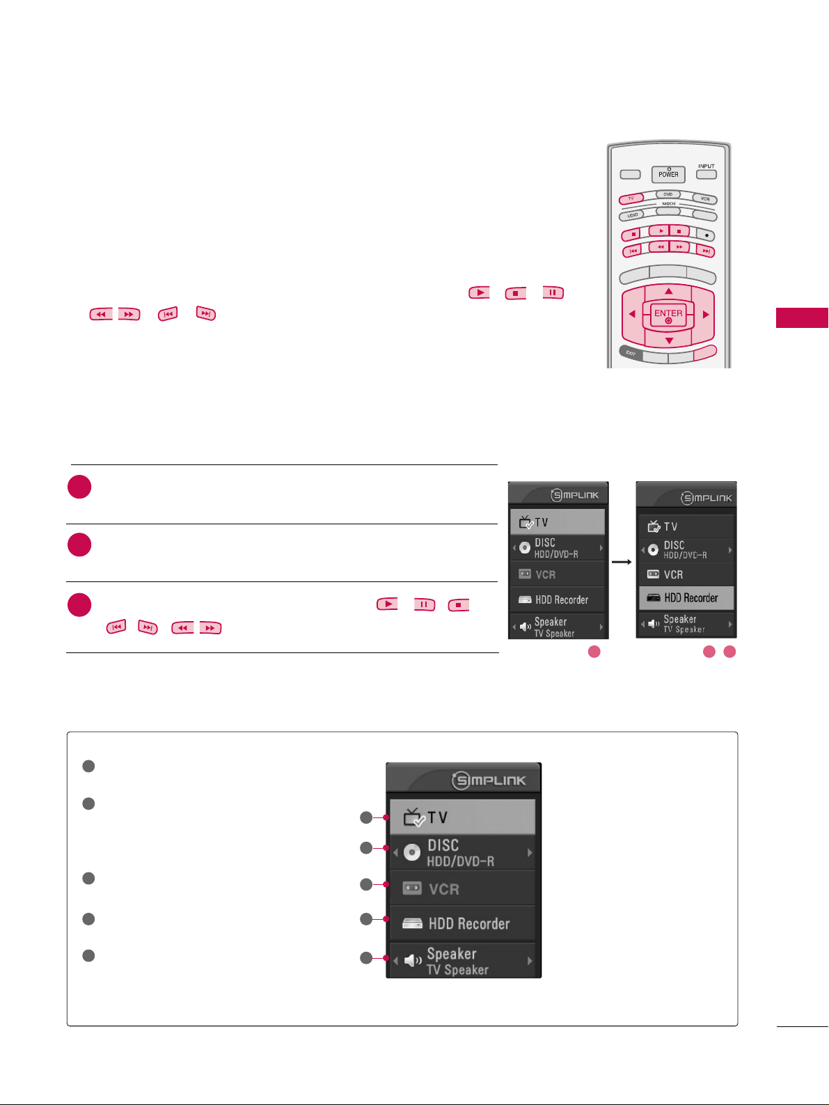
1
2
3
4
5
GG
Selected Device
GG
When no device is connected
(displayed in gray)
GG
When a device is connected
(displayed in bright color)
1
2
3
4
5
After selecting the
TTVV
button of the MODE on the remote control,
press the
SS II MM PPLL II NNKK
button.
Use
DD EE FF GG
button to select the desired device and then press
the
EENNTTEERR
button.
Control connected AV devices by pressing the
, , ,
,,,
,
DDEE
FF GG
,
EENNTTEERR
buttons.
2
1
3
21 3
Page 26

WATCHING TV / CHANNEL CONTROL
46
INPUT LABEL
WATCHING TV / CHANNEL CONTROL
Sets a label to each input source which is not in use when
you press the INPUT button.
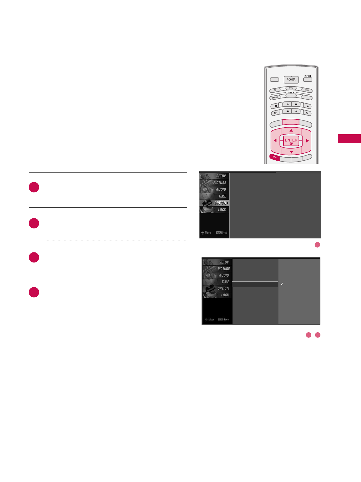
Press the
MMEENNUU
button and then use
DD
or EEbutton to
select the
OOPPTTIIOONN
menu.
Press the
GG
button and then useDDor EEbutton to
select
IInnppuutt LLaabbeell
.
Press the
GG
button and then useDDor EEbutton to
select the source: AV1, AV2, Component1,
Component2, RGB-PC, HDMI1, HDMI2 or HDMI3.
Press the
FF
or GGbutton to select the label.
Press
EEXXIITT
button to return to TV viewing or press
MMEENNUU
button to return to the previous menu.
2
3
4
5
1
TV INPUTTV INPUT
STBSTB
BR
IGHT +
BRI
G
H
T
-
T
I
M
E
R
R
A
T
I
O
S
I
M
P
LINK
M
E
N
U
TV INPUT
STB
TV INPUT
STB
TV INPUT
STB
TV INPUT
STB
MEDIA HOSTMEDIA HOST
MEDIA HOST
MEDIA HOST
MEDIA HOST
MEDIA HOST
Language
Input label
G
SimpLink
Key Lock
Caption
ISM Method
Low Power
Front Display
Set ID
AV1 Cable Box
AV2 VCR
Component1 DVD
Component2 Set Top Box
RGB-PC VCR
HDMI1 Game
HDMI2 Satellite
HDMI3 Cable Box
Language : English
Input label
SimpLink : Off
Key Lock : Off
Caption : Off
ISM Method : Orbiter
Low Power : Off
Front Display : Bright
Set ID : 1
1
2 3 4
Page 27
WATCHING TV / CHANNEL CONTROL
47
KEY LOCK
The TV can be set up so that it can only be used with the
remote control.
This feature can be used to prevent unauthorized viewing by
locking out the front panel controls.
This TV is programmed to remember which option it was
last set to even if you turn the TV off.
Press the
MMEENNUU
button and then use
DD
or EEbutton to
select the
OOPPTTIIOONN
menu.
Press the
GG
button and then useDDor EEbutton to
select
KKeeyy LLoocckk
.
Press the
GG
button and then useDDor EEbutton to
select
OOnn
or
OOffff
.
Press
EEXXIITT
button to return to TV viewing or press
MMEENNUU
button to return to the previous menu.
2
3
4
1
TV INPUTTV INPUT
STBSTB
BR
IGHT +
BRI
G
H
T
-
T
I
M
E
R
R
A
T
I
O
S
I
M
P
LINK
M
E
N
U
TV INPUT
STB
TV INPUT
STB
TV INPUT
STB
TV INPUT
STB
MEDIA HOSTMEDIA HOST
MEDIA HOST
MEDIA HOST
MEDIA HOST
MEDIA HOST
Language : English
Input label
SimpLink : Off
Key Lock : Off
Caption : Off
ISM Method : Orbiter
Low Power : Off
Front Display : Bright
Set ID : 1
1
2 3
Language
Input Label
SimpLink
Key Lock
G
Caption
ISM Method
Low Power
Front Display
Set ID
Off
On
Page 28

ENTRY MODES
MEDIA HOST
48
MEDIAMEDIA
HOST HOST
MEDIAMEDIAMEDIA
HOST HOST HOST
MEDIA
HOST
When you connect a USB device or press the button, this screen is
displayed, automatically.
In USB device, you can not add a new folder or delete the existing folder.
MEDIA HOST
Press the
DD
or EEbutton to select the desired item.
Press the
EENNTTEERR
button to move to
PPhhoottoo LLiisstt orMMuussiicc LLiisstt
of
USB device.
Press the
UUSSBB EEJJEECCTT
button of remote control before removing
the USB device.
1
2
NOTE
!
3
BACK
PICTUREPICTURE
SOUNDSOUND
SAPSAP
MARKMARK
USB EJECTUSB EJECT
CCCC
Media Host Menu
GG
Press the
UUSSBB EEJJEECCTT
button of remote control
before removing the USB device.
GG
Only a USB storage device is recognizable.
GG
If the USB storage device is connected through a
USB hub, the device is not recognizable.
GG
A USB storage device using an automatic recognition program may not be recognized.
GG
A USB storage device which uses its own driver
may not be recognized.
GG
In case of a card reader, up to four memory cards
are concurrently recognizable.
GG
The recognition speed of a USB storage device
may depend on each device.
GG
Please do not turn off the TV or unplug the USB
device when the connected USB storage device is
working. When such device is suddenly separated or unplugged, the stored files or the USB storage device may be damaged. To unplug the USB
storage device, please press the
UUSSBB EEJJEECCTT
button on the remote control, and then unplug it
safely.
GG
Please do not connect the USB storage device
which was artificially maneuvered on the PC. The
device may cause the product to malfunction or
fail to be played. Never forget to use only a USB
storage device which has normal music files or
image files.
GG
Please use only a USB storage device which was
formatted as a FAT or a NTFS file system provided
with the Windows operating system. In case of a
storage device formatted as a different utility program which is not supported by Windows, it may
not be recognized.
GG
In case of a hard disk drive (HDD) formatted as
NTFS, writing and deletion are not allowable.
GG
Please connect power to a USB storage device
which requires an external power supply. If not,
the device may not be recognized.
GG
Please connect a USB storage device with cable is
offered by USB maker. If connected with cable is
not offered by USB maker or an excessively long
cable, the device may not be recognized.
GG
Some USB storage devices may not be supported
or operated smoothly.
GG
If the name of a folder or file is too long, it will not
be displayed or recognized.
1 2
3
Page 29

PHOTO LIST
MEDIA HOST
49
Screen Components
Current page/Total pages
Total number of marked thumbnail
photos
Corresponding buttons
on the remote control
Usable USB memory
It’s available to playback the photo file(*.jpg) in the USB device.
The On Screen Display may be different from your set. Images are an example to assist with the TV operation.
1
1
2 3
2
3
4
4
Page 30

MEDIA HOST
50
MEDIAMEDIA
HOST HOST
Photo Selection and PopUp Menu
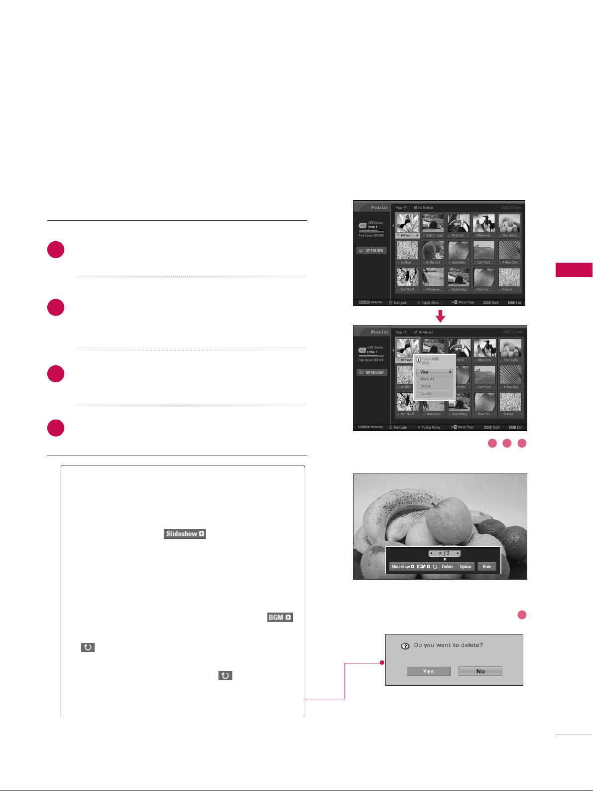
As shown, up to 15 thumbnail photos are listed per page.
Use the
CC HH
DD
or
EE
button to navigate in the thumb-
nail photo page.
Use the
MMAARRKK
button to mark or unmark a photo.
When one or more photos are marked, you can view
individual photos or a slide show of the marked photos.
If no photos are marked, you can view all photos individually or all photos in the folder in a slide show.
Use
DD EE
FF GG
button to navigate the appropriate
thumbnail photos, then press the
EENNTTEERR
button to
show the PopUp menu.
Repeatedly, press
EEXXIITT
button to return to TV viewing
or press the button to return to the Media Host
menu.
MEDIA HOST
1
2
GG
VViieeww
: Display the selected item.
GG
MMaarrkk AAllll
: Mark all photos on the screen.
GG
DDeelleettee
: Delete the selected photo item.
GG
CCaanncceell
: Close the pop-up menu.
3
4
1 2
3
Page 31
MEDIA HOST
51
Set up the menu in Full-Sized Screen
You can change the settings to display photos stored on a
USB device, on a full-sized screen.
Detailed operations are available on full-sized photo view
screen.
The aspect ratio of a photo may change the size of
the photo displayed on the screen in full size.
Use the
CC HH
DD
or
EE
button to navigate the thumbnail
photo page.
Use
DD EE
FF GG
button to navigate the appropriate
thumbnail photos, then press the
EENNTTEERR
button to
show the PopUp menu.
Use
DD
or EEbutton to Move to the
VVii eeww
menu, then
press the
EENNTTEERR
button.
The selected photo is displayed in full size.
2
1
4
3
1 2 3
4
GG
SS lliiddee SShhooww
: When no picture is selected, all photos in the current folder are displayed during slide
show. When selected, the selected photos are displayed during slide show. To start slide show, press
EENNTTEERR
button on
■ Set the time interval of the slide show in
OO ppttii oonn
.
■ A slide show continues for a maximum of 4 hours.
After 4 hours, the slide show will end and go to TV
mode or external input mode.
GG
BBGGMM
: Listen to music while viewing photos in full
size. To start BGM, press
EENNTTEERR
button on .
■ Set the BGM device and album in
OO ppttii oonn
.
GG
((RRoo ttaattee))
: Rotate photos.
■ Rotates the photo 90°, 18 0 °, 270 °, 360° clock-
wise upon
EENNTTEERR
button on
((RRoo ttaattee))
.
GG
DD eelleettee
: Delete photos. Use FFor GGbutton to
select
DD eelleettee
and press
EENNTTEERR
button.
Page 32
MEDIA HOST
52
MEDIAMEDIA
HOST HOST
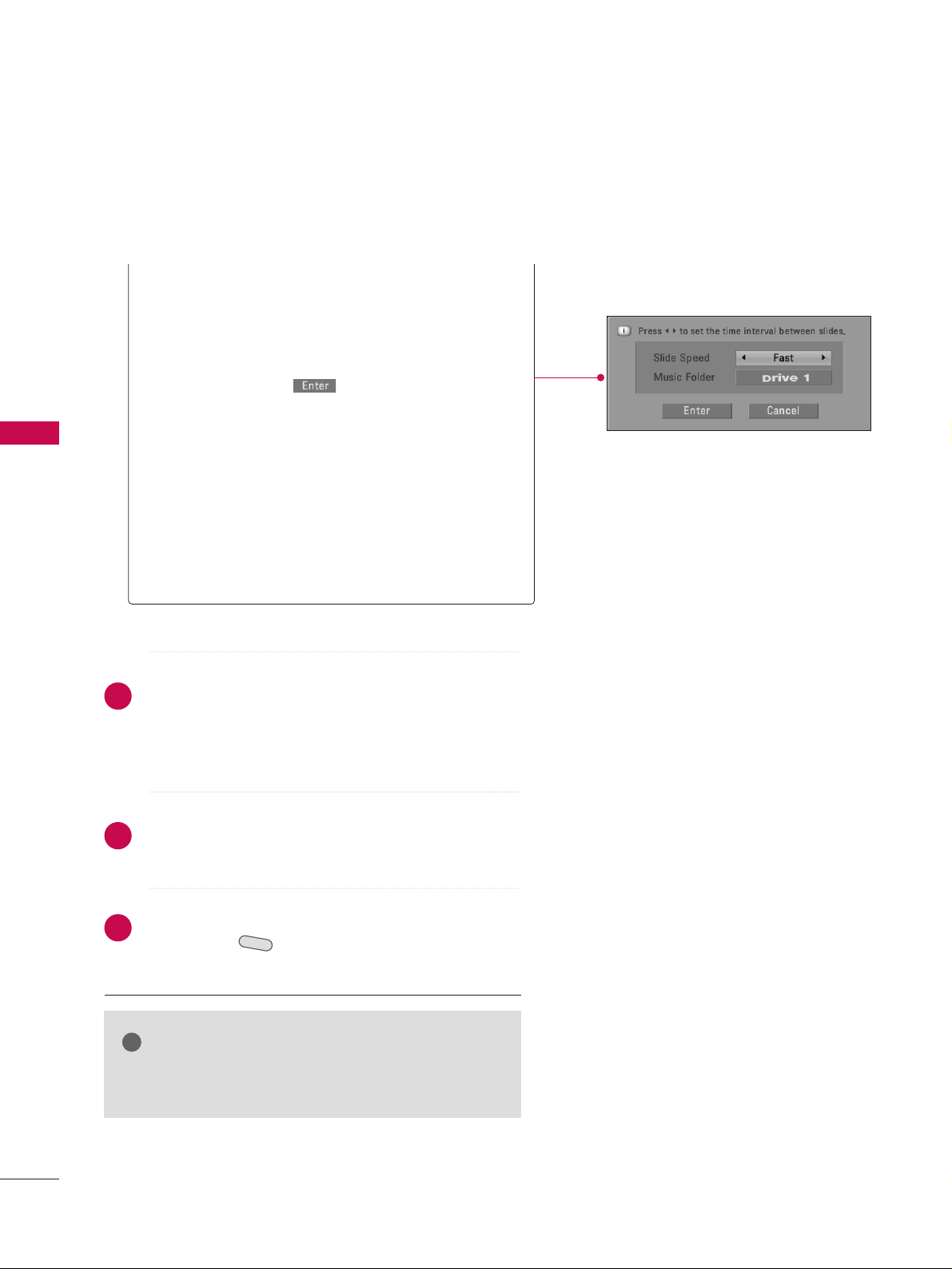
GG
OO ppttii oonn
: Set values for
SS lliiddee SS ppeeeedd
and
MMuuss iicc
ffoolldd eerr
. Use
FF
or GGbutton to select
OO ppttii oonn
and
press
EENNTTEERR
button.
■
Use
FF
or
GG
button and
EENNTTEERR
button to set val-
ues. Then go to and press
EENNTTEERR
to save
the settings.
■
You cannot change
MMuussii cc FFooll ddeerr
while BGM is
playing.
GG
HH iidd ee
: Hide the menu on the full-sized screen. Use
FF
or
GG
button to select
HH iidd ee
and press
EENNTTEERR
button.
■
To see the menu again on the full-sized screen,
press
EENNTTEERR
button to display.
Use
DD EE
FF GG
button to select the previous or next
photo.
Use
DD EE
FF GG
button to select and control the menu
on the full-sized screen.
Use
EEXXIITT
button to go back to the photo list from
the full-sized screen.
Repeatedly, press
EEXXIITT
button to return to TV viewing or press button to return to the Media Host
menu.
MEDIA HOST
NOTE
!
GG
If it is Progressive JPEG format, some photos may be
not decorded.
5
6
7
Page 33

MUSIC LIST
MEDIA HOST
53
Purchased music files(*.MP3) may contain copyright restrictions.
Playback of these files may not be supported by this model.
Music file on your USB device can be played by this unit.
The On Screen Display may be different from your set. Images
are an example to assist with the TV operation.
TV INPUTTV INPUT
STBSTB
MENU
B
R
I
G
HT
+
B
R
I
GH
T
-
TI
ME
R
RAT
I
O
S
I
M
P
L
IN
K
TV INPUT
STB
TV INPUT
STB
TV INPUT
STB
MEDIA HOSTMEDIA HOST
MEDIA HOST
MEDIA HOST
MEDIA HOST
Screen Components
Current page/Total pages
Total number of marked musics
Current playing time/Total play-
ing time
Corresponding buttons on the
remote control
Usable USB memory
1
2
3
4
5
1
2
5
3 4
Page 34
MEDIA HOST
54
MEDIAMEDIA
HOST HOST
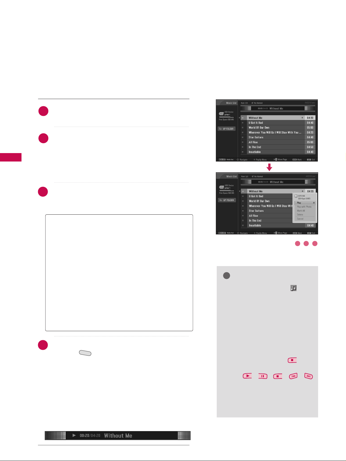
Use the
CC HH
DD
or
EE
button to navigate in the music
titles page.
Use
MMAARRKK
button to mark or unmark a music. When
one or more music files are marked, the marked musics
will be played in sequence. For example, if you want to
listen to only one music repeatedly, just mark the music
only and play it. If no music is marked, all the music in
the folder will be played in sequence.
Use
DD EE
button to navigate the appropriate musics,
then press the
EENNTTEERR
button to show up the pop-up
menu.
Repeatedly, press
EEXXIITT
button to return to TV viewing
or press button to return to the Media Host
menu.
■
If you don't press any button for a while during the
playing, the play information box (as shown in the
below) will float as a screen saver.
■
The ‘Screen Saver’?
Screen saver is to prevent screen pixel damage due to
an fixed image remaining on the screen for a extended period of time.
MEDIA HOST
Music Selection and PopUp Menu
As shown , up to 8 music titles are listed per page.
NOTE
!
GG
When music is playing, is displayed in front of the music title.
GG
A damaged or corrupted music
does not play but displays 00:00 in
playtime.
GG
A music downloaded from a paid
service with copyright protection
does not start but displays inappropriate information in playtime.
GG
If you press
EENNTTEERR
,
,
EEXXIITT
buttons, screen saver is stopped.
GG
The
,,,,
buttons on the remote control are
also available in this mode.
GG
It’s not avaiable to playe MP3 file
under 16Kbyt.
GG
PP llaayy
(During stop): Play the selected musics.
Once a music finishes playing, the next selected one
will be played. When there are no selected musics to
play, the next one in the current folder will be
played. If you go to a different folder and press the
EENNTTEERR
button, the current music in playback will
stop.
GG
SS ttoopp PPll aayy
(During playback): Stop the playing
musics.
GG
PP llaayy WWiitthh PP hhoott oo
: Start playing the selected musics
and then move to the Photo List.
GG
MMaarr kk AAllll
: Mark all musics in the folder.
GG
DD eelleettee
: Delete the selected musics.
GG
CCaanncceell
: Close the pop-up menu.
1
2
3
4
1 2 3
Page 35

PICTURE CONTROL
55
PICTURE SIZE (ASPECT RATIO) CONTROL
PICTURE CONTROL
TV INPUTTV INPUT
STBSTB
M
E
N
U
BRIGHT +
BR
I
G
H
T
-
T
I
M
E
R
S
I
MP
L
IN
K
TV INPUT
STB
RAT
I
ORATIO
MEDIA HOSTMEDIA HOST
MEDIA HOST
This feature lets you choose the way an analog picture with a 4:3 aspect ratio is
displayed on your TV. When you receive an analog picture with a 4:3 aspect ratio
on your 16:9 TV, you need to specify how the picture is to be displayed.
■
RGB-PC input source use 4:3 or 16:9 aspect ratio.
■
DTV, CADTV, HDMI, or DVI input source use
JJ uuss tt SSccaann
.
NOTE
!
GG
If a fixed image is displayed on the screen for a long time, the image may
become imprinted on the screen and remain visible.
This phenomenon is common to all manufactures and in consequence the
manufactures warranty does not cover the product bearing this phenomenon.
Press the
RRAATTIIOO
button repeatedly to select the desired picture format.
■
You can also adjust
AAssppeecctt RRaattiioo
in the
PPIICCTTUURREE
menu.
1
Set by program
Selects the proper picture proportion to match
the source’s image.
4:3
Choose 4:3 when you want to view a picture
with an original 4:3 aspect ratio.
16:9
Adjust the picture horizontally, in a linear proportion to fill the entire screen.
Zoom 1
Choose Zoom 1 when you want to view the picture without any alteration. However, the top and
bottom portions of the picture will be cropped.
Zoom 2
Choose Zoom 2 when you want the picture to be
altered, both vertically extended and cropped.
The picture taking a halfway trade off between
alteration and screen coverage.
Just Scan
Following selection will lead to you view the picture of best quality without loss of original picture in high resolution image.
Set By Program
4:3
16 : 9
Just Scan
Zoom 1
Zoom 2
Set By Program
(4:3 4:3)
(16:9 16:9)
Page 36

PICTURE CONTROL
56
PRESET PICTURE SETTINGS
PICTURE CONTROL
TV INPUT
STB
BACKBACK
SOUNDSOUND
SAPSAP
CCCC
MARKMARK
USB EJECTUSB EJECT
TV INPUT
STB
BACK
PICTURE
SOUND
SAP
CC
MARK
USB EJECT
TV INPUT
STB
BACK
PICTURE
SOUND
SAP
CC
MARK
USB EJECT
TV INPUT
STB
BACK
PICTURE
SOUND
SAP
CC
MARK
USB EJECT
TV INPUT
STB
BACK
PICTURE
SOUND
SAP
CC
MARK
USB EJECT
PICTURE
MEDIA HOST
MEDIA HOST
MEDIA HO
ST
MEDIA HOST
MEDIA HOST
Picture Mode - Preset
Press the
PP II CCTT UURR EE
button repeatedly to select the picture
appearance setup option as below :
II nntteelllliiggeenntt EEyyee
(LCD TV only),
DD yynnaammiicc, SS ttaannddaarrdd
,
MMii lldd, UU sseerr11
, and
UU sseerr22
(your own settings).
Press the
EEXXIITT
button to save and return to TV viewing.
Picture Mode adjusts the TV for the best picture appearance.
Select the preset value in the Picture Mode menu based on the
program category.
II nntteell ll iigg eenntt EEyyee, DD yynnaammiicc, SStt aannddaarr dd, MM ii lldd
Settings are preset for the optimum picture quality at the factory and are not
adjustable.
In the
UU ss eerr 11
and
UU ss eerr 22
modes only, user can directly adjust
the contrast, brightness, color, sharpness, tint.
■
You can also use the
PPIICCTTUURREE
menu to adjust
PP iiccttuurree MMooddee
.
2
1
Picture Mode
G
Color Temperature
XD
Advanced
Aspect Ratio
Picture Reset
Screen
Intelligent Eye
Dynamic
Standard
Mild
User 1
User 2
Picture Mode : User1
Color Temperature : Cool
XD
Advanced
Aspect Ratio : 16:9
Picture Reset
Screen
Page 37

PICTURE CONTROL
57
TV INPUTTV INPUT
STBSTB
BRIGHT +
BRI
G
H
T
-
T
I
M
E
R
R
A
T
I
O
S
I
M
P
LINK
M
E
N
U
TV INPUT
STB
TV INPUT
STB
TV INPUT
STB
TV INPUT
STB
MEDIA HOSTMEDIA HOST
MEDIA HOST
MEDIA HOST
MEDIA HOST
MEDIA HOST
Color Tone - Preset
Choose one of three automatic color adjustments. Set to
warm to enhance hotter colors such as red, or set to cool
to see less intense colors with more blue.
When selecting Picture Mode options (Dynamic, Standard
and Mild),
CCoolloorr TTeemmppeerraattuurree
is automatically change.
When selecting Picture Mode options (User 1 and User 2),
you can choose the
CCoolloorr TTeemmppeerraattuurree
.
Press the
MMEENNUU
button and then use
DD
or EEbutton
to select the
PP II CCTT UURR EE
menu.
Press the GGbutton and then useDDor EEbutton to
select
CCooll oorr TTeemmppeerraatt uurr ee
.
Press the
GG
button and then useDDor EEbutton to
select either
CCoo ooll,MMeeddii uu mm, WWaarrmm
or
UU ss eerr
.
Press
EEXXIITT
button to return to TV viewing or press
MMEENNUU
button to return to the previous menu.
2
3
4
1
1
2 3
Picture Mode
Color Temperature
G
XD
Advanced
Aspect Ratio
Picture Reset
Screen
Cool
Medium
Warm
User
Picture Mode : User1
Color Temperature : Cool
XD
Advanced
Aspect Ratio : 16:9
Picture Reset
Screen
Page 38
PICTURE CONTROL
58
MANUAL PICTURE ADJUSTMENT
PICTURE CONTROL
TV INPUTTV INPUT
STBSTB
BRIG
HT +
BRI
G
H
T
-
T
I
M
E
R
R
A
T
I
O
S
I
M
P
LINK
M
E
N
U
TV INPUT
STB
TV INPUT
STB
TV INPUT
STB
TV INPUT
STB
MEDIA HOSTMEDIA HOST
MEDIA HOST
MEDIA HOST
MEDIA HOST
MEDIA HOST
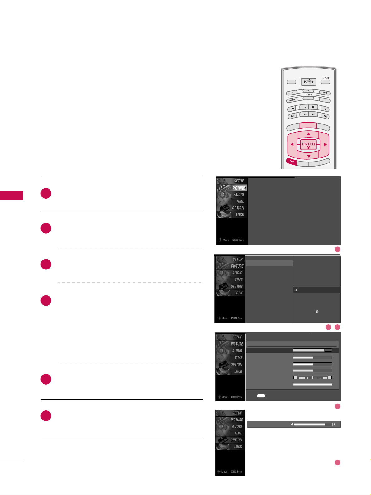
Picture Mode - User Mode
Adjust the picture appearance to suit your preference and
viewing situations.
Press the
MMEENNUU
button and then use
DD
or EEbutton
to select the
PP II CCTT UURR EE
menu.
Press the GGbutton and then useDDor EEbutton to
select
PP iiccttuurree MMooddee
.
Press the
GG
button and then useDDor EEbutton to
select
UU sseerr 11
or
UU sseerr22
.
Press the
GG
button and then useDDor EEbutton to
select the desired picture option
((
CCoonnttrr aa sstt
,
BBrriigghhttnneessss,CCoolloorr,SShhaarrppnneessss
,
TTiinntt
, or
BBaacckk LLiigghhtt
))
.
■
BBaacckk LL iigghhtt
To control the brightness of the screen, adjust the
brightness of LCD panel.
Press the
GG
button and then useFFor GGbutton to
make appropriate adjustments.
Press
EEXXIITT
button to return to TV viewing or press
MMEENNUU
button to return to the previous menu.
2
3
4
5
6
1
Contrast 85
EE
Picture Mode : User1
Color Temperature : Cool
XD
Advanced
Aspect Ratio : 16:9
Picture Reset
Screen
EE
User1
Contrast 85
G
Brightness 50
Color 50
Sharpness 50
Tint 0
Back Light 100
R G
Press to confirm.
MENU
Picture Mode
Color Temperature
XD
Advanced
Aspect Ratio
Picture Reset
Screen
Intelligent Eye
Dynamic
Standard
Mild
User 1
G
User 2
Selection ( Gor ) leads you to
the detailed setting screen.
1
2 3
4
5
Page 39

PICTURE CONTROL
59
TV INPUTTV INPUT
STBSTB
BRIGH
T +
BRI
G
HT
-
T
I
M
E
R
R
A
TIO
S
IMP
LINK
M
E
N
U
TV INPUT
STB
TV INPUT
STB
TV INPUT
STB
TV INPUT
STB
MEDIA HOSTMEDIA HOST
MEDIA HOST
MEDIA HOST
MEDIA HOST
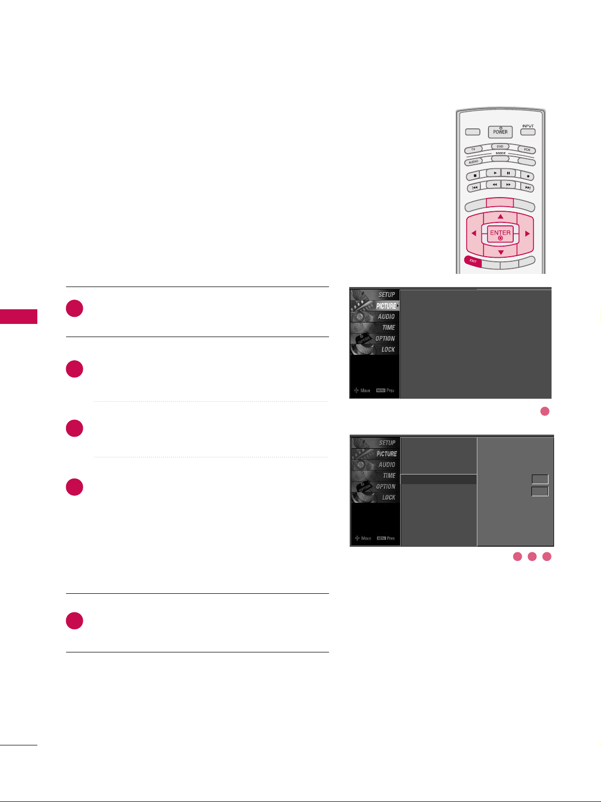
You can also adjust the detailed settings (Red, Green, Blue)
by selecting the
CCoolloorr TTeemmppeerraattuu rr ee --UU sseerr
menu.
This feature operate only if the picture mode set
UU sseerr 11
or
UU sseerr 22
.
Color Tone - User Mode
Press the
MMEENNUU
button and then useDDor EEbutton
to select the
PP II CCTT UURR EE
menu.
Press the GGbutton and then useDDor EEbutton to
select
CCooll oorr TTeemmppeerraatt uurr ee
.
Press the
GG
button and then useDDor EEbutton to
select
UU ss eerr
.
Press the
GG
button and then useDDor EEbutton to
select
RReedd, GG rreeeenn
, or
BBll uuee
.
Press the
GG
button and then useFFor GGbutton to
make appropriate adjustments.
■
The adjustment range of
RRee dd, GG rr ee eenn
, or
BBll uuee
is
-20~ +20.
Press
EEXXIITT
button to return to TV viewing or press
MMEENNUU
button to return to the previous menu.
2
3
4
5
6
1
Red 0
EE
Picture Mode
Color Temperature
XD
Advanced
Aspect Ratio
Picture Reset
Screen
Press to confirm.
MENU
Selection ( Gor ) leads you to
the detailed setting screen.
Cool
Medium
Warm
User
G
User
Red 0
G
Green 0
Blue 0
Picture Mode : User1
Color Temperature : Cool
XD
Advanced
Aspect Ratio : 16:9
Picture Reset
Screen
EE
1
2 3
4
5
Page 40

PICTURE CONTROL
60
XD - PICTURE IMPROVEMENT TECHNOLOGY
PICTURE CONTROL
TV INPUTTV INPUT
STBSTB
BRIG
HT +
BRI
G
H
T
-
T
I
M
E
R
R
A
T
I
O
S
I
M
P
LINK
M
E
N
U
TV INPUT
STB
TV INPUT
STB
TV INPUT
STB
TV INPUT
STB
MEDIA HOSTMEDIA HOST
MEDIA HOST
MEDIA HOST
MEDIA HOST
MEDIA HOST
Press the
MMEENNUU
button and then useDDor EEbutton
to select the
PP II CCTT UURR EE
menu.
Press the
GG
button and then useDDor EEbutton to
select
XX DD
.
Press the
GG
button and then useFFor GGbutton to
select
AAuu ttoo orMMaannuuaall
.
Press
EEXXIITT
button to return to TV viewing or press
MMEENNUU
button to return to the previous menu.
XD is LG Electronic’s unique picture improving technology
to display a real HD source through an advanced digital signal processing algorithm.
When selecting Picture Mode options (Dynamic, Standard,
and Mild), XD is automatically changed to Auto.
When selecting Picture Mode options (User 1 and User 2),
you can choose the Auto / Manual.
When selecting the Manual, you can adjust the XD
Contrast, XD color and XD Noise.
Picture Mode
Color Temperature
XD
G
Advanced
Aspect Ratio
Picture Reset
Screen
Manual
XD Contrast On
XD Color On
XD Noise On
2
3
4
1
SSeell eeccttiinngg tthh ee MMaa nnuuaall
1. Press the
EE
button and then use DDor EEbut-
ton to select
XXDD CC oonnttrr aasstt, XXDD CC oolloorr
or
XXDD NN ooiissee
.
■
XXDD CCoonnttrr aa sstt ::
Optimizing the contrast
automatically according to the brightness of
the reflection.
■
XXDD CC oolloorr::
Adjusting the colors of the
reflection automatically to reproduce as
closely as possible to the natural colors.
■
XXDD NN ooiiss ee ::
Removing the noise up to the
point where it does not damage the original
picture.
2. Use the
FF
or GGbutton to select
OO nn
or
OO ffff
.
Picture Mode : User1
Color Temperature : Cool
XD
Advanced
Aspect Ratio : 16:9
Picture Reset
Screen
1
2 3
Page 41

PICTURE CONTROL
61
ADVANCED - CINEMA 3:2 PULL DOWN MODE
TV INPUTTV INPUT
STBSTB
BRIGHT +
BRI
G
H
T
-
T
I
M
E
R
R
A
T
I
O
S
I
M
P
LINK
M
E
N
U
TV INPUT
STB
TV INPUT
STB
TV INPUT
STB
TV INPUT
STB
MEDIA HOSTMEDIA HOST
MEDIA HOST
MEDIA HOST
MEDIA HOST
MEDIA HOST
Press the
MMEENNUU
button and then useDDor EEbutton
to select the
PP II CCTT UURR EE
menu.
Press the GGbutton and then useDDor EEbutton to
select
AAddvv aa nncceedd
.
Press the
GG
button and then useDDor EEbutton to
select
CCiinneemm aa 33 ::22 MMoodd ee
.
Use
FF
or GGbutton to select
OO nn
or
OO ffff
.
Press
EEXXIITT
button to return to TV viewing or press
MMEENNUU
button to return to the previous menu.
Set up the TV for the best picture appearance for viewing
movies.
When you operate Cinema 3:2 Mode (3:2 Pull-Down Mode
or Cinema Correction Mode), the TV will adjust 24 fps
video from movies to 30 fps video for display.
This feature operates only in TV (Analog, DTV), AV1, AV2,
and Component 480i mode.
2
3
4
5
1
Picture Mode
Color Temperature
XD
Advanced
G
Aspect Ratio
Picture Reset
Screen
Cinema 3:2 Mode Off
Black Level Low
Picture Mode : User1
Color Temperature : Cool
XD
Advanced
Aspect Ratio : 16:9
Picture Reset
Screen
2 3 4
1
Page 42
PICTURE CONTROL
62
ADVANCED - BLACK (DARKNESS) LEVEL
PICTURE CONTROL
TV INPUTTV INPUT
STBSTB
BRIGHT +
BRI
G
H
T
-
T
I
M
E
R
R
A
T
I
O
S
I
M
P
LINK
M
E
N
U
TV INPUT
STB
TV INPUT
STB
TV INPUT
STB
TV INPUT
STB
MEDIA HOSTMEDIA HOST
MEDIA HOST
MEDIA HOST
MEDIA HOST
MEDIA HOST
Press the
MMEENNUU
button and then useDDor EEbutton
to select the
PP II CCTT UURR EE
menu.
Press the GGbutton and then useDDor EEbutton to
select
AAddvv aa nncceedd
.
Press the
GG
button and then useDDor EEbutton to
select
BBllaacckk lleevveell
.
Press the
GG
button and then useFFor GGbutton to
select
LLooww
or
HH iigghh
.
■
LLooww
The screen gets darker.
■
HH iigghh
The screen gets brighter.
Press
EEXXIITT
button to return to TV viewing or press
MMEENNUU
button to return to the previous menu.
Adjusting the contrast and the brightness of the screen
using the black level of the screen.
This feature operates only in AV1, AV2, HDMI1, HDMI2, or
HDMI3 mode.
2
3
4
5
1
Picture Mode
Color Temperature
XD
Advanced
G
Aspect Ratio
Picture Reset
Screen
Cinema 3:2 Mode Off
Black Level Low
Picture Mode : User1
Color Temperature : Cool
XD
Advanced
Aspect Ratio : 16:9
Picture Reset
Screen
2 3 4
1
Page 43
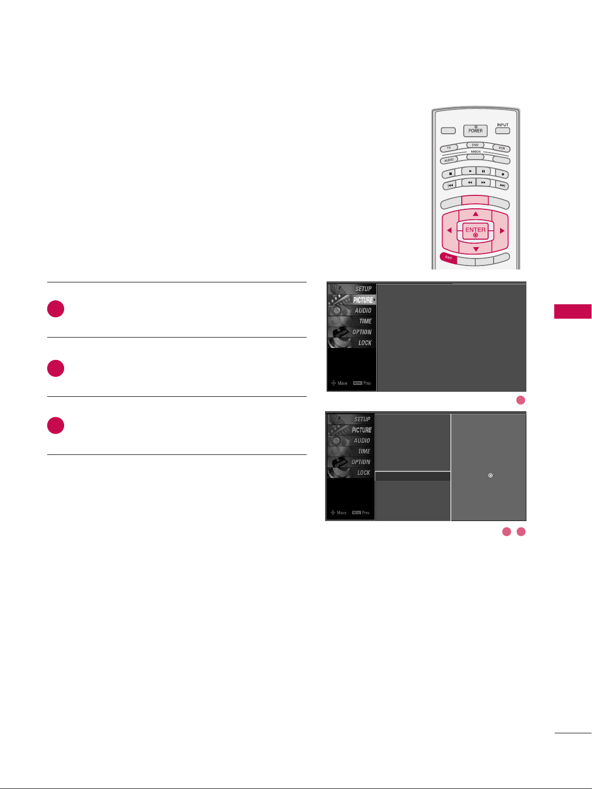
PICTURE CONTROL
63
PICTURE RESET
TV INPUTTV INPUT
STBSTB
BRIGHT +
BRI
G
H
T
-
T
I
M
E
R
R
A
T
I
O
S
I
M
P
LINK
M
E
N
U
TV INPUT
STB
TV INPUT
STB
TV INPUT
STB
TV INPUT
STB
MEDIA HOSTMEDIA HOST
MEDIA HOST
MEDIA HOST
MEDIA HOST
MEDIA HOST
Press the
MMEENNUU
button and then useDDor EEbutton
to select the
PP II CCTT UURR EE
menu.
Press the GGbutton and then useDDor EEbutton to
select
PPiiccttuurree RReesseett
.
Press the
GG
button to reset the Picture menu options
to original values.
Use to quickly reset all the Picture menu options to their
original factory preset values.
2
3
1
Picture Mode
Color Temperature
XD
Advanced
Aspect Ratio
Picture Reset
G
Screen
Selection ( Gor ) resets to the
factory settings(defaults).
Picture Mode : User1
Color Temperature : Cool
XD
Advanced
Aspect Ratio : 16:9
Picture Reset
Screen
2 3
1
Page 44
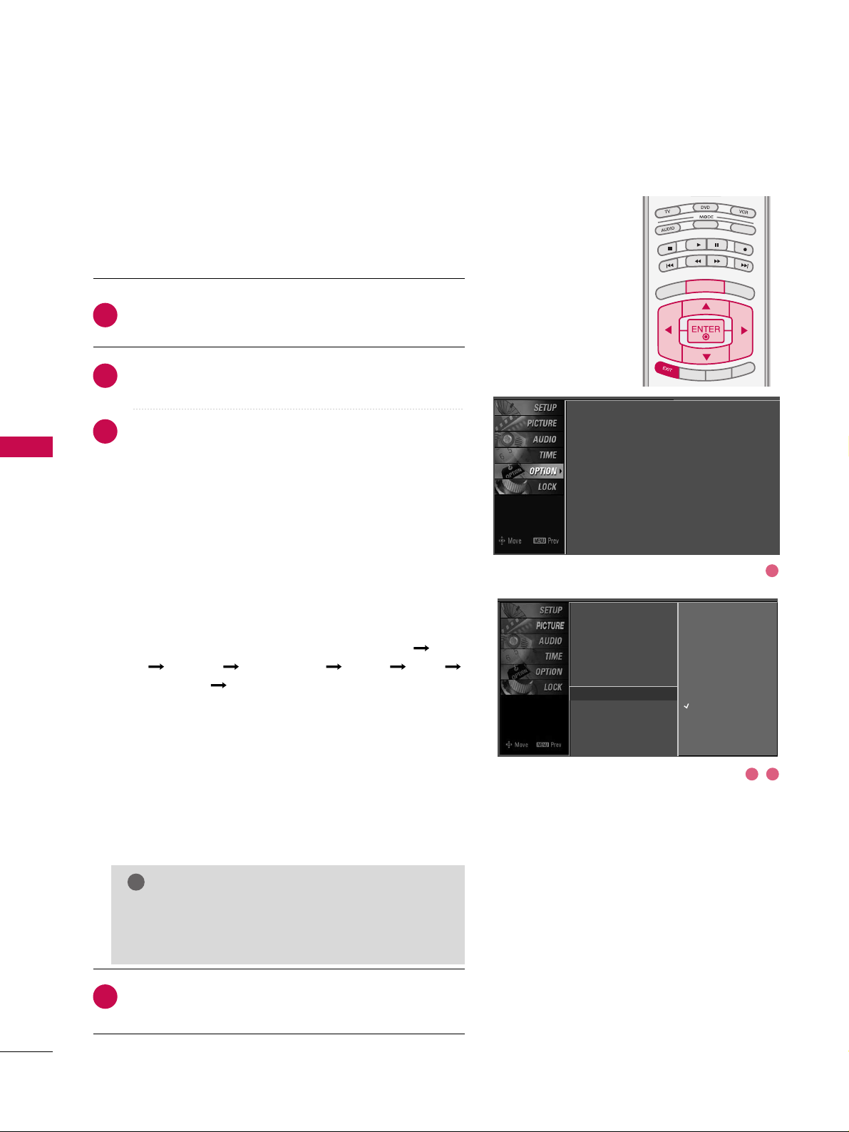
PICTURE CONTROL
64
IMAGE STICKING MINIMIZATION (ISM) METHOD
-
Plasma TV only
PICTURE CONTROL
TV INPUT
STBSTB
BRIGHT +
BRI
G
H
T
-
T
I
M
E
R
R
A
T
I
O
S
I
M
P
LINK
M
E
N
U
TV INPUT
STB
TV INPUT
STB
TV INPUT
STB
TV INPUT
STB
MEDIA HOSTMEDIA HOST
MEDIA HOST
MEDIA HOST
MEDIA HOST
MEDIA HOST
Press the
MMEENNUU
button and then useDDor EEbutton
to select the
OO PPTTII OONN
menu.
Press the
GG
button and then useDDor EEbutton to
select
II SSMM MM eett hhoodd
.
Press the
GG
button and then useDDor EEbutton to
select either
NNoorrmm aa ll, OO rrbb iitteerr, II nnvveerrss iioonn
, or
WWhhiitt ee
WWaasshh
.
■
NNoorrmm aa ll
If image sticking is never a problem, ISM is not neces-
sary - set to Normal.
■
OO rrbb iitteerr
Orbiter may help prevent ghost images. However, it is
best not to allow any fixed image to remain on the
screen. To avoid a ghost image on the screen, the
image will move once per 2 minutes : Left Right
Upside Downside Right Left
Downside Upside.
■
II nnvveerrss iioonn
Inversion will automatically invert the plasma display
panel color every 30 minutes.
■
WWhhiittee WWaass hh
White Wash removes ghost images from the screen.
Use sparingly. Watch the TV normally for a while before
using this feature to see if the ghost image disappears on
its own.
Press
EEXXIITT
button to return to TV viewing or press
MMEENNUU
button to return to the previous menu.
2
3
4
1
A frozen still picture from a PC/video game displayed on the
screen for prolonged periods will result in a ghost image.
Use our unique method to minimize any fixed image on the
screen.
GG
An excessive ghosted image may be impossible to
clear entirely with White Wash. To return to normal viewing, press the any button.
NOTE
!
Language : English
Input Label
SimpLink : Off
Key Lock : Off
Caption : Off
ISM Method : Orbiter
Low Power : Off
Front Display : Bright
Set ID : 1
Language
Input Label
SimpLink
Key Lock
Caption
ISM Method
G
Low Power
Front Display
Set ID
Normal
Orbiter
Inversion
White Wash
2 3
1
Page 45

PICTURE CONTROL
65
LOW - POWER PICTURE MODE
-
Plasma TV only
TV INPUTTV INPUT
STBSTB
BRIGH
T +
BRI
G
HT
-
T
I
M
E
R
R
A
TIO
S
IMP
LINK
M
E
N
U
TV INPUT
STB
TV INPUT
STB
TV INPUT
STB
TV INPUT
STB
MEDIA HOSTMEDIA HOST
MEDIA HOST
MEDIA HOST
MEDIA HOST
Low power reduces the plasma display power consumption.
Press the
MMEENNUU
button and then use
DD
or EEbutton
to select the
OO PPTTII OONN
menu.
Press the
GG
button and then useDDor EEbutton to
select
LLoo ww PPoo wweerr
.
Press the GGbutton and then useDDor EEbutton to
select
OO nn
or
OO ffff
.
■
When you select
OO nn
, the screen darkens.
Press
EEXXIITT
button to return to TV viewing or press
MMEENNUU
button to return to the previous menu.
2
3
4
1
Language :
English
Input Label
SimpLink : Off
Key Lock : Off
Caption : Off
ISM Method : Orbiter
Low Power : Off
Front Display : Bright
Set ID : 1
Language
Input Label
SimpLink
Key Lock
Caption
ISM Method
Low Power
G
Front Display
Set ID
Off
On
2 3
1
Page 46

PICTURE CONTROL
66
FRONT DISPLAY
-
Plasma TV only
PICTURE CONTROL
Press the
MMEENNUU
button and then useDDor EEbutton
to select the
OO PPTTII OONN
menu.
Press the
GG
button and then useDDor EEbutton to
select
FFrroonntt DDii sspp llaayy
.
Press the GGbutton and then useDDor EEbutton to
select
OO ffff, DD aarrkk
or
HH BB rrii gghhtt
.
Press
EEXXIITT
button to return to TV viewing or press
MMEENNUU
button to return to the previous menu.
Illuminates brightly when the set is turned on. The LED displays current TV status.
2
3
4
1
TV INPUTTV INPUT
STBSTB
BRIGHT +
BRI
G
H
T
-
T
I
M
E
R
R
A
T
I
O
S
I
M
P
LINK
M
E
N
U
TV INPUT
STB
TV INPUT
STB
TV INPUT
STB
TV INPUT
STB
MEDIA HOSTMEDIA HOST
MEDIA HOST
MEDIA HOST
MEDIA HOST
MEDIA HOST
Language : English
Input Label
SimpLink : Off
Key Lock : Off
Caption : Off
ISM Method : Orbiter
Low Power : Off
Front Display : Bright
Set ID : 1
Language
Input Label
SimpLink
Key Lock
Caption
ISM Method
Low Power
Front Display
G
Set ID
Off
Dark
Bright
3 42
1
Page 47
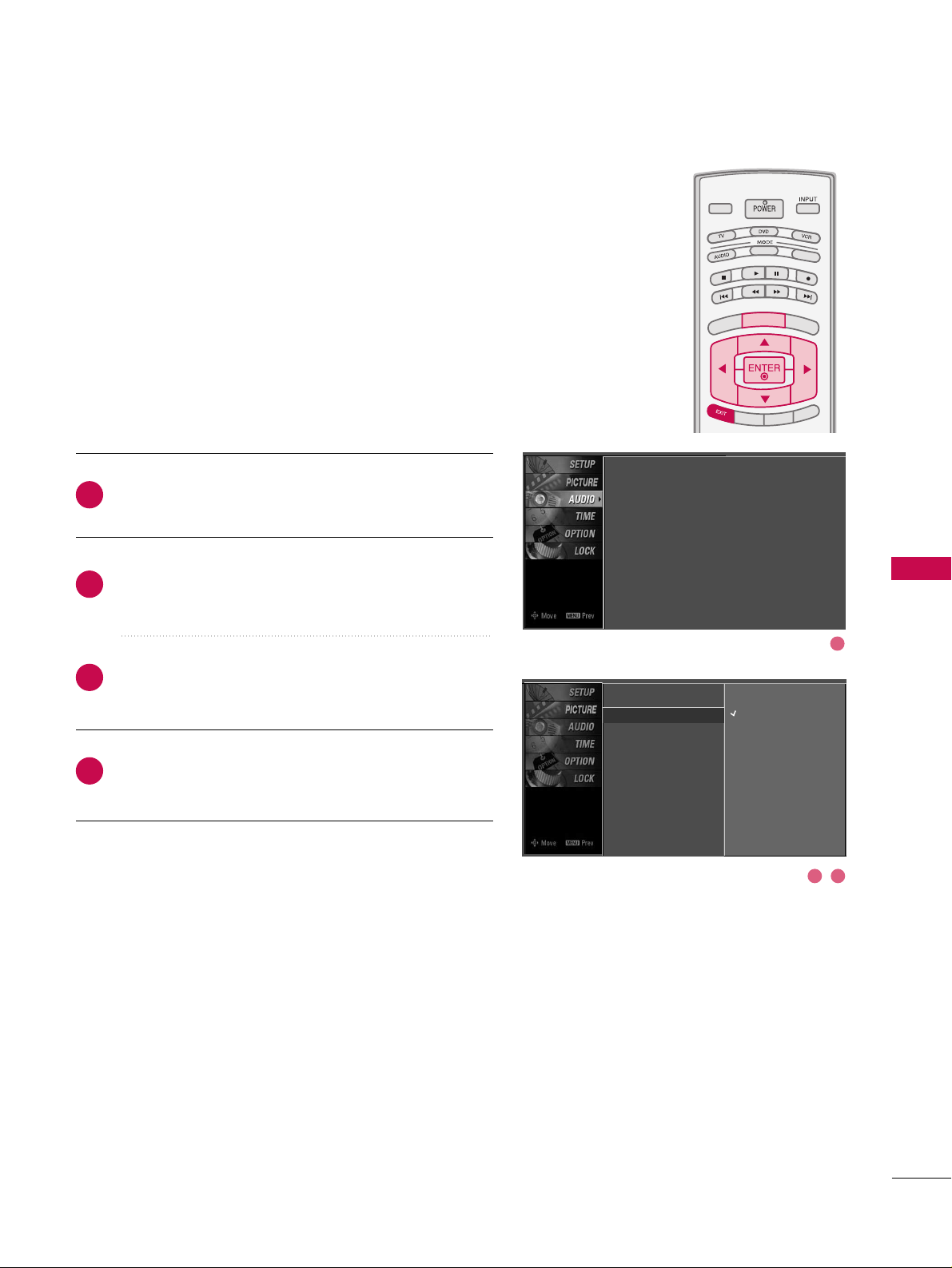
SOUND & LANGUAGE CONTROL
67
TV INPUTTV INPUT
STBSTB
BRIGHT +
BRI
G
H
T
-
T
I
M
E
R
R
A
T
I
O
S
I
M
P
LINK
M
E
N
U
TV INPUT
STB
TV INPUT
STB
TV INPUT
STB
TV INPUT
STB
MEDIA HOSTMEDIA HOST
MEDIA HOST
MEDIA HOST
MEDIA HOST
MEDIA HOST
AUTO VOLUME LEVELLER (AUTO VOLUME)
SOUND & LANGUAGE CONTROL
Press the
MMEENNUU
button and then useDDor EEbutton
to select the
AAUU DDIIOO
menu.
Press the GGbutton and then useDDor EEbutton to
select
AAuu ttoo VVooll uummee
.
Press the
GG
button and then useDDor EEbutton to
select
OO nn
or
OO ffff
.
Press
EEXXIITT
button to return to TV viewing or press
MMEENNUU
button to return to the previous menu.
Scans for changes in sound levels during commercials, then
adjusts the sound to match the specified audio level. Auto
Volume makes sure that the volume level remains consistent
whether you are watching a commercial or a regular TV program.
2
3
4
1
Sound Mode
Auto Volume
G
Balance
TV Speaker
Off
On
Sound Mode : Standard
Auto Volume : On
Balance : 0
TV Speaker : On
2 3
1
Page 48

TV INPUT
STB
BACKBACK
PICTUREPICTURE
SOUND
SAPSAP
CCCC
MARKMARK
USB EJECTUSB EJECT
TV INPUT
STB
BACK
PICTURE
SOUND
CC
MARK
USB EJECT
TV INPUT
STB
BACK
PICTURE
SOUND
SAP
MARK
USB EJECT
TV INPUT
STB
BACK
SOUND
SAP
CC
MARK
USB EJECT
TV INPUT
PICTURE
MARK
MEDIA HOST
MEDIA HOST
MEDIA HOST
MEDIA HOST
SOUND & LANGUAGE CONTROL
68
PRESET SOUND SETTINGS (SOUND MODE)
Sound Mode lets you enjoy the best sound without any special
adjustment because the TV sets the appropriate sound options
based on the program content.
SStt aannddaarr dd, MM uu ssii cc, MM oovvii ee
, and
SSpp oorrttss
are preset for good
sound quality at the factory and are not adjustable.
Press the
SSOOUUNNDD
button repeatedly to select the appropriate
sound setup as below :
SS ttaannddaarrdd, MMuussiicc, MMoovviiee, SS ppoorrtt ss
, and
UU sseerr
(
your own
settings
).
Press
EEXXIITT
button to return to TV viewing.
■
You can also adjust
SS oouunn dd MM ooddee
in the
AAUUDDIIOO
menu.
2
1
Sound Mode
G
Auto Volume
Balance
TV Speaker
Standard
Music
Movie
Sports
User
Sound Mode : Standard
Auto Volume : On
Balance : 0
TV Speaker : On
Page 49

SOUND & LANGUAGE CONTROL
69
SOUND SETTING ADJUSTMENT - USER MODE
Front Surround 3D EchoSound System
SSRR SS TTrruuSSuurr rroo uunndd XXTT
Takes advantage of any multi-channel format without
needing to add extra speakers or equipment. Dialog clarity,
bass enrichment, and the addition of stereo audio
enhancement produces an immersive sound experience
from standard stereo material.
33DD EE cchh ooSSoouunndd SS yysstteemm
Creates a stunning simulated stereo effect from any mono
sound and a realistic three-dimensional sound with a very
wide and deep sound stage.
Press the
MMEENNUU
button and then use
DD
or EEbutton
to select the
AAUU DDIIOO
menu.
Press the
GG
button and then useDDor EEbutton to
select
SS oouunn dd MM ooddee
.
Press the
GG
button and then useDDor EEbutton to
select
UU ss eerr
.
Press the GGbutton and then useDDor EEbutton to
select the desired sound option (
TTrreebb llee,BBaassss
,or
FFrroonntt SSuurrrroouunndd
).
Press the
GG
button and then useFFor GGbutton to
make appropriate adjustments.
SS eell eecc ttiinngg tthhee FFrroonntt ss uurr rroo uunndd
Press the
GG
button and then use FFor GGbutton to
select
OO ffff, 33DD EEcchhooSSoouunn dd SS yysstteemm
or
SS RRSS
(
Sound
Retrieval System)
TTrruuSS uurr rroouunn dd XXTT
.
Press
EEXXIITT
button to return to TV viewing or press
MMEENN UU
button to return to the previous menu.
Adjust the sound to suit your taste and room situations.
Sound Mode
Auto Volume
Balance
TV Speaker
Selection ( Gor ) leads you to
the detailed setting screen.
Standard
Music
Movie
Sports
User
G
2
3
4
5
6
1
Sound Mode : Standard
Auto Volume : On
Balance : 0
TV Speaker : On
User
Treble 50
G
Bass 50
Front Surround Off
Press to confirm.
MENU
1
2 3
4
5
Page 50

SOUND & LANGUAGE CONTROL
70
BALANCE
SOUND &LANGUAGE CONTROL
TV INPUTTV INPUT
STBSTB
BRIGHT +
BRI
G
H
T
-
T
I
M
E
R
R
A
T
I
O
S
I
M
P
LINK
M
E
N
U
TV INPUT
STB
TV INPUT
STB
TV INPUT
STB
TV INPUT
STB
MEDIA HOSTMEDIA HOST
MEDIA HOST
MEDIA HOST
MEDIA HOST
MEDIA HOST
Press the
MMEENNUU
button and then useDDor EEbutton
to select the
AAUU DDIIOO
menu.
Press the GGbutton and then useDDor EEbutton to
select
BBaallaannccee
.
Press the
GG
button and then useFFor GGbutton to
make appropriate adjustments.
Press
EEXXIITT
button to return to TV viewing or press
MMEENN UU
button to return to the previous menu.
Adjust the left/right sound of speaker to suit your taste and
room situations.
L R
Balance 0
2
3
4
1
Sound Mode
Auto Volume
Balance 0
TV Speaker
L R
Sound Mode : Standard
Auto Volume : On
Balance : 0
TV Speaker : On
1
2
3
Page 51

SOUND & LANGUAGE CONTROL
71
TV SPEAKERS ON/OFF SETUP
TV INPUTTV INPUT
STBSTB
BRIGHT +
BRI
G
H
T
-
T
I
M
E
R
R
A
T
I
O
S
I
M
P
LINK
M
E
N
U
TV INPUT
STB
TV INPUT
STB
TV INPUT
STB
TV INPUT
STB
MEDIA HOSTMEDIA HOST
MEDIA HOST
MEDIA HOST
MEDIA HOST
MEDIA HOST
Press the
MMEENNUU
button and then useDDor EEbutton
to select the
AAUU DDIIOO
menu.
Press the
GG
button and then useDDor EEbutton to
select
TTVV SSppeeaakkeerr
.
Press the
GG
button and then useDDor EEbutton to
select
OO nn
or
OO ffff
.
Press
EEXXIITT
button to return to TV viewing or press
MMEENN UU
button to return to the previous menu.
Turn the TV speakers off if using external audio equipment.
Feature turns the TV Speakers option On or Off.
Sound Mode
Auto Volume
Balance
TV Speaker
G
Off
On
2
3
4
1
Sound Mode : Standard
Auto Volume : On
Balance : 0
TV Speaker : On
1
32
Page 52

SOUND & LANGUAGE CONTROL
72
STEREO/SAP BROADCAST SETUP
SOUND &LANGUAGE CONTROL
TV INPUT
STB
BACKBACK
PICTUREPICTURE
SOUNDSOUND
SAP
CC
CC
MARKMARK
USB EJECTUSB EJECT
TV INPUT
STB
BACK
PICTURE
SOUND
SAP
MARK
USB EJECT
TV INPUT
STB
BACK
SOUND
SAP
CC
MARK
USB EJECT
TV INPUT
STB
BACK
PICTURE
SOUND
SAP
CC
MARK
USB EJECT
TV INPUT
STB
BACK
PICTURE
SOUND
SAP
CC
MARK
USB EJECT
MEDIA HOST
MEDIA HOST
MEDIA HOST
MEDIA HOST
MEDIA HO
ST
This TV can receive MTS stereo programs and any SAP (Secondary
Audio Program)that accompanies the stereo program if the station transmits an additional sound signal as well as the original
one and when you select Stereo or SAP on the remote control.
Mono sound is automatically received if the broadcast is only in
Mono; even though Stereo or SAP has been selected.
Select Mono if you want to listen to the mono sound in remote
areas during stereo/SAP broadcasting.
Stereo or SAP can be received in Analog channel.
Use the
SS AA PP
button to select your desired MTS mode in
analog signal. Each time you press the
SS AA PP
button,
MMoo nnoo
,
SS tteerr eeoo
, or
SS AA PP
appear in turn.
■
If other languages available on the digital signal, select
them with the
SS AA PP
button.
Press
EEXXIITT
button to save and return to TV viewing.
2
1
Page 53

SOUND & LANGUAGE CONTROL
73
AUDIO LANGUAGE
TV INPUTTV INPUT
STBSTB
BRIGHT +
BRI
G
H
T
-
T
I
M
E
R
R
A
T
I
O
S
I
M
P
LINK
M
E
N
U
TV INPUT
STB
TV INPUT
STB
TV INPUT
STB
TV INPUT
STB
MEDIA HOSTMEDIA HOST
MEDIA HOST
MEDIA HOST
MEDIA HOST
MEDIA HOST
Other languages may be available if a digital signal is provided by the broadcasting station.
This feature operates only in DTV/CADTV mode.
Press the
MMEENNUU
button and then use
DD
or EEbutton
to select the
OO PPTTII OONN
menu.
Press the
GG
button and then useDDor EEbutton to
select
LLaanngguuaa ggee
.
Press the
GG
button and then useDDor EEbutton to
select
AAuu ddii oo
.
Use
FF
or GGbutton to select :
EEnngglliisshh, SS ppaa nniisshh
, or
FFrr eenncchh
.
Press
EEXXIITT
button to return to TV viewing or press
MMEENN UU
button to return to the previous menu.
2
3
4
5
1
Language : English
Input Label
SimpLink : Off
Key Lock : Off
Caption : Off
ISM Method : Orbiter
Low Power : Off
Front Display : Bright
Set ID : 1
Language
G
Input Label
SimpLink
Key Lock
Caption
ISM Method
Low Power
Front Display
Set ID
Menu English
Audio English
Language
Input Label
SimpLink
Key Lock
Caption
ISM Method
Low Power
Front Display
Set ID
Menu English
Audio English
1
4
32
Page 54

SOUND & LANGUAGE CONTROL
74
ON-SCREEN MENUS LANGUAGE SELECTION
SOUND &LANGUAGE CONTROL
TV INPUTTV INPUT
STBSTB
BRIGHT +
BRI
G
H
T
-
T
I
M
E
R
R
A
T
I
O
S
I
M
P
LINK
M
E
N
U
TV INPUT
STB
TV INPUT
STB
TV INPUT
STB
TV INPUT
STB
MEDIA HOSTMEDIA HOST
MEDIA HOST
MEDIA HOST
MEDIA HOST
MEDIA HOST
The menus can be shown on the screen in the selected language. First select your language.
Press the
MMEENNUU
button and then use
DD
or EEbutton
to select the
OO PPTTII OONN
menu.
Press the GGbutton and then useDDor EEbutton to
select
LLaanngguuaa ggee..
Press the
GG
button and then useDDor EEbutton to
select
MMeenn uu ..
Press the
GG
button and then useFFor GGbutton to
select your desired language.
From this point on, the on-screen menus will be shown
in the selected language.
Press
EEXXIITT
button to return to TV viewing or press
MMEENN UU
button to return to the previous menu.
1
2
3
4
5
Language
Input Label
SimpLink
Key Lock
Caption
ISM Method
Low Power
Front Display
Set ID
Menu English
Audio English
Language
G
Input Label
SimpLink
Key Lock
Caption
ISM Method
Low Power
Front Display
Set ID
Menu English
Audio English
Language : English
Input Label
SimpLink : Off
Key Lock : Off
Caption : Off
ISM Method : Orbiter
Low Power : Off
Front Display : Bright
Set ID : 1
1
4
32
Page 55
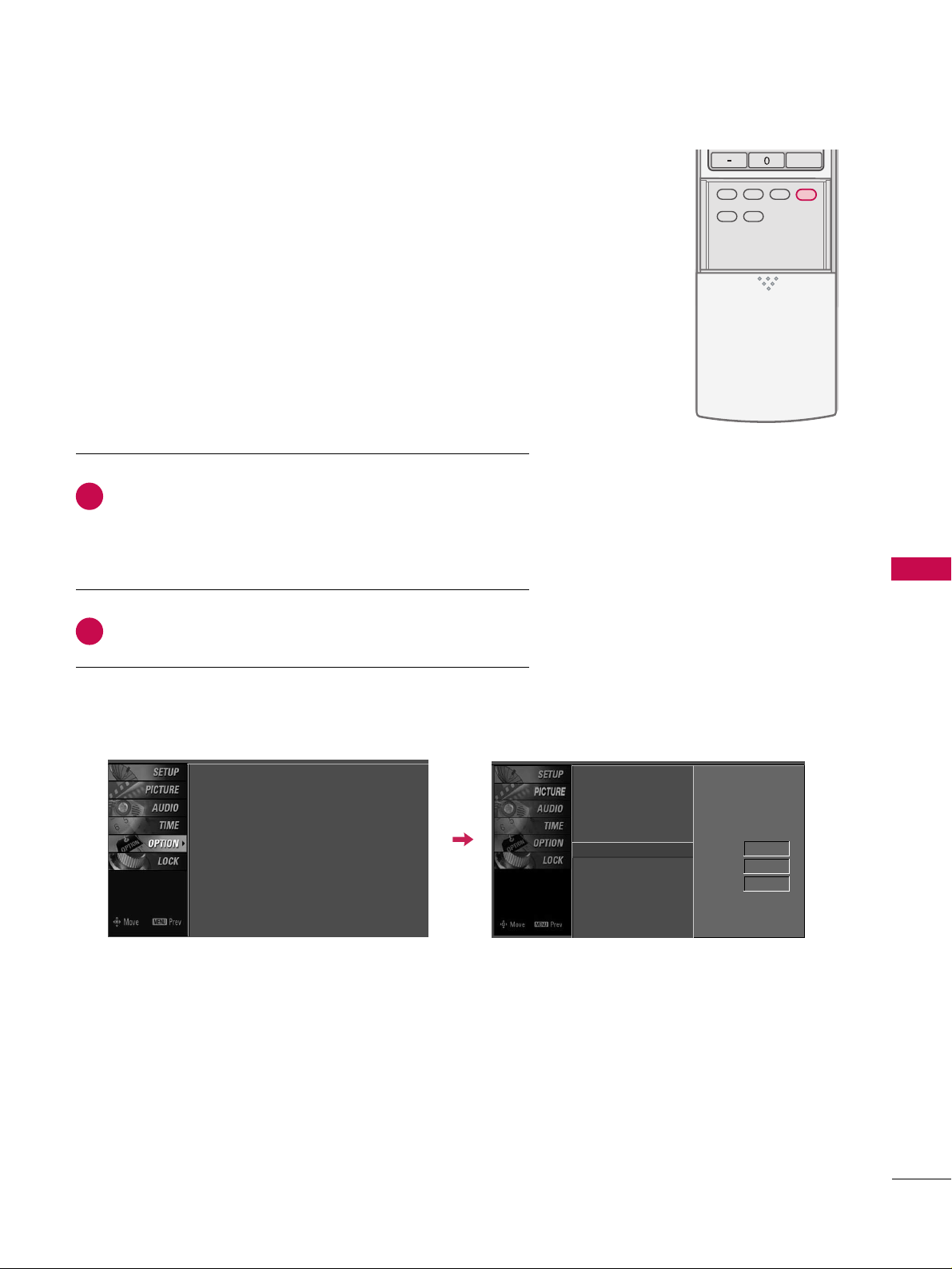
SOUND & LANGUAGE CONTROL
75
CAPTION MODE
TV INPUT
STB
BACKBACK
PICTUREPICTURE
SOUNDSOUND
SAPSAP
CC
MARKMARK
USB EJECTUSB EJECT
TV INPUT
STB
BACK
SOUND
SAP
CC
MARK
USB EJECT
TV INPUT
STB
BACK
PICTURE
SOUND
SAP
CC
MARK
USB EJECT
TV INPUT
STB
BACK
PICTURE
SOUND
SAP
CC
MARK
USB EJECT
TV INPUT
STB
BACK
PICTURE
SOUND
SAP
CC
MARK
USB EJECT
MEDIA HOST
MEDIA HOST
MEDIA HOST
MEDIA HOST
MEDIA HOST
Use the
CC CC
button to select Caption
OO nn
or
OO ffff
.
■
When selecting
OO ffff
,
Sub-menus for Analog, DTV, and
Digital Option become disabled.
Press
EEXXIITT
to save and return to TV viewing.
2
1
Caption must be provided to help people with hearing loss watch
TV.
■
You can also adjust
CCaapp ttiioonn
in the
OOPPTTIIOONN
menu.
Language : English
Input Label
SimpLink : Off
Key Lock : Off
Caption : Off
ISM Method : Orbiter
Low Power : Off
Front Display : Bright
Set ID : 1
Language
Input Label
SimpLink
Key Lock
Caption
G
ISM Method
Low Power
Front Display
Set ID
Mode On
Analog Text1
Digital Service3
Digital Option
Page 56
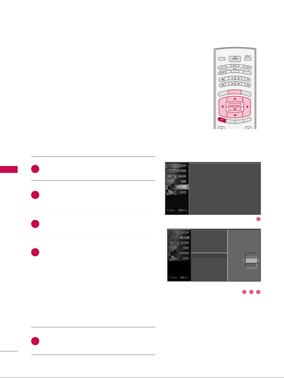
SOUND & LANGUAGE CONTROL
76
SOUND &LANGUAGE CONTROL
TV INPUTTV INPUT
STBSTB
BRIGHT +
BRI
G
H
T
-
T
I
M
E
R
R
A
T
I
O
S
I
M
P
LINK
M
E
N
U
TV INPUT
STB
TV INPUT
STB
TV INPUT
STB
TV INPUT
STB
MEDIA HOSTMEDIA HOST
MEDIA HOST
MEDIA HOST
MEDIA HOST
MEDIA HOST
Analog Broadcasting System Captions
Select a caption mode for displaying captioning information if
provided on a program. Analog caption displays information at
any position on the screen and is usually the program's dialog.
Caption/Text, if provided by the broadcaster, would be available
for both digital and analog channels on the Antenna/Cable.
This TV is programmed to memoririze the caption/text mode
which was last set when you turn the power off.
This function is only available when
CCaappttii oo nn
Mode is set
OO nn
.
Press the
MMEENNUU
button and then use
DD
or EEbutton
to select the
OO PPTTII OONN
menu.
Press the
GG
button and then useDDor EEbutton to
select
CCaappttiioo nn..
Press the
GG
button and then useDDor EEbutton to
select
AAnn aa lloogg..
Use
FF
or GGbutton to select
CCCC 11, CCCC 22, CCCC 33, CCCC 44
,
TTeexxtt 11, TTeexxtt 22, TTeexxtt 33
or
TTeexxtt 44
■
CCAAPP TT II OONN
The term for the words that scroll across the bottom of
the TV screen; usually the audio portion of the program
provided for the hearing impaired.
■
TTEEXXTT
The term for the words that appear in a large black
frame and almost cover the entire screen; usually messages provided by the broadcaster.
Press
EEXXIITT
button to return to TV viewing or press
MMEENN UU
button to return to the previous menu.
1
2
3
4
5
Language : English
Input Label
SimpLink : Off
Key Lock : Off
Caption : Off
ISM Method : Orbiter
Low Power : Off
Front Display : Bright
Set ID : 1
Language
Input Label
SimpLink
Key Lock
Caption
ISM Method
Low Power
Front Display
Set ID
Mode On
Analog Text1
Digital
Service3
Digital Option
1
3 42
Page 57

SOUND & LANGUAGE CONTROL
77
TV INPUTTV INPUT
STBSTB
BRIGHT +
BRI
G
H
T
-
T
I
M
E
R
R
A
T
I
O
S
I
M
P
LINK
M
E
N
U
TV INPUT
STB
TV INPUT
STB
TV INPUT
STB
TV INPUT
STB
MEDIA HOSTMEDIA HOST
MEDIA HOST
MEDIA HOST
MEDIA HOST
MEDIA HOST
Press the
MMEENNUU
button and then useDDor EEbutton
to select the
OO PPTTII OONN
menu.
Press the GGbutton and then useDDor EEbutton to
select
CCaapp ttiioonn
.
Press the
GG
button and then useDDor EEbutton to
select
DD iiggiittaall
.
Use
FF
or GGbutton to select
SS eerrvviiccee11~SS eerrvviiccee66
.
Press
EEXXIITT
button to return to TV viewing or press
MMEENN UU
button to return to the previous menu.
Choose the language you want the DTV/CADTV Captions
to appear in.
Other Languages can be chosen for digital sources only if
they are included on the program.
This function in only available when Caption Mode is set
On.
2
3
4
5
1
Digital Broadcasting System Captions
Language : English
Input Label
SimpLink : Off
Key Lock : Off
Caption : Off
ISM Method : Orbiter
Low Power : Off
Front Display : Bright
Set ID : 1
Language
Input Label
SimpLink
Key Lock
Caption
ISM Method
Low Power
Front Display
Set ID
Mode On
Analog Text1
Digital
Service3
Digital Option
1
3 42
Page 58

TV INPUTTV INPUT
STBSTB
BRIGHT +
BRI
G
H
T
-
T
I
M
E
R
R
A
T
I
O
S
I
M
P
LINK
M
E
N
U
TV INPUT
STB
TV INPUT
STB
TV INPUT
STB
TV INPUT
STB
MEDIA HOSTMEDIA HOST
MEDIA HOST
MEDIA HOST
MEDIA HOST
MEDIA HOST
SOUND & LANGUAGE CONTROL
78
SOUND &LANGUAGE CONTROL
Caption Option
Customize the DTV/CADTV captions that appear on your
screen.
This function in only available when Caption Mode is set
On.
Press the
MMEENNUU
button and then use
DD
or EEbutton
to select the
OO PPTTII OONN
menu.
Press the
GG
button and then useDDor EEbutton to
select
CCaapp ttiioonn
.
Press the GGbutton and then useDDor EEbutton to
select
DD iiggiittaall OOpptt iioonn
.
Press the
GG
button and then useFFor GGbutton to
select
CCuusstt oomm
.
Use
DD
or EEbutton to customize the
SS ttyyllee, FFoo nntt
, etc.,
to your preference.
A preview icon is provided at the bottom of the screen,
use it to see the caption language.
■
SSiizzee
: Set the word size.
■
FFoonntt
: Select a typeface for the text.
■
TTeexxtt CCoolloorr
: Choose a color for the text.
■
TTeexxtt OOppaacciittyy
: Specify the opacity for the text color.
■
BBgg ((BBaacckkggrroouunndd))CCoolloorr
: Select a background color.
■
BBgg ((BBaacckkggrroouunndd))OOppaacciittyy
: Select the opacity for
the background color.
■
EEddggee TTyyppee
: Select an edge type.
■
ddggee CCoolloorr
: Select a color for the edges.
Press
EEXXIITT
button to return to TV viewing or press
MMEENN UU
button to return to the previous menu.
2
3
4
5
6
1
Language
Input Label
SimpLink
Key Lock
Caption
ISM Method
Low Power
Front Display
Set ID
Mode On
Analog Text1
Digital Service3
Digital Option
G
Selection ( Gor ) leads you to the
Caption Option screen.
Language : English
Input Label
SimpLink : Off
Key Lock : Off
Caption : Off
ISM Method : Orbiter
Low Power : Off
Front Display : Bright
Set ID : 1
Language
Input Label
SimpLink
Key Lock
Caption
ISM Method
Low Power
Front Display
Set ID
Mode On
Analog Text1
Digital Service3
Digital Option
G
Style Custom
Size A Standard
Font Font 0
Text Color White
Text Opacity
Solid
Bg Color Black
Bg Opacity Solid
Edge Type None
Edge Color Black
Selection ( Gor ) leads you to the
Caption Option screen.
1
32
54
Page 59

SOUND & LANGUAGE CONTROL
79
CLOCK SETTING
TIME SETTING
TV INPUTTV INPUT
STBSTB
BRIGHT +
BRI
G
H
T
-
T
I
M
E
R
R
A
T
I
O
S
I
M
P
LINK
M
E
N
U
TV INPUT
STB
TV INPUT
STB
TV INPUT
STB
TV INPUT
STB
MEDIA HOSTMEDIA HOST
MEDIA HOST
MEDIA HOST
MEDIA HOST
MEDIA HOST
Auto Clock Setup
The time is set automatically from a digital channel signal.
The digital channel signal includes information for the
current time provided by the broadcasting station.
Set the clock manually if the current time is set incorrectly
by the auto clock function.
Press the
MMEENNUU
button and then use
DD
or EEbutton
to select the
TTII MM EE
menu.
Press the GGbutton and then useDDor EEbutton to
select
CCll oocckk
.
Press the
GG
button and then useDDor EEbutton to
select
AAuu ttoo
.
Press the
GG
button and then useDDor EEbutton to
select your viewing area time zone:
U.S.A :
EEaasstt eerr nn, CCee nntt rr aall, MMoo uunn ttaa iinn, PP aacc iiffiicc
,
AAllaasskkaa
or
HH aa wwaaii ii
.
Canada :
EEaass tt ee rr nn, CCeenntt rr aa ll, MMoo uu nn ttaa iinn, PP aacc iiffii cc
,
NNeeww FF ..llaanndd
or
AAttllaannttii cc
.
Press the
GG
button and then useDDor EEbutton to
select
AAuu ttoo, OO ffff, OO nn
, depending on whether or not
your viewing area observes Daylight Saving time.
Press
EEXXIITT
button to return to TV viewing or press
MMEENN UU
button to return to the previous menu.
2
3
4
5
6
1
Clock
G
Off Time
On Time
Sleep Time
Auto Sleep
Time Zone Eastern
Auto
Daylight
Saving
Clock : Oct 19, 2006, 03:44 AM
Off Time : Off
On Time : Off
Sleep Time : Off
Auto Sleep : Off
Year - - - Date - - / - Time - - : - - - -
Auto
Clock
G
Off Time
On Time
Sleep Time
Auto Sleep
Auto
Year - - - Date - - / - Time - - : - - - -
Auto
Time Zone Eastern
Daylight
Saving
DD
EE
G
DD
EE
G
1
32
54
Page 60

TIME SETTING
80
TV INPUTTV INPUT
STBSTB
BRIGHT +
BRI
G
H
T
-
T
I
M
E
R
R
A
T
I
O
S
I
M
P
LINK
M
E
N
U
TV INPUT
STB
TV INPUT
STB
TV INPUT
STB
TV INPUT
STB
MEDIA HOSTMEDIA HOST
MEDIA HOST
MEDIA HOST
MEDIA HOST
MEDIA HOST
Manual Clock Setup
If the current time setting is wrong, reset the clock manually.
Press the
MMEENNUU
button and then use
DD
or EEbutton
to select the
TTII MM EE
menu.
Press the GGbutton and then useDDor EEbutton to
select
CCll oocckk
.
Press the
GG
button and then useDDor EEbutton to
select
MMaannuuaall
.
Press the
GG
button and then useFFor GGbutton to
select either the year, date, or time option. Once
selected, use the
DD
or EEbutton to set the year, date,
and time options.
Press
EEXXIITT
button to return to TV viewing or press
MMEENN UU
button to return to the previous menu.
2
3
4
5
1
Clock
G
Off Time
On Time
Sleep Time
Auto Sleep
Clock : Oct 19, 2007, 03:44 AM
Off Time : Off
On Time : Off
Sleep Time : Off
Auto Sleep : Off
Year - - - Date - - / - Time - - : - - - -
Manual
DD
EE
G
1
32
Page 61
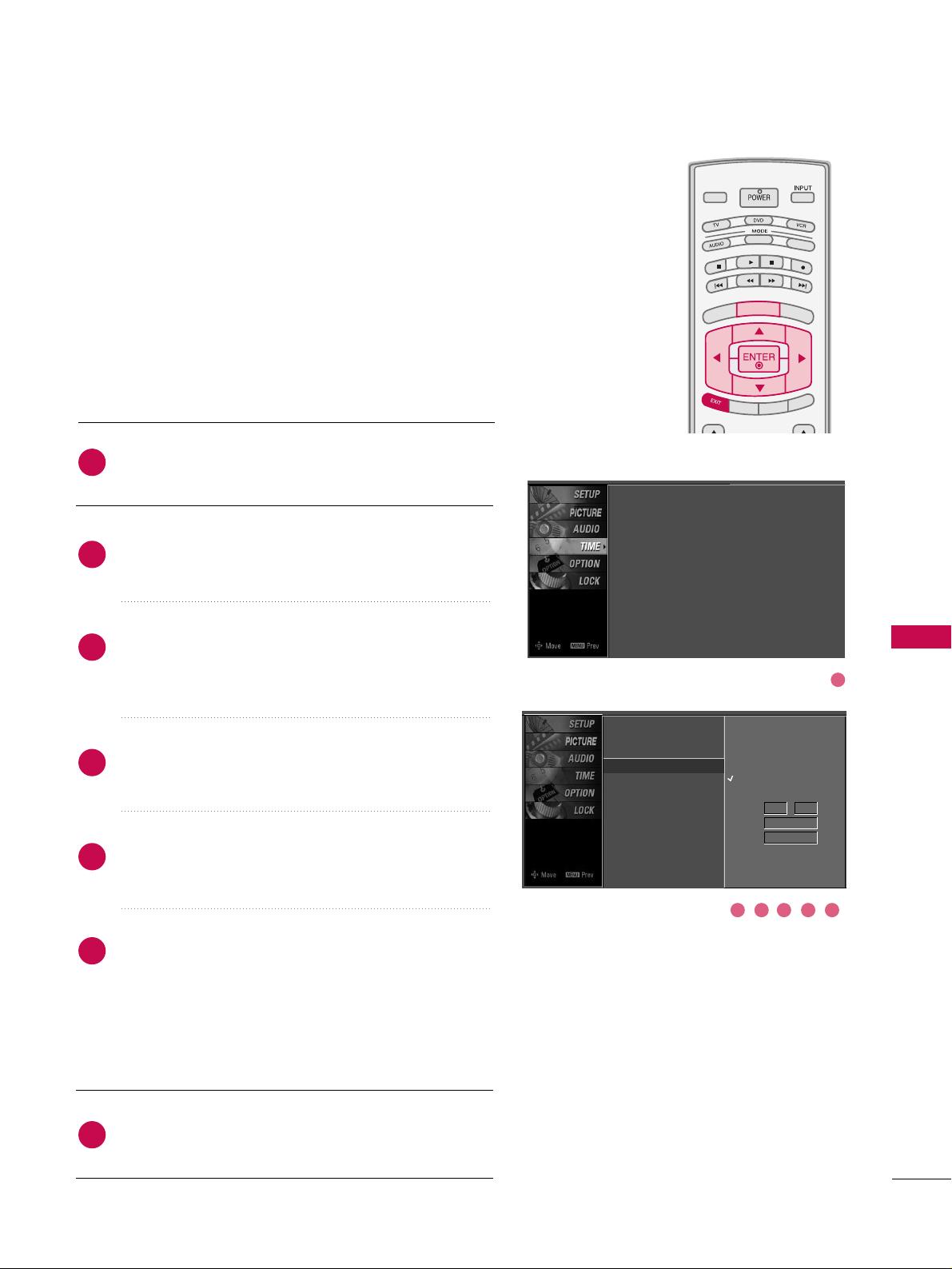
TIME SETTING
81
AUTO ON/OFF TIMER SETTING
TV INPUTTV INPUT
STBSTB
BRIGHT +
BRI
G
H
T
-
T
I
M
E
R
R
A
T
I
O
S
I
M
P
LINK
M
E
N
U
TV INPUT
STB
TV INPUT
STB
TV INPUT
STB
TV INPUT
STB
MEDIA HOSTMEDIA HOST
MEDIA HOST
MEDIA HOST
MEDIA HOST
MEDIA HOST
This function operates only if the current time has been set.
The
OOff ff TT ii mmee
function overrides the
OOnn TTiimmee
function if
they are both set to the same time.
The TV must be in standby mode for the
OOnn TT iimm ee
to work.
If you do not press any button within 2 hours after the TV
turns on with the
OOnn TTiimm ee
function, the TV will automati-
cally revert to standby mode.
Press the
MMEENNUU
button and then use
DD
or EEbutton
to select the
TTII MM EE
menu.
Press the
GG
button and then useDDor EEbutton to
select
OO ffff TTiimm ee
or
OO nn TTiimmee
.
Press the GGbutton and then useDDor EEbutton to
select
OO nn
.
■
To cancel the
OO nn//OOffff ttii mmee
function, select
OO ffff
.
Press the
GG
button and then useDDor EEbutton to the
hour.
Press the GGbutton and then useDDor EEbutton to the
minutes.
OOnnllyy OOnn TTiimm ee
Press the
GG
button and then useDDor EEbutton to
select the channel at turn-on.
Press the
GG
button and then useDDor EEbutton to the
sound level at turn-on.
Press
EEXXIITT
button to return to TV viewing or press
MMEENN UU
button to return to the previous menu.
2
3
4
5
6
7
1
Clock
Off Time
On Time
G
Sleep Time
Auto Sleep
Off
On
Time 6 : 30 AM
Ch. TV 2-0
Vol 17
Clock : Oct 19, 2007, 03:44 AM
Off Time : Off
On Time : Off
Sleep Time : Off
Auto Sleep : Off
1
32 54 6
Page 62

TIME SETTING
82
TIME SETTING
SLEEP TIMER SETTING
TV INPUTTV INPUT
STBSTB
M
E
N
U
B
R
I
G
H
T +
BRI
G
HT
-
RAT
I
O
S
I
MP
L
IN
K
TV INPUT
STB
TV INPUT
STB
T
I
M
E
RT
I
M
E
R
MEDIA HOSTMEDIA HOST
MEDIA HO
ST
MEDIA HOST
The Sleep Time turns the TV off at the preset time.
Note that this setting is cleared when the TV is turned off.
Press the
TTII MM EERR
button repeatedly to select the number of
minutes. First the
OO ffff
option appears on the screen, followed
by the following sleep time options : 10, 20, 30, 60, 90, 120,
180, and 240 minutes.
When the number of minutes you want is displayed on the
screen, press the
EENNTTEERR
button. The timer begins to count
down from the number of minutes selected.
To check the remaining minutes before the TV turns off, press
the
TTII MM EERR
button once.
To cancel the Sleep Time, press the
TTIIMMEERR
button repeatedly
to select
OO ffff
.
■
You can also set up the
SS lleeeepp TTii mmee
in the
TTII MM EE
menu.
2
3
4
1
Clock
Off Time
On Time
Sleep Time
G
Auto Sleep
Off
10 min
20 min
30 min
60 min
90 min
120 min
180 min
240 min
Clock : Oct 19, 2006, 03:44 AM
Off Time : Off
On Time : Off
Sleep Time : Off
Auto Sleep : Off
Page 63

TIME SETTING
83
AUTO SHUT-OFF SETTING
TV INPUTTV INPUT
STBSTB
BRIGHT +
BRI
G
H
T
-
T
I
M
E
R
R
A
T
I
O
S
I
M
P
LINK
M
E
N
U
TV INPUT
STB
TV INPUT
STB
TV INPUT
STB
TV INPUT
STB
MEDIA HOSTMEDIA HOST
MEDIA HOST
MEDIA HOST
MEDIA HOST
MEDIA HOST
TV will be automatically turned off, in case of No Signal for
10 m i n u t e s .
Press the
MMEENNUU
button and then useDDor EEbutton
to select the
TTII MM EE
menu.
Press the
GG
button and then useDDor EEbutton to
select
AAuu ttoo SS lleeeepp
.
Press the
GG
button and then useDDor EEbutton to
select
OO nn
or
OO ffff
.
Press
EEXXIITT
button to return to TV viewing or press
MMEENN UU
button to return to the previous menu.
2
3
4
1
Clock
Off Time
On Time
Sleep Time
Auto Sleep
G
Off
On
TV will be automatically turned
off, in case of No Signal for 10
minutes.
Clock : Oct 19, 2007, 03:44 AM
Off Time : Off
On Time : Off
Sleep Time : Off
Auto Sleep : Off
1
32
Page 64

PARENTAL CONTROL / RATING
84
PARENTAL CONTROL / RATINGS
Parental Control can be used to block specific channels, ratings and other viewing sources.
The Parental Control Function (V-Chip) is used to block program viewing based on the ratings
sent by the broadcasting station. The default setting is to allow all programs to be viewed.
Viewing can be blocked by choosing the type of the program and the categories. It is also possible to block all program viewing for a time period. To use this function, the following must be
done :
1. Set ratings and categories to be blocked.
2. Specify a password
3. Enable the lock
V-Chip rating and categories
Rating guidelines are provided by broadcasting stations. Most television programs and television
movies can be blocked by TV Rating and/or Individual Categories. Movies that have been shown
at the theaters or direct-to-video movies use the Movie Rating System (MPAA)only.
Ratings for Television programs including made-for-TV movies :
■
TV-G(General audience
)
■
TV-PG(Parental guidance suggested
)
■
TV-14(Parents strongly cautioned
)
■
TV-MA (Mature audience only
)
■
TV-Y(All children
)
■
TV-Y7(Children 7 years older
)
SET PASSWORD & LOCK SYSTEM
Set up blocking schemes to block specific channels, ratings, and
external viewing sources.
A password is required to gain access to this menu.
Press the
MMEENNUU
button and then use the
DD
or EEbutton
to select the
LLOOCC KK
menu. Then, press the
GG
button.
■
Enter the password as requested.
■
The TV is set up with the initial
password “0-0-0-0”.
TV INPUT
STB
BRIGHT +
BRI
G
H
T
-
T
I
M
E
R
R
A
T
I
O
S
I
M
P
LINK
M
E
N
U
TV INPUT
STB
TV INPUT
STB
TV INPUT
STB
TV INPUT
STB
MEDIA HOST
MEDIA HOST
MEDIA HOST
MEDIA HOST
MEDIA HOST
Enter Password
1
Enter Password
** **
Setting up Your Password
Page 65

PARENTAL CONTROL / RATING
85
After inputting the password, use theDDor EEbutton
to choose
SS eett pp aasssswwoo rrdd
.
Press the
GG
button and then choose any 4 digits for
your new password.
As soon as the 4 digits are entered, re-enter the same
4 digits on the
CCoonnffii rrmm
.
Then your changed password has been memorized.
Press
EEXXIITT
button to return to TV viewing or press
MMEENN UU
button to return to the previous menu.
Change the password by inputting a new password twice.
Lock System
Set Password
G
Block Channel
Movie Rating
TV Rating-Children
TV Rating-General
Input Block
New
Confirm
2
3
1
****
****
Lock System : Off
Set Password
Block Channel
Movie Rating
TV Rating-Children
TV Rating-General
Input Block
Lock System : Off
Set Password
Block Channel
TV Rating-English
TV Rating-French
Input Block
For USA For Canada
After inputting the password, use the
DD
or EEbutton
to choose
LLoo cc kk SSyysstt eemm
.
Press the
GG
button and then use theDDor EEbutton
to select
OO nn
or
OO ffff
.
■
When you select
OO nn
, the Lock System is enable.
Press
EEXXIITT
button to return to TV viewing or press
MMEENN UU
button to return to the previous menu.
Enables or disables the blocking scheme you set up previously.
Lock System
G
Set Password
Block Channel
Movie Rating
TV Rating-Children
TV Rating-General
Input Block
Off
On
Lock System : Off
Set Password
Block Channel
Movie Rating
TV Rating-Children
TV Rating-General
Input Block
2
3
1
Lock System : Off
Set Password
Block Channel
TV Rating-English
TV Rating-French
Input Block
For USA For Canada
Set Password
Lock System
1
2
1
2
Page 66

PARENTAL CONTROL / RATING
86
CHANNEL BLOCKING
PARENTAL CONTROL /RATINGS
EXTERNAL INPUT BLOCKING
Blocks any channels that you do not want to watch or that
you do not want your children to watch.
After inputting the password, use the
DD
or EEbutton
to choose
BBlloo cckk CC hhaannnneell
.
Press the
GG
button. You will now see a screen filled
with channel numbers and a preview picture.
Use
DD EE FF GG
button to select a channel and then
use the
EENNTTEERR
button to block or unblock it.
Press
EEXXIITT
button to return to TV viewing or press
MMEENNUU
button to return to the previous menu.
Lock System
Set Password
Block Channel
G
Movie Rating
TV Rating-Children
TV Rating-General
Input Block
Selection ( Gor ) leads you to the
block channel screen.
2
3
4
1
Enables you to select a source to block from the external
source devices you have hooked up.
After inputting the password, use the
DD
or EEbutton
to choose
II nnppuutt BBlloo cckk
.
Press the
GG
button and then use theDDor EEbutton
to select a source.
Use the
FF
or GGbutton to select
OO nn
or
OO ffff
on the
each source.
Press
EEXXIITT
button to return to TV viewing or press
MMEENNUU
button to return to the previous menu.
Lock System
Set Password
Block Channel
Movie Rating
TV Rating-Children
TV Rating-General
Input Block
G
AV1 On
AV2 On
Component1 Off
Component2 On
RGB-PC
Off
HDMI1 Off
HDMI2 Off
HDMI3 Off
2
3
4
1
Lock System : Off
Set Password
Block Channel
Movie Rating
TV Rating-Children
TV Rating-General
Input Block
Lock System : Off
Set Password
Block Channel
TV Rating-English
TV Rating-French
Input Block
For USA For Canada
1
32
1
32
Page 67

PARENTAL CONTROL / RATING
87
MOVIE & TV RATING
TV INPUTTV INPUT
STBSTB
BRIGHT +
BRI
G
H
T
-
T
I
M
E
R
R
A
T
I
O
S
I
M
P
LINK
M
E
N
U
TV INPUT
STB
TV INPUT
STB
TV INPUT
STB
TV INPUT
STB
MEDIA HOSTMEDIA HOST
MEDIA HOST
MEDIA HOST
MEDIA HOST
MEDIA HOST
Movie Rating (MPAA)
-
for USA only
Blocks movies according to the movie ratings limits specified, so children cannot view certain movies. You can set
the ratings limit by blocking out all the movies with the
ratings above a specified level. Keep in mind that the
movie ratings limit only applies to movies shown on TV,
not TV programs, such as soap operas.
After inputting the password, use the
DD
or EEbutton
to choose
MMoovv iiee RRaatt iinngg
.
Press the GGbutton and then use theDDor EEbutton
to select GG,
PP GG, PP GG-- 1133, RR, NNCC --11 77
or XX.
■
G (General audience)
■
PG (Parental guidance suggested)
■
PG-13 (Parents strongly cautioned)
■
R (Restricted)
■
NC-17 (No one 17 and under admitted)
■
X (Adult only)
■
Blocking Off (Permits all programs)
Press
EEXXIITT
button to return to TV viewing or press
MMEENNUU
button to return to the previous menu.
GG
If you set PG-13 : G and PG movies will be available,
PG-13, R, NC-17 and X will be blocked.
Lock System
Set Password
Block Channel
Movie Rating
G
TV Rating-Children
TV Rating-General
Input Block
Blocking off : permits all
programs
G
PG
PG-13
R
NC-17
X
Blocking Off
2
3
1
1
2
Lock System : Off
Set Password
Block Channel
Movie Rating
TV Rating-Children
TV Rating-General
Input Block
Page 68

PARENTAL CONTROL / RATING
88
PARENTAL CONTROL /RATINGS
TV Rating Children
-
for USA only
After inputting the password, use theDDor EEbutton to
choose
TTVV RRaatt iinn gg--CChhiill ddrreenn
.
Press the
GG
button and then use theDDor EEbutton to
select
AAggee
, or
FFaann ttaass yy VViioolleennccee
.
Press the
GG
button and then use theDDor EEbutton to
select block options.
■
Age(applies to TV-Y, TV-Y7)
■
Fantasy Violence(applies to TV-Y7)
Press
EEXXIITT
button to return to TV viewing or press
MMEENNUU
button to return to the previous menu.
Prevents children from watching certain children's TV programs, according to the ratings limit set. The children rating
does not apply to other TV programs. Unless you block certain TV programs intended for mature audiences in the TV
Rating - sub menu, your children can view those programs.
TV Rating General
-
for USA only
After inputting the password, use theDDor EEbutton to
choose
TTVV RRaatt iinn gg--GGeenneerraall
.
Press the
GG
button and then use theDDor EEbutton to
select
AAggee, DD iiaalloogguuee, LLaanngguuaa ggee, SS eexx
or
VViioo lleenn ccee
.
Press the
GG
button and then use theDDor EEbutton to
select block options.
■
Age(applies to TV-G,TV-PG,TV-14,TV-MA)
■
Dialogue-sexual dialogue (applies to TV-PG,TV-14)
■
Language-adult language (applies to TV-PG,TV-14,TV-MA)
■
Sex-sexual situations (applies to TV-PG,TV-14,TV-MA)
■
Violence (applies to TV-PG,TV-14,TV-MA)
Press
EEXXIITT
button to return to TV viewing or press
MMEENNUU
button to return to the previous menu.
Based on the ratings, blocks certain TV programs that you
and your family do not want to view.
Lock System
Set Password
Block Channel
Movie Rating
TV Rating-Children
G
TV Rating-General
Input Block
Age
Fantasy Violence
Lock System
Set Password
Block Channel
Movie Rating
TV Rating-Children
TV Rating-General
G
Input Block
Age
Dialogue
Language
Sex
Violence
2
3
1
2
3
1
1
2
1
2
Lock System : Off
Set Password
Block Channel
Movie Rating
TV Rating-Children
TV Rating-General
Input Block
Lock System :
Off
Set Password
Block Channel
Movie Rating
TV Rating-Children
TV Rating-General
Input Block
Page 69

PARENTAL CONTROL / RATING
89
TV Rating English
-
for CANADA only
After inputting the password, use theDDor EEbutton to
choose
TTVV RRaatt iinn gg--EEnn gglliisshh
.
Press the
GG
button and then use theDDor EEbutton to
select EE, CC,
CC88 ++, GG, PP GG, 11 44++, 11 88++
, or
BBlloocckkiinngg OOffff
.
■
E (Exempt)
■
C (Children)
■
C8+ (Children eight years and older)
■
G (General programming, suitable for all audiences)
■
PG (Parental Guidance )
■
14+ (Viewers 14 years and older)
■
18+ (Adult programming)
■
Blocking Off (Permits all programs)
Press
EEXXIITT
button to return to TV viewing or press
MMEENNUU
button to return to the previous menu.
Selecting canadian english language rating system.
TV Rating French
-
for CANADA only
After inputting the password, use theDDor EEbutton
to choose
TTVV RRaatt iinn gg--FFrreenn cchh
.
Press the
GG
button and then use theDDor EEbutton
to select EE, GG,
88 aa nnss ++, 1133aannss++, 1166aannss++, 1188aannss++
,
or
BBlloo cckkii nngg ooff ff
.
■
E(Exempt)
■
G(General)
■
8ans+ (General-Not convenient for little children)
■
13ans+ (Not convenient for children of 13 years
and younger)
■
16ans+ (Not convenient for children of 16 years
and younger)
■
18ans+ (This programs is only for adults)
■
Blocking off (Permits all programs)
Press
EEXXIITT
button to return to TV viewing or press
MMEENNUU
button to return to the previous menu.
Selecting canadian french language rating system.
Lock System
Set Password
Block Channel
TV Rating-English
G
TV Rating-French
Input Block
Lock System
Set Password
Block Channel
TV Rating-English
TV Rating-French
G
Input Block
2
3
1
2
3
1
Blocking off : permits all
programs
E
C
C8+
G
PG
14+
18+
Blocking Off
Blocking off : permits all
programs
E
G
8 ans+
13 ans+
16 ans+
18 ans+
Blocking Off
1
2
1
2
Lock System : Off
Set Password
Block Channel
TV Rating-English
TV Rating-French
Input Block
Page 70

APPENDIX
90
APPENDIX
TROUBLESHOOTING
TThhee ooppeerraattiioonn ddooeess nnoott wwoorrkk nnoorrmmaallllyy..
TThhee vviiddeeoo ffuunnccttiioonn ddooeess nnoott wwoorrkk..
No picture &No sound
No or poor color
or poor picture
Poor reception on
some channels
Lines or streaks
in pictures
Horizontal/vertical bars
or picture shaking
Picture appears slowly
after switching on
The remote control
doesn’t work
Power is suddenly
turned off
■
Check to see if there is any object between the product and the remote control
causing obstruction. Ensure you are pointing the remote control directly at the TV.
■
Ensure that the batteries are installed with correct polarity (+ to +, - to -).
■
Ensure that the correct remote operating mode is set: TV, VCR etc.
■
Install new batteries.
■
Is the sleep timer set?
■
Check the power control settings. Power interrupted.
■
No broadcast on station tuned with Auto off activated.
■
Check whether the product is turned on.
■
Try another channel. The problem may be with the broadcast.
■
Is the power cord inserted into wall power outlet?
■
Check your antenna direction and/or location.
■
Test the wall power outlet, plug another product’s power cord into the outlet
where the product’s power cord was plugged in.
■
This is normal, the image is muted during the product startup process. Please
contact your service center, if the picture has not appeared after five minutes.
■
Adjust Color in menu option.
■
Keep a sufficient distance between the product and the VCR.
■
Try another channel. The problem may be with the broadcast.
■
Are the video cables installed properly?
■
Activate any function to restore the brightness of the picture.
■
Check for local interference such as an electrical appliance or power tool.
■
Station or cable product experiencing problems, tune to another station.
■
Station signal is weak, reorient antenna to receive weaker station.
■
Check for sources of possible interference.
■
Check antenna (Change the direction of the antenna).
Page 71

APPENDIX
91
TThheerree iiss aa pprroobblleemm iinn PPCC mmooddee.. ((OOnnllyy PPCC mmooddee aapppplliieedd))
■
Adjust resolution, horizontal frequency, or vertical frequency.
■
Check the input source.
■
Work the Auto configure or adjust clock, phase, or H/V position. (Option)
■
Check the signal cable.
■
Reinstall the PC video card.
The signal is out of range
Screen color is unstable
or single color
Vertical bar or stripe on
background &
Horizontal Noise &
Incorrect position
■
Press the VOL or VOLUME button.
■
Sound muted? Press MUTE button.
■
Try another channel. The problem may be with the broadcast.
■
Are the audio cables installed properly?
■
Adjust Balance in menu option.
■
A change in ambient humidity or temperature may result in an unusual noise
when the product is turned on or off and does not indicate a fault with the
product.
Picture OK & No sound
Unusual sound from
inside
the product
No output from one
of the speakers
TThhee aauuddiioo ffuunnccttiioonn ddooeess nnoott wwoorrkk..
Page 72

APPENDIX
92
MAINTENANCE
APPENDIX
Early malfunctions can be prevented. Careful and regular cleaning can extend the amount of time you can
enjoy your new TV.
Caution: Be sure to turn the power off and unplug the power cord before you begin any cleaning.
Cleaning the Screen
Here’s a great way to keep the dust off your screen for a while. Wet a soft cloth in a mixture of lukewarm
water and a little fabric softener or dish washing detergent. Wring the cloth until it’s almost dry, and then
use it to wipe the screen.
Make sure the excess water is off the screen, and then let it air-dry before you turn on your TV.
Cleaning the Cabinet
■
To remove dirt or dust, wipe the cabinet with a soft, dry, lint-free cloth.
■
Please be sure not to use a wet cloth.
Extended Absence
GG
If you expect to leave your TV dormant for a long time (such as a vacation), it’s a good idea to unplug
the power cord to protect against possible damage from lightning or power surges.
CAUTION
2
1
Page 73

APPENDIX
93
PRODUCT SPECIFICATIONS
■
The specifications shown above may be changed without prior notice for quality improvement.
47LC7DF
(47LC7DF-UK)
50PY3D
(50PY3DF-UJ)
60PY3D
(60PY3DF-UJ)
MODELS
45.1 x 32.5x 12.1 inches
1144.3 x 825.5 x 306.4mm
45.1 x 29.7 x 4.1 inches
1144.3 x 754.7 x 103.0 mm
82.9 pounds / 37.6 kg
69.4 pounds / 31.5 kg
53.5 x 35.0 x 14.6 inches
1360.0 x 887.0 x 370.0 mm
53.5 x 32.4 x 3.8 inches
1360.0 x 822.8 x 95.5 mm
126.8 pounds / 57.5kg
107.0 pounds / 48.5kg
63.5 x 40.8 x 17.8 inches
1613.6 x 1036.8 x 452.0 mm
63.5 x 38.2 x 3.9 inches
1613.6 x 970.0 x 98.5 mm
178.6 pounds / 81.0kg
143.3 pounds / 65.0kg
AC100-240V ~ 50/60Hz
NTSC-M, ATSC, 64 & 256 QAM
VHF 2-13, UHF 14-69, CATV 1-135, DTV 2-69, CADTV 1-135
75 ohm
32 ~ 104°F (0 ~ 40°C)
Less than 80%
-4 ~ 140°F (-20 ~ 60°C)
Less than 85%
Dimensions
(Width x Height x Depth)
Weight
Power requirement
Television System
Program Coverage
External Antenna Impedance
Environment condition
Including stand
Excluding stand
including stand
excluding stand
Operating Temperature
Operating Humidity
Storage Temperature
Storage Humidity
Page 74

APPENDIX
94
APPENDIX
37LB5D
(37LB5DF-UL)
42LB5D
(42LB5DF-UL)
47LB5D
(47LB5DF-UL)
52LB5D
(52LB5DF-UL)
MODELS
36.5 x 27.3 x 11.1 inches
927.0 x 692.8 x 283.2 mm
36.5 x 24.8 x 3.5 inches
927.0 x 630.0 x 88.0 mm
44.1 pounds / 20.0kg
35.3 pounds / 16.0kg
40.7 x 29.5 x 11.3 inches
1033.1 x 750.0 x 287.6 mm
40.7 x 27.0 x 3.5 inches
1033.1 x 686.5 x 88.5 mm
60.6 pounds / 27.5kg
50.7 pounds / 23.0kg
45.1 x 32.5 x 13.0 inches
1144.5 x 825.6 x 331.0 mm
45.1 x 29.7 x 4.1 inches
1144.5 x 754.9 x 103.0 mm
82.7 pounds / 37.5kg
69.2 pounds / 31.4kg
50.6 x 35.5 x 14.1 inches
1284.6 x 901.8 x 356.9 mm
50.6 x 32.7 x 4.4 inches
1284.6 x 831.6 x 111.5 mm
106.0 pounds / 48.1kg
89.3 pounds / 40.5kg
AC100-240V ~ 50/60Hz
NTSC-M, ATSC, 64 & 256 QAM
VHF 2-13, UHF 14-69, CATV 1-135, DTV 2-69, CADTV 1-135
75 ohm
32 ~ 104°F (0 ~ 40°C)
Less than 80%
-4 ~ 140°F (-20 ~ 60°C)
Less than 85%
Dimensions
(Width x Height
x Depth)
Weight
Power requirement
Television System
Program Coverage
External Antenna Impedance
Environment
condition
Including stand
Excluding stand
including stand
excluding stand
Operating Temperature
Operating Humidity
Storage Temperature
Storage Humidity
Page 75

APPENDIX
95
PROGRAMMING THE REMOTE CONTROL
The provided universal remote control can be programmed to operate most remote-controllable devices.
Note that the remote may not control all models of other brands.
Programming a code into a remote mode
To find out whether your remote control can operate each device without programming, turn on the device
(such as a VCR) and press the corresponding mode button on the remote.
After that, press the
PPOOWWEERR
button. If the device is turned off and it responds properly the remote control
need not be programmed. If not, the remote should be programmed to operate the device. The programming procedures are explained below.
Press the
MMEENNUU
and
MMUUTTEE
button continuously at the same time for two seconds; the currently selected
device button is illuminated.
If you don't press any button for 20 seconds, the light on the mode button will be turned off. In that case,
you have to repeat from step 2.
Enter the appropriate code from the code table on the following pages. When pressing the button, the
light blinks at a time. If the device turned off, the programming is successful.
Press the
MMEENNUU
button to store the code. After blinking twice, this code is stored.
Test the remote control functions to see if the device responds properly. If not, steps 2-5.
2
3
4
5
1
Page 76

APPENDIX
96
Remote Control Code
APPENDIX
Brand Codes Brand Codes Brand Codes
AIWA 034
AKAI 016 043 046 124
12 5 14 6
AMPRO 072
ANAM 031 033 103
AUDIO DYNAMICS
012 0 23 039 0 43
BROKSONIC 035 037 129
CANON 028 031 033
CAPEHART 108
CRAIG 003 040 135
CURTIS MATHES 031 033 041
DAEWOO 005 007 010 064
0 6 5 10 8 110 111
112 116 117 119
DAYTRON 108
DBX 012 023 039 043
DYNATECH 034 053
ELECTROHOME 059
EMERSON 006 017 025 027
029 031 034 035
036 037 046 101
12 9 131 138 15 3
FISHER 003 008 009 010
FUNAI 034
GE 031 033 063 072
10 7 109 144 147
GO VIDEO 132 136
HARMAN KARDON 012 045
HITACHI 004 018 026 034
043 063 137 150
INSTANTREPLAY 031 033
JCL 031 033
JCPENNY 012 013 015 033
040 066 101
JENSEN 043
JVC 012 031 033 043
048 050 055 060
13 0 15 0 15 2
KENWOOD 014 034 039 043
047 048
LG (GOLDSTAR) 001 012 013 020
101 10 6 114 123
LLOYD 034
LXI 003 009 013 014
017 0 34 101 106
MAGIN 040
MAGNAVOX 031 033 034 041
067 068
MARANTZ 012 031 033 067
069
MARTA 101
MATSUI 027 030
MEI 031 033
MEMOREX 003 010 014 031
033 034 053 072
101 10 2 134 139
MGA 045 046 059
MINOLTA 013 020
MITSUBISHI 013 020 045 046
049 051 059 061
151
MTC 034 040
MULTITECH 024 034
NEC 012 023 039 043
048
NORDMENDE 043
OPTONICA 053 054
PANASONIC 066 070 074 083
13 3 14 0 14 5
PENTAX 013 020 031 033
063
PHILCO 031 034 067
PHILIPS 031 033 034 054
067 071 101
PILOT 101
PIONEER 013 021 048
PORTLAND 108
PULSAR 072
QUARTZ 011 014
QU ASA R 033 066 075 145
RCA 013 020 033 034
040 041 062 063
107 109 140 144
14 5 147
REALISTIC 003 008 010 014
031 033 034 040
053 054 101
RICO 058
RUNCO 148
SALORA 014
SAMSUNG 032 040 102 104
10 5 107 10 9 112
113 115 12 0 12 2
12 5
SANSUI 022 043 048 135
SANYO 003 007 010 014
10 2 13 4
SCOTT 017 037 112 129
131
SEARS 003 008 009 010
013 014 017 02 0
031 0 42 073 081
101
SHARP 031 054 149
SHINTOM 024
SONY 003 009 031 052
056 057 058 076
077 078 149
SOUNDESIGN 034
STS 013
SY LVA NI A 031 033 034 059
067
SYMPHONIC 034
TANDY 010 034
TATUNG 039 043
TEA C 034 039 043
TECHNICS 031 033 070
TEKNIKA 019 031 033 034
101
THOMAS 034
TMK 006
TOSHIBA 008 013 042 047
059 082 112 131
TOTEVISION 040 101
UNITECH 040
VECTOR RESEARCH
012
VICTOR 048
VIDEO CONCEPTS
012 0 34 04 6
VIDEOSONIC 040
WARDS 003 013 017 024
031 033 034 040
053 054 131
YAMAHA 012 034 039 043
ZENITH 034 048 056
058 072 080 101
VCR
Page 77

APPENDIX
97
Cable Box
Brand Codes Brand Codes Brand Codes
Brand Codes Brand Codes Brand Codes
ABC 003 004 039 042
046 052 053
AJIN 112
ANTRONIK 014
ARCHER 005 007 014 024
CABLE STAR 026
CENTURION 092
CENTURY 007
CITIZEN 007
COLOUR VOICE 065 090
COMBANO 080 081
COMTRONICS 019 030
DIAMOND 023
EAGLE 020 030 040
EASTERN 057 062 066
ELECTRICORD 032
GE 072
GEMINI 008 022 025 054
GI 052 074
GOLDEN CHANNEL
030
HAMLIN 049 050 055
HITACHI 052 055
HOSPITALITY 070 077
JERROLD 002 003 004 008
009 010 052 069
074
LG (GOLDSTAR) 001 106 101 005
M-NET 037
MACOM 033
MAGNAVOX 010 012 064 079
MEMOREX 100
MOVIE TIME 028 032
NSC 015 028 038 071
073
OAK 016 031 037 053
PANASONIC 044 047
PARAG O N 100
PHILIPS 006 012 013 020
065 085 090
PIONEER 034 051 052 063
076
POST NEWS WEEK016
PRUCER 059
PTS 011 048 071 072
073 074
PULSAR 100
RCA 047
REGAL 049 050
REGENCY 057
REMBRANT 025
SAMSUNG 102 107 030 068
SCIENTIFIC ATLANTA
003 011 041 042
043 045 046
SHERITECH 022
SIGNAL 030
SIGNATURE 052
SL MARX 030
SPRUCER 047 078
STARCOM 002 004 008 009
STARGATE 008 030
TA D I R A N 03 0
TAEKWANG 110
TAIHAN 105
TANDY 017
TEXSCAN 029
TOCO M 039 040 056
TOSHIBA 100
UNIKA 007 014 024
UNITED CABLE 004 053
UNIVERSAL 005 007 014 024
026 027 032 035
V I E W STA R 012 015 018 08 6
087 088 089
ZENITH 100 114 060 093
ALPHASTAR DSR 123
AMPLICA 050
BIRDVIEW 051 126 129
CHANNEL MASTER
013 014 015 018
036 055
CHAPARRAL 008 009 012 077
CITOH 054
CURTIS MATHES 050 145
DRAKE 005 006 007 010
011 052 112 116
141
DX ANTENNA 024 046 056 076
ECHOSTAR 038 040 057 058
093 094 095 096
097 098 099 100
12 2
ELECTRO HOME 089
EUROPLUS 114
FUJITSU 017 021 022 027
13 3 13 4
GENERAL INSTRUMENT
003 004 016 029
031 059 101
HITACHI 139 140
HOUSTON TRACKER
033 037 039 051
057 104
HUGHES 068
JANIEL 060 147
JERROLD 061
KATHREIN 108
LEGEND 057
LG 001
LUTRON 132
LUXOR 062 144
MACOM 010 059 063 064
065
MEMOREX 057
NEXTWAVE 028 124 125
NORSAT 069 070
PACE SKY SATELLITE
14 3
PANASONIC 060 142
PANSAT 121
PERSONAL CABLE 117
PHILIPS 071
PICO 105
PRESIDENT 019 102
PRIMESTAR 030 110 111
PROSAT 072
RCA 066 106
REALISTIC 043 074
SAMSUNG 123
SATELLITE SERVICE CO
028 035 047 057
085
SCIENTIFIC ATLANTA
032 138
SONY 103
STARCAST 041
SUPER GUIDE 020 124 125
TEECOM 023 026 075 087
088 090 107 130
13 7
TOSHIBA 002 127
UNIDEN 016 025 042 043
044 045 048 049
078 079 080 0 86
101 135 136
VIEWSTAR 115
WINEGARD 128 146
ZENITH 081 082 083 084
091 120
HDSTB
Page 78

APPENDIX
98
Audio
APPENDIX
DVD
Brand Codes Brand Codes Brand Codes
Brand Codes Brand Codes Brand Codes
AIWA 014 028 070 096
125 129 139 229
230
AKAI 163
ANAM 003 014 017 023
059 106 189 216
217 235 236
BURMECTER 252
CARVER 086
CLARION 199
DAEWOO 027 053 060 084
10 2 14 8 19 8 221
DENON 015 075 130 143
FANTASIA 071
FINEARTS 022
FISHER 089 099
LG(GOLDSTAR) 001 021 024 029
087 107 108 110
19 0 19 1 19 2 210
211 212 2 39
HA ITAI 034 035 188 222
HARMAN/KARDON 068
JVC 004 013 141
KEC 185 186 187
KOHEL 030
NAD 045 046
KENWOOD 038 050 067 089
17 0 17 1 19 7 2 0 6
215 22 2
INKEL 037 058 062 069
078 079 095 121
12 2 14 9 15 0 15 1
15 2 15 3 15 4 15 5
15 7 15 8 15 9 16 0
189 207 222 224
225 226 227 243
247
LOTTE 014 016 036 098
10 0 17 2 173 17 4
17 5 17 6 17 7 17 8
17 9 18 0 181 18 3
201 202 208 213
214 219 2 23 232
238 240
LXI 103
MAGNAVOX 111
MARANTZ 002 018 020 025
034 041 081 090
097 112
MCINTOSH 049
MCS 104
MEMOREX 107
NAD 046
ONKYO 013 040 041 047
048 056 057 132
13 3 14 0
OPTIMUS 158
PANASONIC 007 033 064 113
14 2 22 0 241 2 51
PENNEY 104
PHILIPS 026 112 143
PIONEER 039 042 043 063
065 091 093 094
115 12 3 12 7 2 5 0
QUASAR 113
RCA 080
RCX 092
REALISTIC 103 106
SAMSUNG 124 145 146 182
19 3 19 4 19 5 2 0 3
204 244 245 246
SANSUI 011 135 138 144
SANYO 019 083 234
SCOTT 106 186
SHARP 031 032 051 052
072 082 117 119
156 184 199 200
206 209
SHERWOOD 005 006 158
SONY 044 045 109 114
118 12 6 24 8 24 9
TAEKWANG 012 020 073 074
076 077 105 161
16 2 16 3 16 4 16 5
16 6 16 7 16 8 16 9
205 231 233 242
TEAC 010 085 106 136
18 5 18 7 23 7
TECHNICS 101 113 128 134
14 7 218
TOSHIBA 137
THE 061
VICTOR 088 131
WARDS 089
YAMAHA 054 055 066 092
19 9
APEX DIGITAL 022
DENON 020 014
GE 005 006
HARMAN KARDON 027
JVC 012
LG 001 010 016 025
MAGNAVOX 013
MARANTZ 024
MITSUBISHI 002
NAD 023
ONKYO 008 017
PANASONIC 003 009
PHILIPS 013
PIONEER 004 026
PROCEED 021
PROSCAN 005 006
RCA 0 05 006
SAMSUNG 011 015
SONY 007
THOMPSON 005 006
TOSHIBA 019 008
YAMAHA 009 018
ZENITH 010 016 025
Page 79

APPENDIX
99
IR CODES
■
Configuration of frame
1st frame
Repeat frame
■
Lead code
■
Repeat code
■
BBiitt dd eessccrr iipptt iioonn
■
FFrraamm ee iinntt eerrvvaall :: TTff
The waveform is transmitted as long as a key is depressed.
C0 C1 C2 C3 C4 C5 C6 C7 C0 C1 C2 C3 C4 C5 C6 C7 D0 D1 D2 D3 D4 D5 D6 D7 D0 D1 D2 D3 D4 D5 D6 D7
Lead code Low custom code High custom code Data code Data code
Repeat code
Tf
4.5 ms
9 ms
2.25 ms
9 ms
0.55 ms
0.56 ms
1.12 ms
0.56 ms
2.24 ms
Tf Tf
Tf=108ms @455KHz
Bit ”0” Bit ”1”
1. How to Connect
■
Connect your wired remote control to the Remote Control port on the TV.
2. Remote Control IR Codes
■
Output waveform
Single pulse, modulated with 37.917KHz signal at 455KHz
T1
Tc
Carrier frequency
FCAR = 1/TC = fOSC/12
Duty ratio = T1/TC = 1/3
Page 80

APPENDIX
100
APPENDIX
Code
Function Note
(Hexa)
Code
Function Note
(Hexa)
0F TV INPUT Remote control Button
0B INPUT Remote control Button
08 POWER
Remote control Button (Power On/Off)
79 RATIO Remote control Button
0E TIMER Remote control Button
10-19 Number Key 0-9 Remote control Button
4C - (Dash) Remote control Button
1A BACK Remote control Button
09 MUTE Remote control Button
02 VOL
DD
Remote control Button
03 VOL
EE
Remote control Button
00 CH
DD
Remote control Button
01 CH
EE
Remote control Button
1E FAV Remote control Button
39 CC Remote control Button
40
DD
Remote control Button
41
EE
Remote control Button
07
FF
Remote control Button
06
GG
Remote control Button
44 ENTER Remote control Button
E1 BRIGHT- Remote control Button
43 MENU Remote control Button
E0 BRIGHT+ Remote control Button
52 SOUND Remote control Button
4D PICTURE Remote control Button
5B EXIT Remote control Button
7E SIMPLINK Remote control Button
0A SAP Remote control Button
D6 TV Discrete IR Code
(TV Input Selection)
5A AV1 Discrete IR Code
(AV1 Input Selection)
D0 AV2 Discrete IR Code
(AV2 Input Selection)
BF COMPONENT1 Discrete IR Code
(Component1 Input Selection)
D4 COMPONENT2 Discrete IR Code
(Component2 Input Selection)
D5 RGB-PC Discrete IR Code
(RGB-PC Input Selection)
CE HDMI1 Discrete IR Code
(HDMI1 Input Selection)
CC HDMI2 Discrete IR Code
(HDMI2 Input Selection)
76 Ratio 4:3 Discrete IR Code
(Only 4:3 Mode)
77 Ratio 16:9 Discrete IR Code
(Only 16:9 Mode)
AF Ratio Zoom Discrete IR Code
(Only Zoom1 Mode)
C4 POWER ON Discrete IR Code
(Only Power On)
C5 POWER OFF Discrete IR Code
(Only Power Off)
B0 PLAY Remote control Button
BA PAUSE Remote control Button
B1 STOP Remote control Button
BD REC Remote control Button
8F REW Remote control Button
8E FF Remote control Button
B2 GO TO PREV Remote control Button
B3 GO TO NEXT Remote control Button
7C MEDIA HOST Remote control Button
7D MARK Remote control Button
CA USB EJECT Remote control Button
Page 81
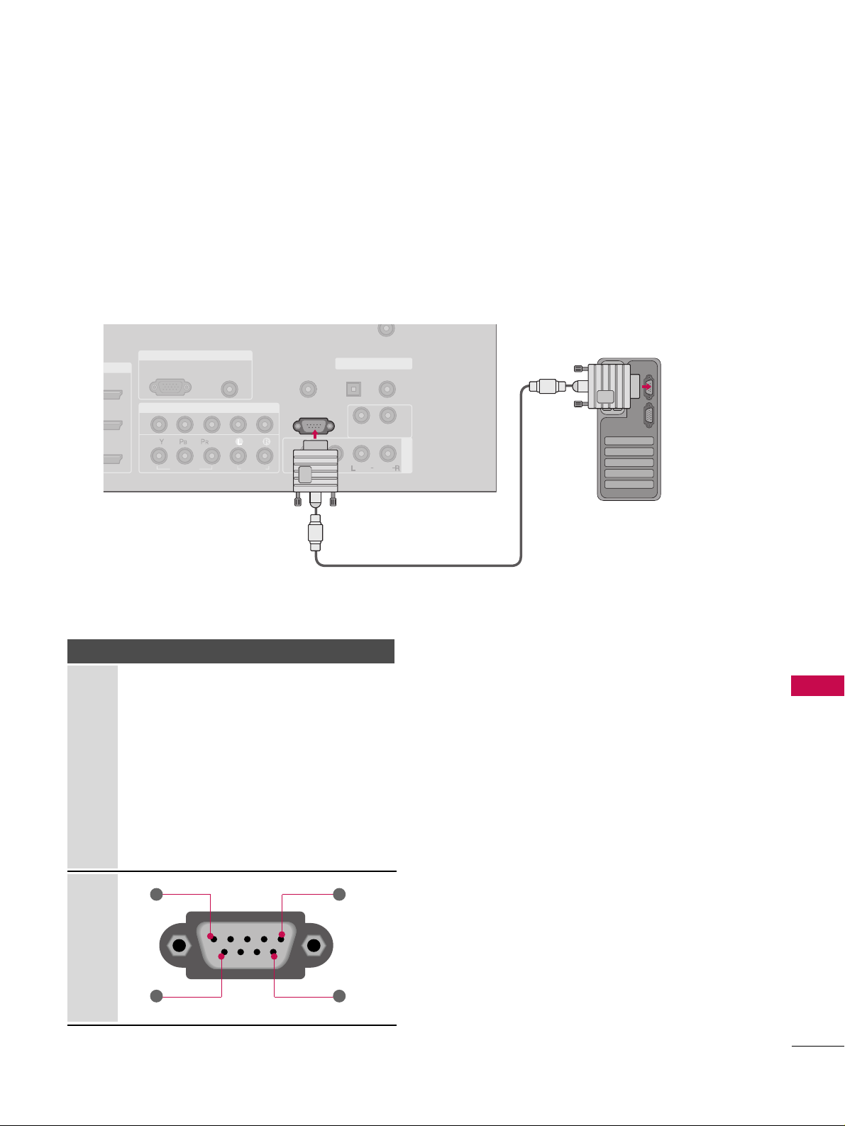
APPENDIX
101
EXTERNAL CONTROL THROUGH RS-232C
RS-232C Setup
The RS-232C port allows you connect the RS-232C input jack to an external control device (such as a computer
or an A/V control system) to control the TV’s functions externally.
■
Note: RS-232C on this unit is intended to be used with third party RS-232 control hardware and software.
The instructions below are provided to help with programming software or to test functionality using telenet
software.
RGB IN
COMPONENT IN
AV IN 1
AUDIO
(RGB/DVI)
RGB(PC)
REMOTE
CONTROL IN
ANTENNA/
CABLE IN
1
2
RS-232C IN
(CONTROL & SERVICE)
VIDEO
AUDIO
AUDIO OUT
OPTICAL COAXIAL
DIGITAL AUDIO OUT
VIDEO
MONO
( )
AUDIO
S-VIDEO
Type of Connector; D-Sub 9-Pin Male
No. Pin Name
1 No connection
2 RXD (Receive data
)
3 TXD (Transmit data
)
4 DTR (DTE side ready
)
5 GND
6 DSR (DCE side ready
)
7 RTS (Ready to send
)
8 CTS (Clear to send
)
9 No Connection
1
6
5
9
PC
Page 82

APPENDIX
102
RS-232C Configurations
APPENDIX
Press the
MMEENNUU
button and then useDDor EEbutton
to select the
OOPPTTIIOONN
menu.
Press the
GG
button and then useDDor EEbutton to
select
SSeett IIDD
.
Press the
GG
button and then useDDor EEbutton to
adjust
SSeett IIDD
to choose the desired TV ID number.
The adjustment range of Set ID is 1~ 99.
Press
EEXXIITT
button to return to TV viewing or press
MMEENNUU
button to return to the previous menu.
Use this function to specify a TV ID number.
Refer to ‘Real Data Mapping1’.
GG
pp..110044
.
Either cable below can be used.
Set ID
TV INPUT
STB
BRIG
HT +
BRI
G
H
T
-
T
I
M
E
R
R
A
T
I
O
S
I
M
P
LINK
M
E
N
U
TV INPUT
STB
TV INPUT
STB
TV INPUT
STB
TV INPUT
STB
MEDIA HOST
MEDIA HOST
MEDIA HOST
MEDIA HOST
MEDIA HOST
Communication Parameters
■
Baud rate : 9600 bps (UART
)
■
Data length : 8 bits
■
Parity : None
■
Stop bit : 1 bit
■
Communication code : ASCII code
■
Use a crossed (reverse) cable.
2
1
3
4
PC TV
RXD 2 3 TXD
TXD 3 2 RXD
GND 5 5 GND
DTR 4 6 DSR
DSR 6 4 DTR
RTS 7 8 CTS
CTS 8 7 RTS
D-Sub 9 D-Sub 9
PC TV
RXD 2 3 TXD
TXD 3 2 RXD
GND 5 5 GND
DTR 4 6 DTR
DSR 6 4 DSR
RTS 7 7 RTS
CTS 8 8 CTS
D-Sub 9 D-Sub 9
7-Wire Configuration
(
Serial female-female NULL modem cable
)
3-Wire Configurations
(
Not standard
)
NOTE
!
GG
This product has command echo back in the RS-232C Command.
Language : English
Input Label
SimpLink : Off
Key Lock : Off
Caption : Off
ISM Method : Orbiter
Low Power : Off
Front Display : Bright
Set ID : 1
Language
Input label
SimpLink
Key Lock
Caption
ISM Method
Low Power
Front Display
Set ID
G
1
1
32
Page 83

APPENDIX
103
Command Reference List
CCOOMMMM AANNDD 11 CCOOMM MMAA NN DD22
23. Channel Tuning
24. Channel Add/Del
25. Key
26. Input Select
27. Back Light
DATA
(Hexadecimal)
CCOOMMMM AANNDD 11 CCOOMM MMAA NN DD22
DATA
(Hexadecimal)
CCOO MMMMAANN DD 11 CCOOMMMMAANNDD22
DATA0
(Hexadecimal)
DATA1
(Hexadecimal)
DATA2
(Hexadecimal)
DATA3
(Hexadecimal)
DATA4
(Hexadecimal)
DATA5
(Hexadecimal)
physical major major low minor high minor low attribute
program high program low
ma
mb0 ~ 1
mc (
GG
p.107)
xb(
GG
p.107)
m g 0~64
01. Power k a 0 ~ 1
02. Input Select k b 0 ~ 9
03. Aspect Ratio k c (
GG
p.104)
04. Screen Mute k d 0 ~ 1
05. Volume Mute k e 0 ~ 1
06. Volume Control k f 0 ~ 64
07. Contrast k g 0 ~ 64
08. Brightness k h 0 ~ 64
09. Color k i 0 ~ 64
10. Tint k j 0 ~ 64
11. Sharpness k k 0 ~ 64
12. OSD Select k l 0 ~ 1
0 ~ 1
Plasma TV Model Only
Transmission / Receiving Protocol
TTrr aannss mmii ssssiioonn
[Command 1] : First command to control the set.
(j, k, m or x)
[Command 2] : Second command to control the set.
[Set ID] : You can adjust the set ID to choose desired TV ID
number in Setup menu. Adjustment range is 1
~ 99.
When selecting Set ID ‘0’, every connected the TV is
controlled. Set ID is indicated as decimal (1
~ 99
)
on
menu and as Hexa decimal (0x0~ 0x63)on transmission
/receiving protocol.
[DATA] : To transmit command data.
Transmit ‘FF’ data to read status of command.
* In this model, TV will not send the status during the standby mode.
[Cr] : Carriage Return
ASCII code ‘0x0D’
[ ] : ASCII code ‘space (0x20)’
OOKK AAcckk nnoowwllee ddgg eemmeenntt
The TV transmits ACK (acknowledgement) based on this format when receiving normal data. At this time, if the data is
data read mode, it indicates present status data. If the data is
data write mode, it returns the data of the PC computer.
* In this model, TV will not send the status during the standby mode.
* Data Format
[Command 2] : Use as command.
[Set ID] : Use the small character, if set ID is 10, it will send the ‘0’, ‘a’.
[DATA] : Use the small character, if data is 0 x ab, it will send the ‘a’, ‘b’.
[OK] : Use the large character.
* In this model, TV will send the echo, CR, LF with acknowl-
edgement message.
* When it send the power on acknowledgement message, it will
be like below.
ex) ka 01 01 (CR) (LF) a 01 OK 01 x (CR) (LF)
EErrrr oorr AAcc kk nnoo wwllee ddgg eemmee nntt
The TV transmits ACK (acknowledgement) based on this format when receiving abnormal data from non-viable functions
or communication errors.
Data1: Illegal Code
Data2: Not supported function
Data3: Wait more time
* In this model, TV will not send the status during the standby mode.
* Data Format
[Command 2] : Use as command.
[Set ID] : Use the small character, if set ID is 10, it will send the ‘0’, ‘a’.
[DATA] : Use the small character, if data is 0 x ab, it will send the ‘a’, ‘b’.
[NG] : Use the large character
* In this model, TV will send the echo, CR, LF with acknowl-
edgement message.
* When it send the power on acknowledgement message, it will
be like below.
ex) ka 01 01 (CR) (LF) a 01 NG 01 x (CR) (LF)
[[ CC oomm mmaa nn dd11 ]][[CCoommmmaanndd22]] [[ ]][[SSee tt IIDD]][[ ]][[DDaattaa]][[CCrr]]
[[ CC oomm mmaa nn dd22 ]][[ ]][[SSeett IIDD]] [[ ]] [[OOKK ]][[DDaattaa]][[xx]]
[[ CC oomm mmaa nn dd22 ]][[ ]][[SSeett IIDD]] [[ ]] [[NN GG]][[ DDaatt aa]][[ xx]]
13. Remote Control
Lock Mode
14. Treble k r 0 ~ 64
15. Bass k s 0 ~ 64
16. Balance k t 0 ~ 64
17.
Color Temperature
k u 0 ~ 3
18. Red Adjustment k v 0 ~ C8
19. Green Adjustment k w 0 ~ C8
20. Blue Adjustment k $ 0 ~ C8
21. ISM Method j p (
GG
p.106)
22. Lo w Power j q 0 ~ 1
k m
Page 84

APPENDIX
104
APPENDIX
00 11.. PPooww eerr (( CC oomm mmaa nn dd 22::aa))
To control Power On/Off of the TV.
Transmission [k][a][ ][Set ID][ ][Data][Cr]
Data 0: Power Off Data 1: Power On
Acknowledgement [a][ ][Set ID][ ][OK/NG][Data][x]
* In a like manner, if other functions transmit ‘FF’ data
based on this format, Acknowledgement data feedback
presents status about each function.
* Note: In this model, TV will send the Acknowledge
after power on processing completion.
There might be a time delay between command and
acknowledge.
0022.. II nnppuutt SSeell eecctt ((CCoommmmaanndd22::bb)) ((MMaaii nn PPiiccttuurree II nnpp uutt ))
To select input source for the TV.
Transmission [k][b][ ][Set ID][ ][Data][Cr]
Data 0: DTV Data 1: Analog
Data 2: AV1 Data 3: AV2
Data 4: Component 1 Data 5: Component 2
Data 6: RGB-PC Data 7: HDMI1
Data 8: HDMI2 Data 9: HDMI3
Acknowledgement [b][ ][Set ID][ ][OK/NG][Data][x]
00 33.. AA ssppeecctt RRaa ttiioo ((CCoommmm aann dd22 ::cc))
To adjust the screen format.
You can also adjust the screen format using the RATIO
button on remote control or in the Picture menu.
Transmission [k][c][ ][Set ID][ ][Data][Cr]
Data 1: 4:3 4: Zoom 1
2: 16:9 5: Zoom 2
6: Set by program
Reserved
Acknowledgement [c][ ][Set ID][ ][OK/NG][Data][x]
00 44.. SSccrr eeeenn MM uutt ee (( CC oomm mmaa nn dd 22::dd))
To select screen mute on/off.
Transmission [k][d][ ][Set ID][ ][Data][Cr]
Data 0: Screen mute off (Picture on)
Data 1: Screen mute on (Picture off)
Acknowledgement [d][ ][Set ID][ ][OK/NG][Data][x]
00 55.. VV oo lluumm ee MMuu ttee ((CCoommmm aann dd22 ::ee))
To control volume mute on/off.
You can also adjust mute using the MUTE button on
remote control.
Transmission [k][e][ ][Set ID][ ][Data][Cr]
Data 0 : Volume mute on (Volume off)
Data 1 : Volume mute off (Volume on)
Acknowledgement [e][ ][Set ID][ ][OK/NG][Data][x]
00 66.. VV oo lluumm ee CCoonnttrrooll ((CCoomm mmaa nn dd 22::ff))
To adjust volume.
You can also adjust volume with the volume buttons on
remote control.
Transmission [k][f][ ][Set ID][ ][Data][Cr]
Data Min : 0 ~ Max : 64
Refer to ‘Real data mapping 1’ as shown below.
Acknowledgement [f][ ][Set ID][ ][OK/NG][Data][x]
00 77.. CCoonntt rraa sstt ((CC oomm mmaa nn dd 22::gg))
To adjust screen contrast.
You can also adjust contrast in the Picture menu.
Transmission [k][g][ ][Set ID][ ][Data][Cr]
Data Min : 0 ~ Max : 64
*Refer to ‘Real data mapping 1’ as shown below.
Acknowledgement [g][ ][Set ID][ ][OK/NG][Data][x]
00 88.. BBrrii gghhttnnee ssss (( CCoomm mmaa nn dd22::hh))
To adjust screen brightness.
You can also adjust brightness in the Picture menu.
Transmission [k][h][ ][Set ID][ ][Data][Cr]
Data Min : 0 ~ Max : 64(*transmit by Hexadecimal code)
*Refer to ‘Real data mapping 1’ as shown below.
Acknowledgement [h][ ][Set ID][ ][OK/NG][Data][x]
*Real data mapping 1
0 : Step 0
A : Step 10 (SET ID 10)
F : Step 15 (SET ID 15)
10 : Step 16 (SET ID 16)
63 : Step 99 (SET ID 99)
64 : Step 100
Page 85

APPENDIX
105
00 99.. CCoolloorr (( CC oo mmmmaa nndd22::ii))
To adjust the screen color.
You can also adjust color in the Picture menu.
Transmission [k][i][ ][Set ID][ ][Data][Cr]
Data Min : 0 ~ Max : 64
*Refer to ‘Real data mapping 1’. See page 104.
Acknowledgement [i][ ][Set ID][ ][OK/NG][Data][x]
11 00.. TT iinn tt (( CC oo mmmmaa nndd22::jj))
To adjust the screen tint.
You can also adjust tint in the Picture menu.
Transmission [k][j][ ][Set ID][ ][Data][Cr]
Data Red: 0 ~ Green: 64
*Refer to ‘Real data mapping 1’. See page 104.
Acknowledgement [ j ][ ][Set ID][ ][OK/NG][Data][x]
11 11.. SShhaarrppnnee ssss (( CC oo mmmmaa nndd22::kk))
To adjust the screen sharpness.
You can also adjust sharpness in the Picture menu.
Transmission [k][k][ ][Set ID][ ][Data][Cr]
Data Min: 0 ~ Max: 64
*Refer to ‘Real data mapping 1’. See page 104.
Acknowledgement [k][ ][Set ID][ ][OK/NG][Data][x]
11 22.. OO SS DD SS eell eecctt ((CCoommmm aann dd22::ll ))
To select OSD (On Screen Display) on/off.
Transmission [k][l][ ][Set ID][ ][Data][Cr]
Data 0: OSD off Data 1: OSD on
Acknowledgement [l][ ][Set ID][ ][OK/NG][Data][x]
11 33.. RReemm oottee CC oonn ttrr ooll LLoocckk MMooddee (( CC oo mmmmaa nn dd 22::mm ))
To lock the remote control and the front panel controls
on the set.
Transmission [k][m][ ][Set ID][ ][Data][Cr]
Data 0: Lock off Data 1: Lock on
Acknowledgement [m][ ][Set ID][ ][OK/NG][Data][x]
If you’re not using the remote control and front panel
controls on the TV, use this mode. When main power is
on/off, remote control lock is released.
11 44.. TT rree bbllee (( CCoomm mmaa nn dd22::rr))
To adjust treble.
You can also adjust treble in the Audio menu.
Transmission [k][r][ ][Set ID][ ][Data][Cr]
Data Min: 0 ~ Max: 64 (*transmit by Hexadecimal code)
*Refer to ‘Real data mapping 1’. See page 104.
Acknowledgement [r][ ][Set ID][ ][OK/NG][Data][x]
11 55.. BB aass ss (( CC oomm mmaa nn dd 22::ss ))
To adjust bass.
You can also adjust bass in the Audio menu.
Transmission [k][s][ ][Set ID][ ][Data][Cr]
Data Min: 0 ~ Max: 64(*transmit by Hexadecimal code)
*Refer to ‘Real data mapping 1’. See page 104.
Acknowledgement [s][ ][Set ID][ ][OK/NG][Data][x]
11 66.. BBaallaa nncc ee (( CC oomm mmaa nn dd 22::tt))
To adjust balance.
You can also adjust balance in the Audio menu.
Transmission [k][t][ ][Set ID][ ][Data][Cr]
Data Min: 0 ~ Max: 64(*transmit by Hexadecimal code)
*Refer to ‘Real data mapping 1’. See page 104.
Acknowledgement [t][ ][Set ID][ ][OK/NG][Data][x]
11 77.. CCoolloorr TTeemm pp eerraattuurree ((CCoommmm aanndd22 ::uu))
To adjust color temperature.
You can also adjust color temperature in the Picture menu.
Transmission [k][u][ ][Set ID][ ][Data][Cr]
Data 0: Medium 1: Cool 2: Warm 3: User
Acknowledgement [u][ ][Set ID][ ][OK/NG][Data][x]
11 88.. RReedd AA ddjjuuss tt mmeenntt (( CC oomm mmaa nn dd ::vv))
To adjust red in color temperature
Transmission [k][v][ ][Set ID][ ][Data][Cr]
Data Min:0 ~ Max:C8
*Refer to ‘Real data mapping 2’ as shown below.
Acknowledgement [v][ ][Set ID][ ][OK/NG][Data][x]
11 99.. GG rr eeee nn AAddjjuussttmm eenntt (( CC oomm mmaa nn dd ::ww))
To adjust green in color temperature.
Transmission [k][w][ ][Set ID][ ][Data][Cr]
Max: C8
*Refer to ‘Real data mapping 2’ as shown below.
Acknowledgement [w][ ][Set ID][ ][OK/NG][Data][x]
*Real data mapping 2
0 : -20
5 : -19
A : -18
5F: -1
64: 0
69: +1
C3 : +19
C8 : +20
Page 86

APPENDIX
106
APPENDIX
22 00.. BBlluu ee AA ddjjuuss tt mmeenntt (( CC oomm mmaa nn dd ::$$ ))
To adjust blue in color temperature.
Transmission [k][$][ ][Set ID][ ][Data][Cr]
Data Min:0 ~ Max:C8
*Refer to ‘Real data mapping 2’. See page 105.
Acknowledgement [$][ ][Set ID][ ][OK/NG][Data][x]]
22 11.. II SS MM MMee tt hhoodd (( CCoomm mmaa nn dd22::pp))
(Only Plasma TV model)
To avoid having a fixed image remain on screen.
Transmission [ j ][p][ ][Set ID][ ][Data][Cr]
Data 1: Inversion 2: Orbiter
4: White Wash 8: Normal
Acknowledgement [p][ ][Set ID][ ][OK/NG][Data][x]
22 22.. LLoo ww PP ooww eerr (( CC oo mmmmaa nndd 22::qq))
(Only Plasma TV model)
To control the low power function on/off.
Transmission [ j ][q][ ][Set ID][ ][Data][Cr]
Data 0: low power off
1: low power on
Acknowledgement [q][ ][Set ID][ ][OK/NG][Data][x]
22 33.. CChhaa nnnnee ll TT uunnii nngg ((CC oomm mmaa nn dd:: mm aa))
To tune channel to following physical/major/minor number.
Transmission [m][a][ ][Set ID][ ][Data0][ ][Data1]
[ ][Data2][ ][Data3][ ][Data4][ ][Data5][Cr]
Digital channels have a Physical, Major, and Minor channel
number. The Physical number is the actual digital channel
number, the Major is the number that the channel should
be mapped to, and the Minor is the sub-channel. Since
the ATSC tuner automatically maps the channel to the
Major number, the Physical number is not required when
sending a command.
Data 0: Physical Channel Number
NTSC air: 02~45, NTSC cable: 01, 0E~7D
ATSC air: 01~45, ATSC cable: 01~87
Data1 & 2: Major Channel Number
Data1: High byte Data2: Low byte
Two bytes are available for the Major and Minor, normally only the second byte is used.
Data3 & 4: Minor Channel Number
Not needed for NTSC.
Page 87

APPENDIX
107
Data5:
The table above lists the binary code which must be
converted to Hexadecimal before sending. For example:
The binary code to tune the sub source to an NTSC
cable channel is “1000 0001”, which translates to “81”
in Hex.
* 7th bit : For which source do you want to change the
channel.
* 6th bit: Use a two part or one part channel. Most cases
just use 0 since it’s ignored when using NTSC.
* 5th bit: Use 0 with NTSC since it can only use the phys-
ical channel number. Normally use 1 for ATSC since most
times it doesn’t matter what the physical number is.
* 4th bit: Set to 0.
* 3-0 bits: Choose signal type.
* Tune Command Examples:
1. Tune to the analog (NTSC) cable channel 35.
Data 0 = Physical of 35 = 23
Data 1 & 2 = No Major = 00 00
Data 3 & 4 = No Minor = 00 00
Data 5 = 0000 0001 in binary = 01
Total = ma 00 23 00 00 00 00 01
2. Tune to the digital (ATSC) local channel 30-3.
Data 0 = Don’t know Physical = 00
Data 1 & 2 = Major is 30 = 00 1E
Data 3 & 4 = Minor is 3 = 00 03
Data 5 = 0010 0010 in binary = 22
Total = ma 00 00 00 1E 00 03 22
Acknowledgement[a][ ][Set ID][ ][OK][Data0][Data1]
[Data2][Data3][Data4][x][a][ ][Set ID]
[ ][NG][Data0][x]
22 44.. CChhaa nnnnee ll AA dd dd//DDeell ((CCoommmm aann dd:: mm bb))
To add and delete the channels
Transmission [m][b][ ][Set ID][ ][Data][Cr]
Data 0: Channel Delete Data 1: Channel Add
Acknowledgement [b][ ][Set ID][ ][OK/NG][Data][x]
22 55.. KK eeyy (( CC oo mmmmaa nndd:: mm cc))
To send IR remote key code.
Transmission [m][c][ ][Set ID][ ][Data][Cr]s
Data Key code: Refer to page 100.
Acknowledgement [c][ ][Set ID][ ][OK/NG][Data][x]
22 66.. II nnppuutt SSeell eecctt ((CCoommmm aann dd:: xx bb))
To select input source for TV.
Transmission [x][b][ ][Set ID][ ][Data][Cr]
Data 00 : DTV (Antenna) Data 01 : DTV (Cable)
Data 10 : Analog (Antenna) Data 11 : Analog (Cable)
Data 20 : AV1 Data 21 : AV2
Data 40 : Component 1 Data 41 : Component 2
Data 60 : RGB-PC Data 90 : HDMI1
Data 91 : HDMI2 Data 92 : HDMI3
Acknowledgement [b][ ][Set ID][ ][OK/NG][Data][x]
22 77.. BBaacckk LLii gg hhtt ((CCoommmm aanndd:: mm gg))
To adjust screen back light.
Transmission [m][g][ ][Set ID][ ][Data][Cr]
Data Min:0 ~ Max:64
Acknowledgement [g][ ][Set ID][ ][OK/NG][Data][x]
Step
NTSC Air
NTSC Cable
ATSC Air
ATSC Cable_std
ATSC Cable_hrc
ATSC Cable_irc
ATSC cable_auto
Reserved
...
Reserved
1
0
0
1
1
0
0
1
1
x
1
2
0
0
0
0
1
1
1
1
x
1
3
0
0
0
0
0
0
0
0
x
1
4
x
x
x
x
x
x
x
x
x
x
Reserved
5
01Use
No Use
Using Physical
Channel
6
01Tw o
One
Two/One
Part Channel
7
01Main
Sub
Main/Sub
Picture
0
0
1
0
1
0
1
0
1
x
1
Page 88

 Loading...