

Page 1
How to acquire bright image with X-Ray shot. This procedure is also applied for pediatric patient.
X-ray generator connection is explained in this manual page from 46 to 48.
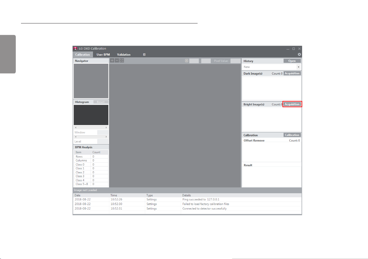
1 Click the “Acquisition” Button next to Bright Image(s) text.
ENGLISH
46
Page 2
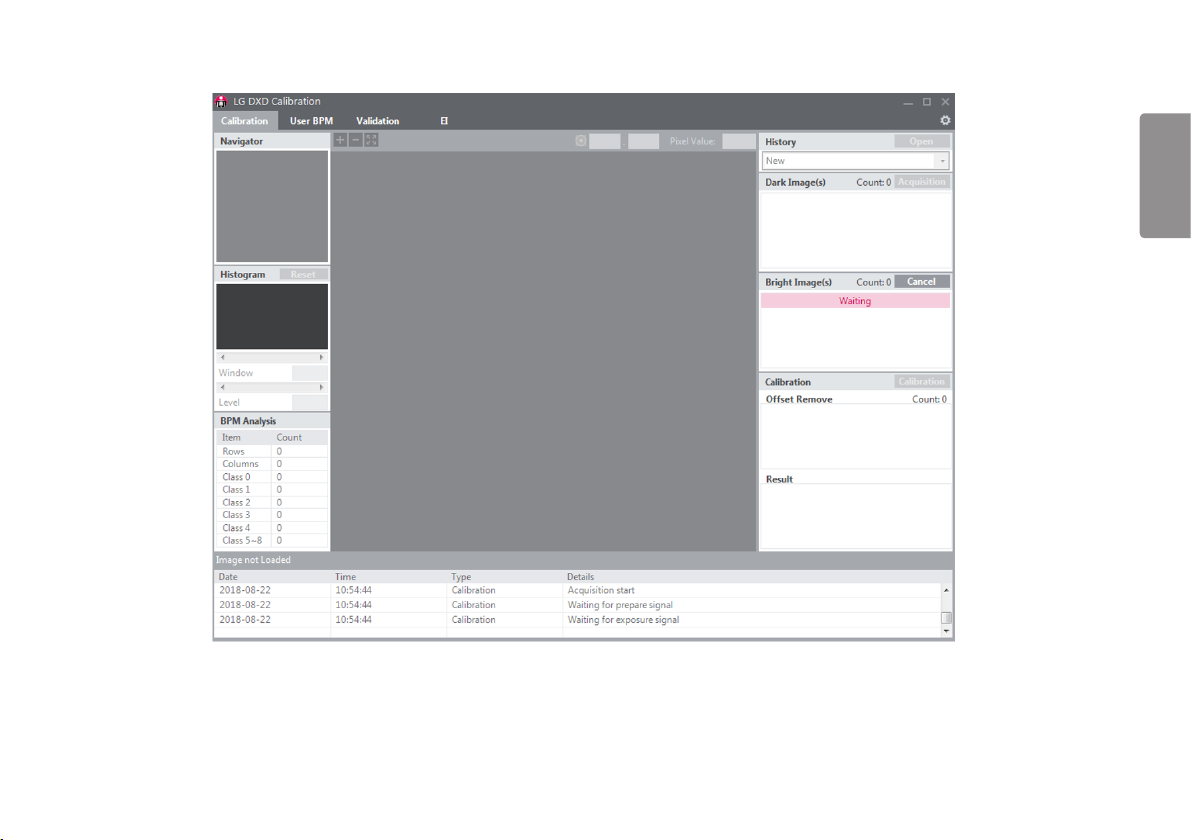
2 Implement “X-ray Shot”. Calibration SW will wait X-Ray acknowledge signal from DXD and it will display waiting sign.
ENGLISH
47
Page 3

3 Acquired bright image is displayed in list view, please check its name and median value. Actual file is saved “Image” folder in the workspace.
ENGLISH
NOTE
• These acquisition steps are all same to User BPM, Validation and EI image acquisition.
• Calibration SW support Window level adjustment, but does not support other image post-processing function.
• The process of obtaining the image for pediatric patients is same with other patients.
48
Page 4

CALIBRATION SOFTWARE
To ensure that optimal image quality is obtained from the detector, the detector must be calibrated. The Calibration Software generates and verifies the values necessary for calibration.
NOTE
• To ensure optimal image quality, you should calibrate every month for the first three months after the purchase and half-yearly calibration thereafter.
• It is recommended that you leave the detector on for 15 minutes before calibrating.
• The default value of Calibration Software could be changed depends on Detector.
Calibration Software
The features of the Calibration Software include Settings, Calibration, User BPM, Validation and Exposure Index.
ENGLISH
49
Page 5
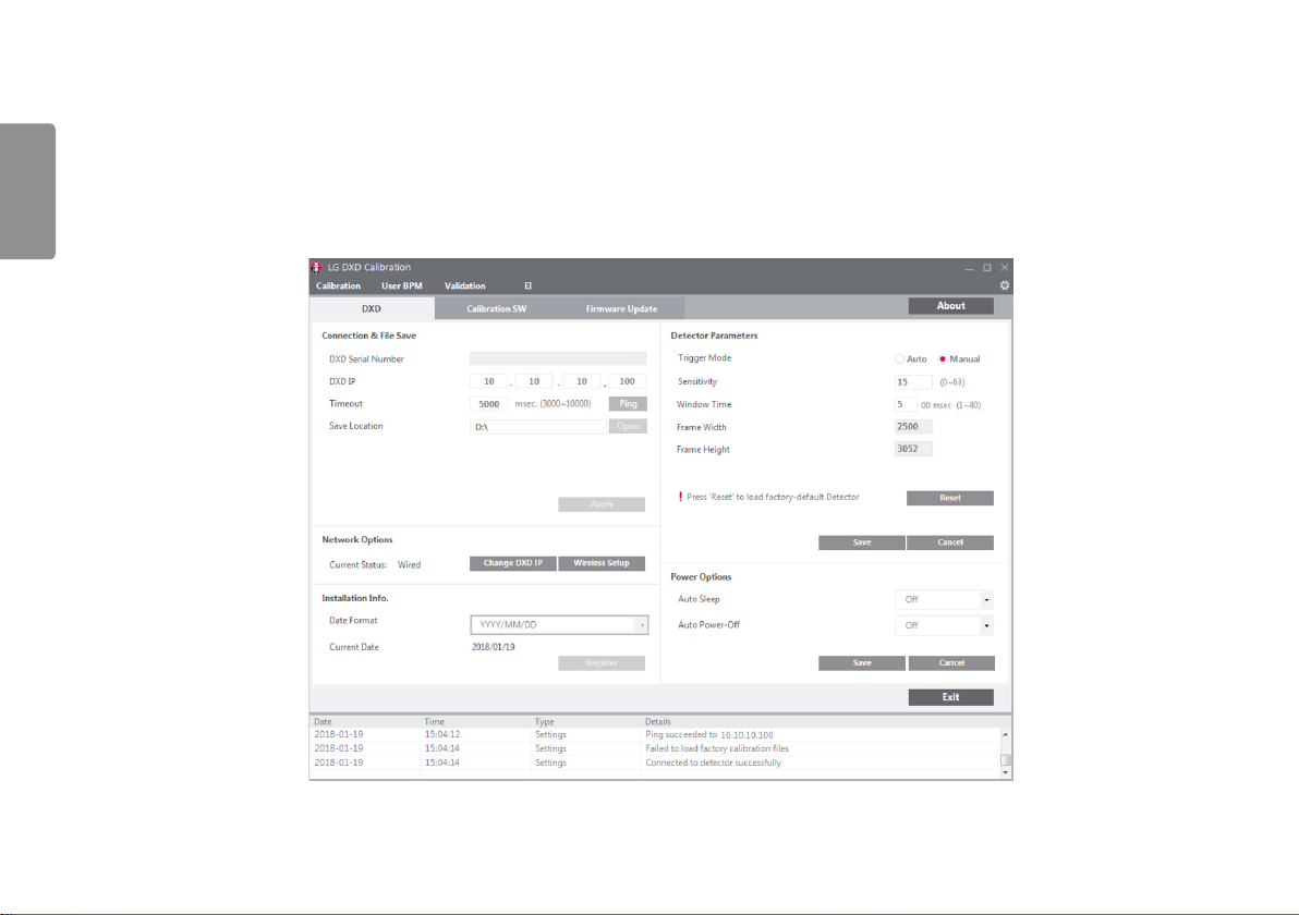
Settings
Settings include DXD settings, Calibration SW settings and Firmware Update.
• DXD: Configures the settings required to obtain calibration images and detector settings.
ENGLISH
50
Page 6
• Calibration SW: Configures the settings required for to calibrate software algorithms.
ENGLISH
51
Page 7

• Firmware Update: Checks the firmware version of the detector or performs the firmware update.
ENGLISH
<Settings Screen: Firmware Update>
52
Page 8
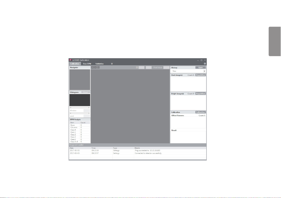
Calibration
Calibration involves the following procedures.
• Dark Image and Bright Image are obtained from the detector.
- Dark Image: An image obtained without generating X-rays.
- Bright Image: An image obtained by generating X-rays without a phantom or any other object on the detector.
• Generate Avg dark, Offset, and Gain: Used for Corrected Image calculations.
- Corrected Image: An image generated by applying calibration results to a raw image.
• Generate Bad Pixel Map: Bad pixel values are calibrated using surrounding pixel values.
ENGLISH
<Calibration Screen>
53
Page 9

User BPM
This is used to assign additional bad pixels in BPM.raw after calibrating.
ENGLISH
<User BPM Screen>
54
Page 10

Validation
This is used to validate the final image by applying calibration results to the image.
ENGLISH
<Validation Screen>
55
Page 11

EI(Exposure Index)
This calculates and saves median output value per input dose as a linear expression and a table.
ENGLISH
<EI Screen>
56
Page 12
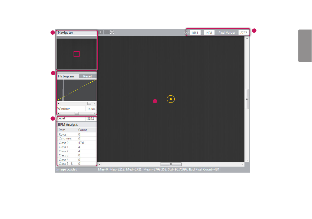
Image Functions
2
5
4
ENGLISH
3
1
57
Page 13

1
Image Viewer
• The Calibration, User BPM, Validation, and EI menus include an image viewer that lets you view the
acquired images.
• An image is loaded and displayed when it is acquired or clicked.
ENGLISH
• Information about the image is displayed in the following sections.
- Image Loaded: Indicates whether an image is loaded in the image area.
* When an image is loaded: Image Loaded.
* When no image is loaded: Image not Loaded.
- Min: Minimum pixel value within the image area.
- Max: Maximum pixel value within the image area.
- Med: Median value of the image.
- Mean: Mean value of the image.
- Std: Standard deviation value of the image.
- Bad Pixel Count: Bad pixel count in the image area.
- 16B = N, 8B = M: Representation of the pixel value at (x,y) in bits.
- %: Percentage of the image shown in the image area compared to the entire image size.
- (W x H): Size of the entire image.
2
Navigator
• The Navigator shows the entire area of the acquired image and indicates the zoomed in/out area.
• The red rectangle in the Navigator indicates the area shown in the Image Viewer.
• Clicking a position in the Navigator moves the red rectangle to the position and displays the area in the Image
Viewer.
3
Histogram
• Histogram of the acquired image is shown here.
• Window / Level can be adjusted for better image distinction.
• Use the <> buttons or the scroll bars below the Histogram graph to adjust Window / Level.
• Click the Reset button to restore the default values.
4
Reference Point
• When you click a position inside the Image Viewer, a reference point is specified, and the coordinates and pixel
value of the reference point are shown at the top. You can also move the reference point by entering the x and
y values manually.
- Since reference point coordinates are numbers, only numeric values can be entered.
5
Bad Pixel Map Analysis
• Displays the results of bad line and bad pixel class analysis based on the Bad Pixel Map after calibration.
58
Page 14

Log
This shows the necessary information about the application execution process that is helpful to the user.
It consists of the Date, Time, Type and Details, which are saved as a log file.
ENGLISH
59
Page 15
USAGE
ENGLISH
Launching the Program
• Double-click the executable file installed on your PC to launch the calibration software.
• If launching for the first time, the Settings screen appears.
60
Page 16
Checking IP Address and Ping Test
• A default IP address is entered for the detector.
• If you change the IP address of the detector, enter the new detector IP address in the detector IP field of the calibration tool.
• For instructions on changing the detector IP address, see "Detector and PC (Wired mode)".
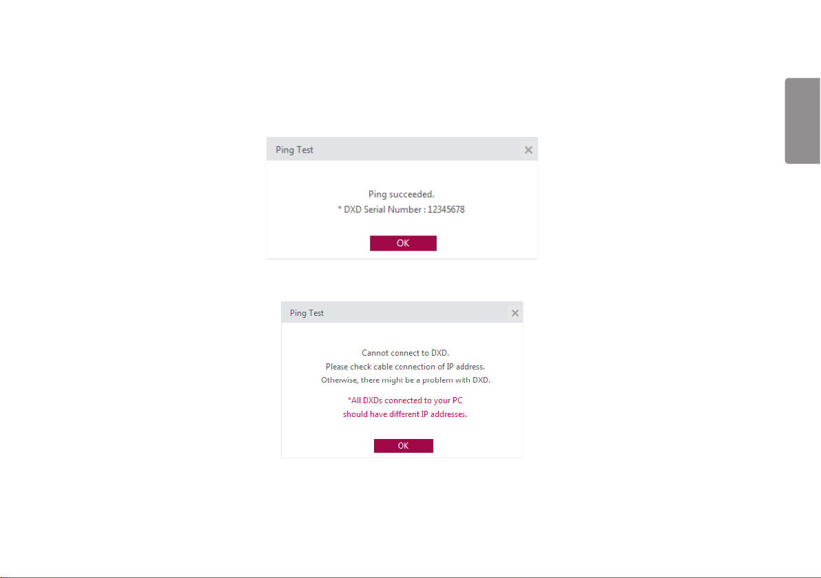
• After entering the IP address, set a timeout value and click the Ping button to perform a Ping Test. A pop-up message appears if the Ping Test is successful.
• The following pop-up window appears if the Ping Test is unsuccessful. If the pop-up window appears, check your PC's network settings, the connection between the detector and PC, the detector status, the Control Box status and
the IP address, then perform the Ping Test again.
ENGLISH
61
Page 17

Checking Save Location
While the calibration software is run, the acquired images, logs, result files and factory-default calibration results are saved in the designated location.
You can change the storage path in the Save location.
ENGLISH
Click the Apply button when a folder is created in the specified path.
NOTE
• Default: C:\Users\heuser\Documents\LG DXD Calibration
• heuser: User name
62
Page 18

Apply
After performing the Ping Test and verifying the Save Location, click the Apply button to perform the following procedures.
1 Automatically create the necessary folders in the save location designated in the Checking Save Location stage.
2 Load from the detector and save the factory-default calibration results.
3 Load the detector's settings.
User-specified
folders
Automatic creation of the Serial Number folder
(Created when Apply is complete)
Condition: Created if the same Serial Number folder is not found
in the custom folder
Creation of date/time folder
(Created when the Calibration button is clicked)
Log Shows logfile including connections
Image Bright Images
Factory calibration
(Created when Apply is complete if the folder or files do not
exist or if the files are abnormally small)
ENGLISH
Avgdark.raw
Gain.raw
Offset.raw
BPM.raw
EI results
(A folder is created for the date/time applied at the time of EI.)
History file
Dark Images
User BPM images
Validation images
EI images
Raw images
Avgdark.raw
Gain.raw
Offset.raw
BPM.raw
63
Page 19

4 When Apply is successful, the detector's network status is displayed.
Current Status : Wired Connection.
Wireless Connection (Only for wireless model)
ENGLISH
NOTE
• Other menus remain inaccessible until you perform Apply. (Calibration, User BPM, Validation, EI)
64
Page 20

Checking and Changing Detector Settings
Upon Apply, the current detector settings are loaded on the settings screen below.
ENGLISH
65
Page 21

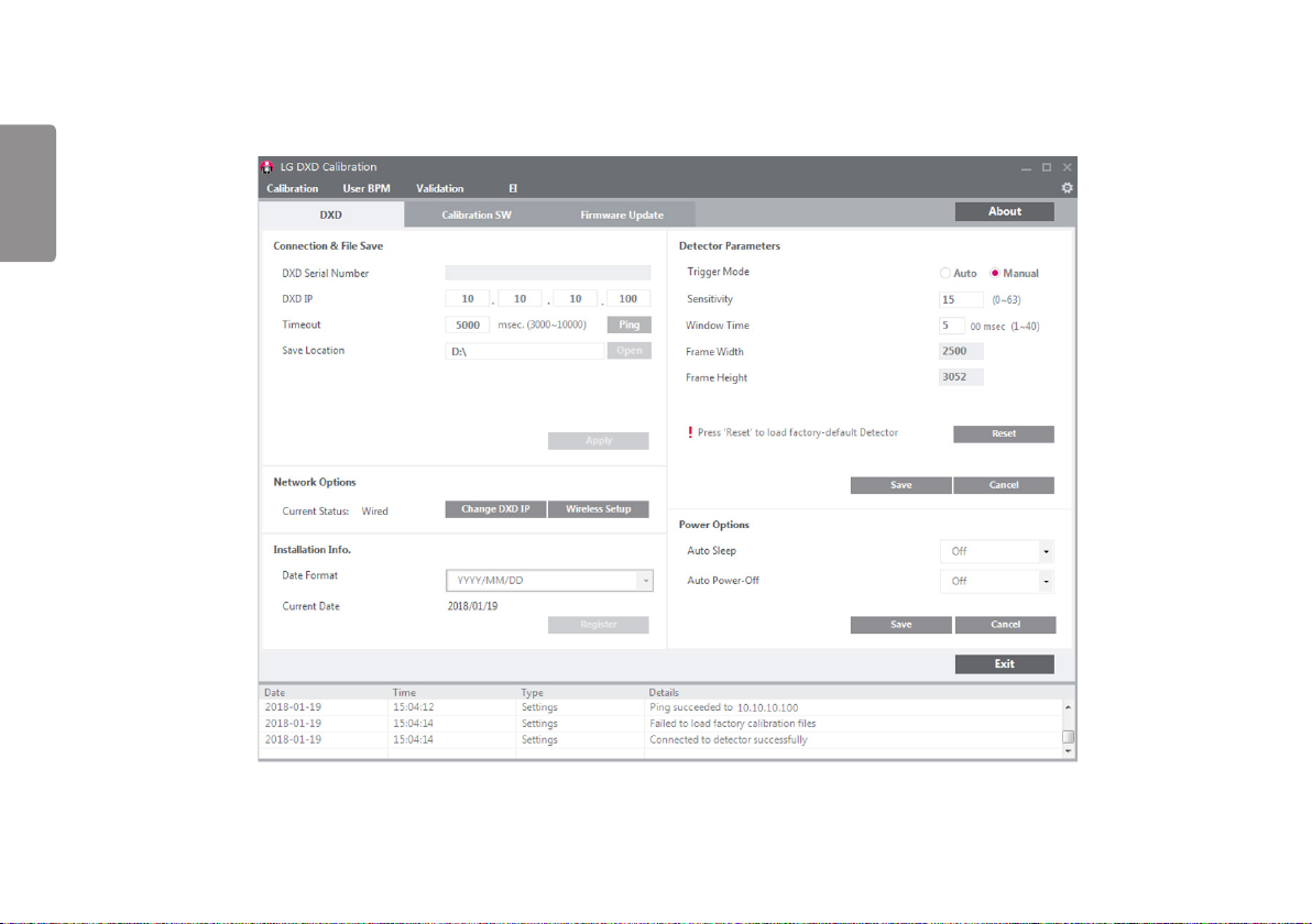
• Detector Parameters are parameters used when obtaining images from the detector.
• Click the Save button to apply the settings entered.
• Descriptions of the data are as follows.
ENGLISH
- Trigger Mode : This sets Trigger Mode.
* Auto : Enables the Auto Exposure Detection feature.
* Manual : Disables the Auto Exposure Detection feature.
- Sensitivity : This is the panel sensitivity.
- Window Time : This sets the time taken to read the values after the x-ray exposure. (An input value of 5 means 500 ms)
- Frame Width / Frame Height : Pixel number of width / height of Detector.
• Descriptions of the buttons are as follows.
- Save : Applies the changes.
- Reset : Loads the factory default settings.
- Cancel : Loads the last saved values.
66
Page 22

Checking and Changing Calibration Software Settings
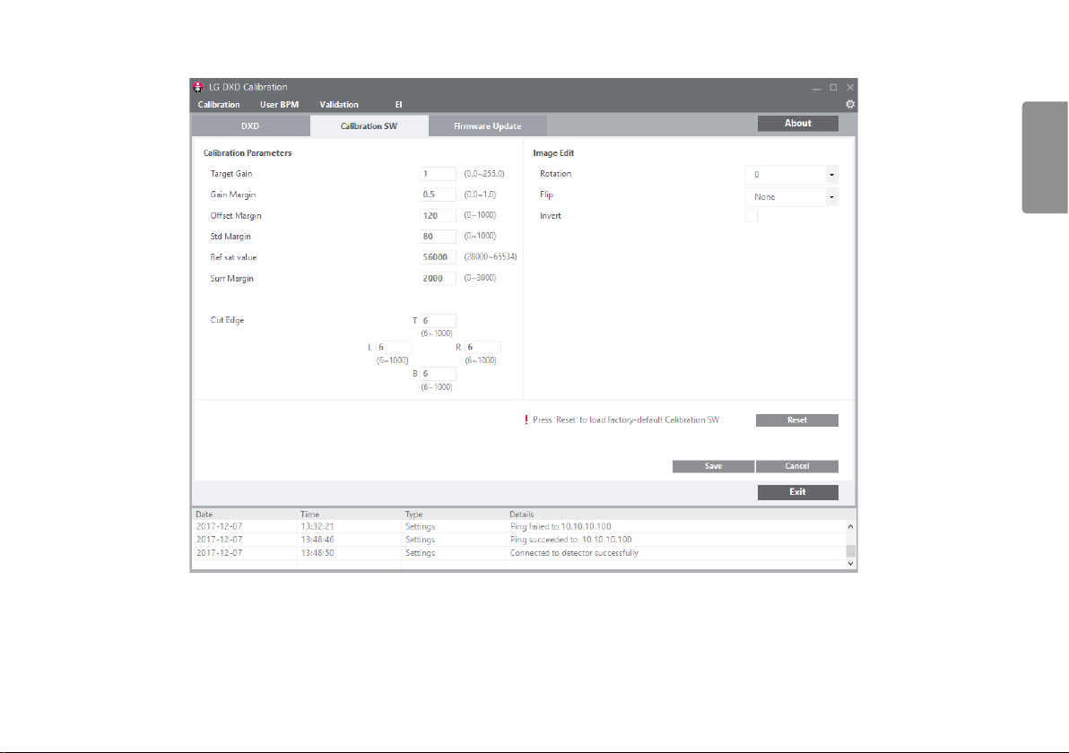
The Calibration Parameters are updated when the Calibration SW tab is clicked.
Calibration Parameters
These settings are used to Calibration Parameters.
•
ENGLISH
67
Page 23

• Descriptions of the data are as follows.
- Target Gain : Amplification level within algorithms.
- Gain Margin : Pixels with values that exceed the Gain Margin are specified as bad pixels.
ENGLISH
- Offset Margin : Pixels with values that exceed the Offset Margin are specified as bad pixels.
- Std Margin : Pixels with values that exceed the Std Margin are specified as bad pixels.
- Ref Sat Value : Maximum lsb value of pixels.
- Surr Margin : In corrected bright images, if the difference between the standard pixel value and
- Cut Edge : This indicates the pixel values to cut off in the top, bottom, left or right directions of the frame.
After acquiring an image in Validation or EI, the border of the image to cut off is indicated as
lines in the Image Viewer.
surrounding pixel value exceeds the Surr Margin, the standard pixel is specified as a bad
pixel.
Image Edit
These are Image Viewer settings of the selected tool.
• Rotation : This sets the rotation angle of the image. (0°, 90°,180°, 270°)
• Flip : Sets how the image shown in the Image Viewer is rotated. (None, Horizontal, Vertical)
• Invert : Inverts the image data shown in the Image Viewer.
• Click the Save button to apply the settings entered.
• Descriptions of the buttons are as follows.
- Save : Applies the changes.
- Reset : Loads the factory default settings.
- Cancel : Loads the last saved values.
- Exit : Return to the previous screen.
NOTE
• The next stage will not be accessible until you perform Apply.
68
Page 24

Calibration
After configuring all settings, click the Calibration tab to open the Calibration menu.
NOTE
• This tab cannot be accessed until the settings have been configured.
1
ENGLISH
5
2
3
4
69
Page 25

1
Open Calibration Menu
- Click the Calibration menu button to open the menu.
2
Get Dark
The menu is used to acquire dark images necessary for performing calibration.
ENGLISH
- When a dark image is acquired, the image count increases and the image file is saved in the Image folder
within the location specified in Settings.
- After acquiring an image, the median value of the image is shown next to the file name.
- After comparing multiple images, you can delete any abnormal images by right-clicking them.
- When deleted, both the list entry and the file are deleted.
3
Get Bright
The menu is used to acquire bright images necessary for performing calibration.
- When a bright image is acquired, the image count increases and the image file is saved in the Image folder
within the location specified in Settings.
- After acquiring an image, the median value of the image is shown next to the file name.
- After comparing multiple images, you can delete any abnormal images by right-clicking them.
- When deleted, both the list entry and the file are deleted.
NOTE
• All the images are deleted when Calibration SW ends. For backup, copy the images and paste them into
another folder.
• Up to 10 images can be saved.
• Dark Image: An image obtained without generating X-rays.
• Bright Image: An image obtained by generating X-rays without a phantom or any other object on the detector.
4
Calibration
This area is used for Calibration.
• For Calibration, following images are required.
- Dark Image : minimum 4 dark images.
- Bright Image : minimum 5, maximun 10 bright image.
- lsb ranage is recommended from 8800 ~ 18000 lsb.
- The recommended lsb level is 8900, 9100, 9200, 9300, 9600, 10000, 11000, 12000, 14000, 16000 lsb.
• Calibration result files are saved in a created new folder based on name of the date and time of the
Calibration.
• The BPM Analysis is updated when the calibration is complete.
70
NOTE
• When Calibration is performed more than five times, the oldest results are automatically replaced with new
results.
• For backup, copy the results folder and paste the results into another folder.
5
History
- You can load previous calibration results. Click the Open button to load the previous Calibration result files.
NOTE
• Selecting any one of the files also loads other associated files. (Select any one of the Avgdark, Offset, Gain or
BPM files, and all the four associated files will be loaded)
• If there is a problem while loading the files, the following error popup window appears. If the popup window
below appears, check the file sizes, path, file names and folder access permissions, and then try again.
Page 26

User BPM
The user can manually edit the Bad Pixel Map created during Calibration in this menu.
NOTE
• You can skip the User BPM stage and proceed to Validation.
ENGLISH
1
2
3
4
71
Page 27

1
Open User BPM Menu
- Click the User BPM menu button to open the menu.
ENGLISH
NOTE
• The pop-up window below will appear if you open this menu without performing Calibration.
2
Check History File
- Check that the History name created during Calibration matches the name shown in the current History window.
- The User BPM procedure is performed by applying the selected History.
72
Page 28

3
Image Acquisition
- User BPM requires image acquisition as it involves a visual inspection of images with applied Calibration
results. When the Acquisition button is clicked and a Bright Image is acquired, the name of the image will
appear in the image list.
4
Pixel View
• Check pixel values in Pixel View.
- Pixel values for the center of the Image Viewer are displayed in the Pixel View window.
- The minimum value, maximum value and pixels estimated as bad pixels are shown as below.
* Minimum value : Indicated as a blue number.
* Maximum value : Indicated as a red number.
* Estimated bad pixels : Indicated with gray background.
- The size of the Pixel View window can be adjusted using the icon. The mouse pointer changes to a
icon when hovering over the border between the Pixel View and Image Viewer.
• Mark additional bad pixels in Pixel View.
- Double-click a pixel in Pixel View to mark it as a bad pixel. Double-click a bad pixel again to unmark it.
- As you mark bad pixels, the values in Bad Pixel Analysis are updated in real time. Also, pixels marked as bad
pixels are replaced with calibrated pixel values.
• Saving Final User BPM.
- The result file is saved when a different menu is opened.
- When you attempt to exit the current menu and open another menu, a popup window appears asking
whether you want to save the data.
- Select Save to add a History entry and save an updated version of the BPM.raw file.
ENGLISH
73
Page 29

Validation
This procedure allows you to perform a visual inspection of the Calibration results after completing Calibration.
ENGLISH
1
2
3
4
74
Page 30

1
Open Validation Menu
- Click the Validation menu button to open the menu.
NOTE
• The pop-up window below will appear if you open this menu without performing calibration.
2
Check History File
- Please confirm whether the name of the History file created during calibration matches the name displayed
in the History window.
3
Image Acquisition (Procedure matches that from the User BPM stage)
- When the Acquisition button is clicked and a bright image is acquired, the name of the image will appear
in the image list.
- Information about the image is displayed below the Image Viewer.
4
Apply/Unapply Calibration Results
- You can apply/unapply calibration results (Dark Average Map, Offset Map, Gain Map, Bad Pixel Map)
to the acquired image.
: Apply
: Unapply
NOTE
• When an image is acquired and loaded for the first time, all results are (Apply) by default.
• If no image has been acquired, the (Apply)/ (Unapply button is disabled.
ENGLISH
75
Page 31

EI (Exposure Index)
ENGLISH
1
2
3
4
5
76
Page 32

1
Open EI Menu
- Click the EI menu button to open the menu.
NOTE
• The pop-up window below will appear if you open this menu without performing calibration.
5
Measure & Save
- When you click the Measure & Save button after acquiring an image and entering a dose value, the popup
notification below appears.
- The results are saved in the save location specified for EI calculation.
(Example: C:\Users\heuser\Documents\LG DXD Calibration\Serial Number\Calibration Results Folder (Time and
Date) heuser: Username)
ENGLISH
2
Check History File
- Please confirm whether the name of the History file created during calibration matches the name displayed
in the History window.
3
Image Acquisition (same as User BPM and Validation)
- When the Acquisition button is clicked and a Bright image is acquired, the name of the image will appear
in the image list.
- Information about the image is displayed below the Image Viewer.
4
Enter Dose Value
- Enter an X-ray dose in the dose input field. (Unit: uGy)
- The EI value is calculated based on the input value.
- Because the dose value is a number, only numeric values can be entered. Non-number values cannot be
entered automatically.
NOTE
• When Measure & Save is repeated, the results file in the folder is updated.
• The following pop-up window appears if the minimum number of images required (three) is not met.
77
Page 33

Exit
When you click the Quit button, the calibration tool quit popup window appears.
In the popup window below, click the Yes button to quit or click the No button to return to the previous screen.
ENGLISH
78
Page 34

About
When you click the About button in Settings, the following popup window appears.
It shows the information about the application.
ENGLISH
79
Page 35

General PopUp
The following are descriptions of the general pop-up windows that may appear when the calibration software is
being used.
ENGLISH
Image Acquisition Cancellation
• When the Acquisition button is clicked for image Acquisition, it will be replaced with a Cancel button while
the image is being acquired.
• Once image acquisition is complete, the button will revert to an Acquisition button.
• During image acquisition, you can cancel the process by clicking the Cancel button.
<Get Dark Image Cancel Button: Available in Calibration>
<Get Bright Image Cancel Button: Available in Calibration>
<Get Image Cancel Button: Available in User BPM, Validation, EI>
• The popup window below appears when the cancellation is complete.
80
Page 36

<Get Image Cancel Complete Popup Window>
Image Acquisition Failure
• The popup window below appears when image acquisition fails. Check the network and Detector status, then
try again.
<Image Acquisition Failure Popup Window>
ENGLISH
81
Page 37

SERVICE MANUAL
ENGLISH
Detector Wired IP Address Setting
1 From the "Usage" section, perform "Launching the Program", "Checking IP Address and Ping Test", "Checking Save Location" and "Apply".
2 Click the Change DXD IP button.
82
Page 38

3 At the popup window, change the setting and click the Apply button.
- When the Apply button is clicked, the system attempts to change the IP address.
4 Check the result and restart the detector.
- The following popup windows appear, depending on the successful and failed.
ENGLISH
<Popup Window for Successful Configuration>
- Once the new IP address is applied, restart the detector so that the new setting takes effect.
- Restart the detector automatically using the program.
- Because the detector is disconnected when restarting, perform the Connection & File Save process again.
83
Page 39

Wireless AP configuration
To have the Detector connect wirelessly to an AP, the AP information must be saved in the Detector in advance.
Once the AP information is transferred and saved in the Detector, the Detector attempts to connect to the AP.
ENGLISH
The saved AP information can be viewed in the Web Monitoring feature.
1 From the "Usage" section, perform "Launching the Program", "Checking IP Address and Ping Test", "Checking Save Location" and "Apply".
2 After checking that wireless settings are enabled on the PC, click the Wireless Setup button.
84
Page 40

- If a pop-up appears, enter your SSID and password, then click Apply.
3 Check results.
- The following popup windows appear, depending on the result.
ENGLISH
NOTE
SSID can be appear garbled or as question marks or boxes and others because of encording or compatibility.
<Popup Window for Successful Configuration>
<Popup Window for Failed Configuration>
85
Page 41

Detector Firmware Update
This menu allows you to check the firmware version of the detector or update the firmware.
From the "Usage" section, perform "Launching the Program", "Checking IP Address and Ping Test", "Checking Save Location" and "Apply".
ENGLISH
1
2
86
3
4
Page 42

1
Select the Firmware Update tab.
2
Check the current firmware version.
- The current firmware version of the detector is shown here when the PC is connected to the detector.
3
Select a firmware file to update.
- Click the Open button to open a file browser window. When you select a file to update, the system validates
the file.
- If the file is correct, the file name appears in the Firmware File section.
- If the file is invalid, the following popup window appears.
<Popup Window for File Loading Failure>
4
Perform the update.
- Select a file, then click the Update button to start the Update process.
- The progress status is shown in the Status field.
CAUTION
• Do not remove the power cable until the update is complete. The update may not be successful if the power is
disconnected during the update process.
5
Check results.When the update is complete, the result is shown in a popup window.
<File Update Successful Popup Window>
<File Update Failed Popup Window>
ENGLISH
<File Updating Popup Window>
87
Page 43

Storage of installation date
The date of the first calibration can be saved in the detector.
1 From the "Usage" section, perform "Launching the Program", "Checking IP Address and Ping Test", "Checking
ENGLISH
Save Location" and "Apply".
2 Select the Settings > DXD tab.
3 Check the installation date and select a date format.
- YYY Y: Year
- MM: Month
- DD: Day
NOTE
• The date is displayed based on the OS information.
5 Select the Yes button in the pop-up window to save the information in the detector. Once the information is
saved, the Register button will be disabled.
4 Click the Register button to open a pop-up window. The installation date can be checked through the Web
Monitoring feature.
CAUTION
• Be careful, as this information is saved only once per detector and cannot be edited later.
88
Page 44

Power Options Setting
This menu allows you to save the Power Options of detector.
1 From the "Usage" section, perform "Launching the Program", "Checking IP Address and Ping Test", "Checking Save Location" and "Apply".
2 Select the Settings > DXD tab.
3 Select the options of Auto Sleep and Auto Power-Off.
4 Click the Save button to save the options on Detector.
NOTE
• Calibration Software only saves the options.
• Detector enters the the Power Mode when there is no communication during the setting times.
• The Detector does not enter the Power Mode while the Calibration Softwere runs(from the Apply to exit) because the Calibration Software checks the Detector‘s status Periodically.
• This feature is only enabled wireless models.
ENGLISH
89
Page 45

Web monitoring
This feature displays the detector's release date, installation date, software version and other internally managed information in a web browser.
ENGLISH
Internal Information
Category Content Description
Product information Software version • Currently installed detector firmware version
Product release date • Product manufacture date
Product installation date • Installation date as registered by the installer
Model number • Product model number
Serial No. • Product serial information
Network Connection status • Network connection mode (wired)
IP • Detector's IP address
SSID • Connected wireless AP SSID
Netmask • Detector Netmask
Gateway • Detector Gateway
Mac • Product MAC address
Battery Status • Battery level, charging status notification, Auto Sleep , Auto Power off
ETC Bright image count • Number of times images were acquired by generating X-Rays
Dark image count • Number of times images were acquired without generating X-Rays
90
Page 46

Web monitoring
1 Establish a wired/wireless connection between the detector and the PC.
- Refer to the "Detector and PC (Wired mode)" section for instructions.
2 Enter the IP address in the address input of the detector PC web browser.
3 The default IP address: 10.10.10.100 enter the page as below appears.
ENGLISH
91
Page 47

MAINTENANCE
ENGLISH
Cleaning
• Make sure to turn the detector off before cleaning.
Inspection
• Check the detector regularly to ensure that it operates stably and properly. If a problem occurs, please contact the manufacture.
• Use the checklist below as a reference for checking the product.
Checklist Inspector Cycle
Is the cable damaged? User Daily
Is the plug or are the connectors loose or damaged? User Daily
Is the detector scratched or cracked on the surface? User Daily
Is the LED power working properly? User Daily
Scheduled calibration Vendor 3 to 6 months
Performance inspection Vendor Yearly
92
Page 48

TROUBLESHOOTING
Problems that occur while using the detector can be solved by using the information on this page. If problems persist, please contact manufacturer.
Problem Action
The product does not turn on. • Check that the power cord is properly connected.
• After disconnecting and reconnecting the power cord, press the power button on the product.
The product was suddenly turned off during
use.
The Control Box Ready/Exposure LED flashes
in orange.
The PC and the detector are not connected. • Check the power supply. If on, check the following:
There is a problem with acquired images. • Check whether the detector surface is soiled.
• Check that the power cable is properly connected.
• Check the power cable connection of the control box.
• Check that the control box is properly connected to the generator or the detector.
• Check that the connection is made as instructed in the manual. Try connecting again.
• Perform the Ping Test in Settings > Connection & Save Location section of Calibration Software to check your connection. You can also check your connection by entering the
IP address in the address bar of the browser window and checking whether the page is properly loaded.
• Check whether the network IP address of your PC is using the same IP address as the detector.
• In some cases, especially Win 8 OS, it might be problem in connection because of firewall rule that blocks all incoming ICMP packets. Please refet to next page, "Solution for firewall
block".
• Images acquired immediately after turning the detector on may be incorrect due to instability of the panel. Open the Calibration menu of the Calibration Software. Acquire some
dark images first or wait a while before proceeding.
• If the images continue to be unstable, perform Calibration, apply the results, then continue.
ENGLISH
93
Page 49

ACCESS PROBLEM TO START PROGRAM
1 Launch program > Ping > Apply, check the access problem popup as below.
ENGLISH
2 Click mouse right button on Calibration SW icon > Property. 3 Enter compatibility tab and check “Run this program as an administrator.”
94
Page 50

SOLUTION FOR FIREWALL BLOCK
If Calibration Software connection doesn’t work for firewall in Windows 8, refer to instructions as below.
1 Enter into control panel and click on the System and Security link.
ENGLISH
95
Page 51

2 Select the Windows Firewall link.
ENGLISH
3 Click on the Advanced settings link situated in the pane on the left hand side.
96
Page 52

4 Choose Inbound rules in Windows Firewall with Advanced Security. Scroll and find File and Printer Sharing rule to enable.
5 Click Enable Rule.
6 Check its status and try to connect detector again.
ENGLISH
97
Page 53

SUPPLEMENT. WIRELESS AP SET UP INSTRUCTION MODEL : Cisco Linksys EA9200
1 Connect the LAN Cable from the Ethernet port on the PC to the Ethernet port on the AP.
2 Launch your web browser and enter linksyssmartwifi.com or http://192.168.1.1 in the Address bar then press Enter
(IP number address for the 1st access is 192.168.1.1. However, IP number address for accessing will be 10.10.10.1 after changing 10.10.10.1)
Enter into Connectivity > Local Network. Click Edit to change IP address to 10.10.10.1.
(You should click Apply button to apply current setting)
Page 54

3 Enter into Wireless. You can change network name and password like below.
(You should click Apply button to apply current setting)
For more information, please visit the web site as below.
http://www.linksys.com/sg/support-product?pid=01t80000003efNkAAI
Page 55

Page 56

Model
Serial No.
To obtain the source code under GPL, LGPL, MPL, and other open source licenses, that is contained in this product,
please visit
http://opensource.lge.com
In addition to the source code, all referred license terms, warranty disclaimers and copyright notices are available for
download.
LG Electronics will also provide open source code to you on CD-ROM for a charge covering the cost of performing such
distribution (such as the cost of media, shipping, and handling) upon email request to
is valid for three (3) years from the date on which you purchased the product.
.
opensource@lge.com
. This offer
 Loading...