

Page 1
LG Electronics Inc.
(♦ ) Preliminary Specification
( ) Final Specification
LM151X1-G
Liquid Crystal Display
Product Specification
SPECIFICATION
For
APPROVAL
Title 15.1” XGA TFT LCD
BUYER NAME SUPPLIER LG Electronics Inc.
MODEL NAME MODEL NAME LM151X1-G
SIGNATURE
/
/
/
DATE APPROVED BY
H. Yoon /G.Manager
REVIEWED BY
I. H. Ahn /S.Engineer
PREPARED BY
G. T. Kim
/S.Engineer
DATE
Please return 1 copy for our
confirmation
with your signature and comments.
Revision Ver 1.1 October. 19, 1998 Page 1/23
Product Engineering Dept.
LCD Division LG Electronics Inc.
Page 2
LG Electronics Inc.
LM151X1-G
Liquid Crystal Display
Product Specification
CONTENTS
NO. ITEM Page
- COVER 1
- CONTENTS 2
- RECORD of REVISION 3
1. GENERAL DESCRIPTION 4
2. MAXIMUM RATINGS 5
3. ELECTRICAL SPECIFICATIONS 5
4. OPTICAL SPECIFICATIONS 6
5. INTERFACE CONNECTION 10
6. SIGNAL TIMING SPECIFICATIONS 11
7. SIGNAL TIMING WAVEFORMS 12
8. COLOR INPUT DATA REFERENCE 13
9. POWER SEQUENCE 14
10. MECHANICAL CHARACTERISTICS 15
11. ENVIRONMENTAL SPECIFICATION 16
12. DESIGNATION OF LOT MARK 17
13. PACKING FORM 17
14. PRECAUTIONS 18
15. APPENDIX 1. SIGNAL MAPPING FOR PanelLink SiI100 19
16. APPENDIX 2. OUTLINE DRAWING 20~21
17. APPENDIX 3. PACKING ASSEMBLY DRAWING 22~23
Revision Ver 1.1 October. 19, 1998 Page 2/23
Page 3
LG Electronics Inc.
LM151X1-G
Liquid Crystal Display
Product Specification
Record of Revision
Revision Version Date DESCRIPTION
0.10
1.
00
1.1
Aug. 3, 1998
Aug. 24, 1998
October 19, 1998
Preliminary
Final
(Updated Packing Assembly Drawing)
Final Updated
(Updated Electrical SpecificationsBalck Light Input Voltage, Kick-Off Voltage
Life Time
Deleted Incoming Inspection Standard)
Revision Ver 1.1 October. 19, 1998 Page 3/23
Page 4
LG Electronics Inc.
Gate Driver circuit
CN1 connector(21pin)
PanelLink
receiver
LM151X1-G
Liquid Crystal Display
Product Specification
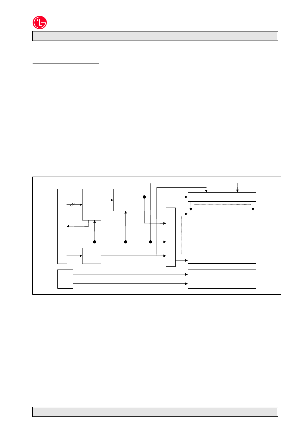
1. General Description
The LG Electronics model LM151X1-G LCD is a Color Active Matrix Liquid Crystal Display with
an integral Cold Cathode Fluorescent Tube(CCFT) back light system. The matrix employs aSi Thin Film Transistor as the active element. It is a transmissive type display operating in the
normally white mode. This TFT-LCD has a 15.1 inch diagonally measured active display area
with XGA resolution(768 vertical by 1024 horizontal pixel array). Each pixel is divided into Red,
Green and Blue sub-pixels or dots which are arranged in vertical stripes. Gray scale or the
brightness of the sub-pixel color is determined with a 8-bit gray scale signal for each dot, thus,
presenting a palette of more than 16,581,375 colors.
LM151X1-G has been designed to apply the interface method that enables low power, high
speed low EMI. Panellink must be used as a LVDS(Low Voltage Differential Signaling) chip.
The LM151X1-G LCD is intended to support applications where high brightness, wide viewing
angle, high color saturation, and high color depth are very important. In combination with
the vertical arrangement of the sub-pixels, the LM151X1-G characteristics provide an
excellent flat panel display for office automation products such as monitors.
General Display Characteristics
The following are general features of the model LM151X1-G LCD;
Active display area 15.1 inches(38cm) diagonal
Outsize dimensions
Pixel pitch
Pixel format 1024 horiz. By 768 vert. pixels
Color depth 8-bit, 16,581,375 colors
Display operating mode transmissive mode, normally white
Surface treatments hard coating(3H),
CN2
CN3
LVDS
4 pairs
V
sync
VCC(3.3V)
VDD(5V)
DC/DC
Block
Timing
Control
Power line for
Digital logic
Analog power line
for TFT-LCD panel
RGB vertical stripe arrangement
anti-glare treatment of the front polarizer
Source driver circuit
Block
1
1
TFT-LCD Panel
(1024
×
768)
768
Backlight Ass’y
352.6w * 264.6h * 16.0t(typ)mm(Without Inverter)
0.30 mm X 0.30 mm
1024
Revision Ver 1.1 October. 19, 1998 Page 4/23
Page 5
LG Electronics Inc.
LM151X1-G
Liquid Crystal Display
Product Specification
2. Maximum Ratings
The following are maximum values which, if exceeded, may cause faulty operation or damage
to the unit.
Table 1 ABSOLUTE MAXIMUM RATINGS
Parameter symbol
Power Input Voltage
Operating Temperature
Storage Temperature
V
DD
V
CC
T
OP
T
ST
Values
Min. Max.
0
-0.3
0
-20
+5.5
+3.6
+50
+60
Units Notes
V
DC
V
DC
at 25 C
at 25 C
deg.
deg.
1
Note: 1. The Relative Humidity must not exceed 95% non-condensing at temperatures of 40¡É or less.
At temperatures greater than 40¡É, the wet bulb temperature must not exceed 39¡É.
3. Electrical Specifications
The LM151X1-G requires three power inputs. Two inputs are employed to power the LCD
electronics and to drive the voltages to drive the TFT array and liquid crystal. And the third
input which powers the backlight CCFL, is typically generated by an inverter. The inverter is
an external unit to the LCD.
Table 2 ELECTRICAL CHARACTERISTICS:
Parameter Symbol
Min. Typ. Max.
MODULE:
Power Supply Input Voltage
Power Supply Input Current
Power Supply Kick-Off Current
V
V
I
VDD
I
Vcc
I
VDD
I
Vcc
DD
CC
4.75
3.15
-
-
-
-
BACK LIGHT
Back light Input voltage
Backlight Input Current
Lamp Kick-Off Voltage
V
BL
I
BL
685
3.0
-
-
1290
1660
Operating Frequency
Life time
F
BL
30
25,000
Notes: 1. VDD input is the analog power supply for the TFT array and liquid crystal, and V
input is the digital logic power supply for the LCD electronics.
2. The input current shall be measured at V
DD
and clock frequency of 65MHz under 9 gray pattern.
3. Power supply kick off current means power supply input current at the moment of
LCM power on. This current is higher then the current at the normal operating
condition and it lasts for 50~100ms.
4. The backlight input current shall be measured at the ground cable and does not
include loss of external inverter.
5. Voltages at both ends of the lamp.
6. Voltages at secondary side of transformer using the balancing capacitor, 22pF in
inverter. These voltages can be changed with customer’s own design of inverter.
7. The life time is defined as the time at which brightness of lamp is 50% compare to
that of initial value at the typical lamp current.
Values
5.0
3.3
800
350
-
-
585
8. 0
-
-
-
-
50
40,000
5.25
3.45
1,200
700
2.0
1.0
570
9.0
880
1145
-
-
80
-
Units Notes
V
DC
V
DC
mA
mA
A
A
V
RMS
mA
V
RMS
V
RMS
V
RMS
V
RMS
At 25 C
At 0 C
At 25 C
At 0 C
KHz
hours
CC
of 5.0Vdc at 25¡É, refresh rate of 60Hz,
1
2
3
4
5
6
7
Revision Ver 1.1 October. 19, 1998 Page 5/23
Page 6
LG Electronics Inc.
LM151X1-G
Liquid Crystal Display
Product Specification
4. Optical Specifications
Optical characteristics are determined after the unit has been ‘ON’ and stable for
approximately 30 minutes in a dark environment at 25C. The values specified are at an
approximate distance 50cm from the LCD surface at a viewing angle of Φ and θ equal to 0°
and aperture 1 degree. The test equipment is PhotoResearch Prichard SpectroRadiometer
Model 1980B-SC or equivalent. The input signal voltage and timing specification are V
5.0Vdc, AVDD of 3.3Vdc and VESA XGA @60Hz respectively. The input current of backlight is
8mA(FBL = 50KHz) at the ground terminals.
Table 2 OPTICAL CHARACTERISTICS
DD
of
Parameter Symbol
Contrast Ratio
Average Brightness, white
Brightness Variation
Response Time
Rise Time
Decay Time
CIE Color Coordinates
Red
Green
Blue
White
Viewing Angle by CR ≥ 10
x axis, right (¥Õ=0º)
x axis, left(¥Õ=180º)
y axis, up(¥Õ=90º)
y axis, down (¥Õ=270º)
Half Luminance Angle
x axis, right (¥Õ=0º)
x axis, left(¥Õ=180º)
y axis, up(¥Õ=90º)
y axis, down (¥Õ=270º)
Cross talk
Flicker
Gamma value
SB
CR
SB
Tr
Tr
Tr
x
y
x
y
x
y
x
y
¥è
¥è
¥è
¥è
¥è
¥è
¥è
¥è
WH
V
R
D
R
R
G
G
B
B
W
W
Values
Min. Typ. Max.
150
170
-
200
200
45
-
-
0.600
0.310
0.270
0.570
0.110
0.070
0.300
0.320
55
55
40
40
10
35
0.630
0.340
0.300
0.600
0.140
0.100
0.320
0.340
60
60
45
45
50
50
40
30
-
-
-
-
-
-
-
-
-
-
-
30
60
15
45
0.660
0.370
0.330
0.630
0.170
0.130
0.340
0.360
-
-
-
-
-
-
-
-
4
-30
-
Units Notes
2
cd/m
%
msec
degree, ¡Æ
degree, ¡Æ
%
dB
1
2
3
4
5
6
7
8
9
Revision Ver 1.1 October. 19, 1998 Page 6/23
Page 7
LG Electronics Inc.
Product Specification
256
512
20mm
20mm
192
384
576
54313121110987621
768
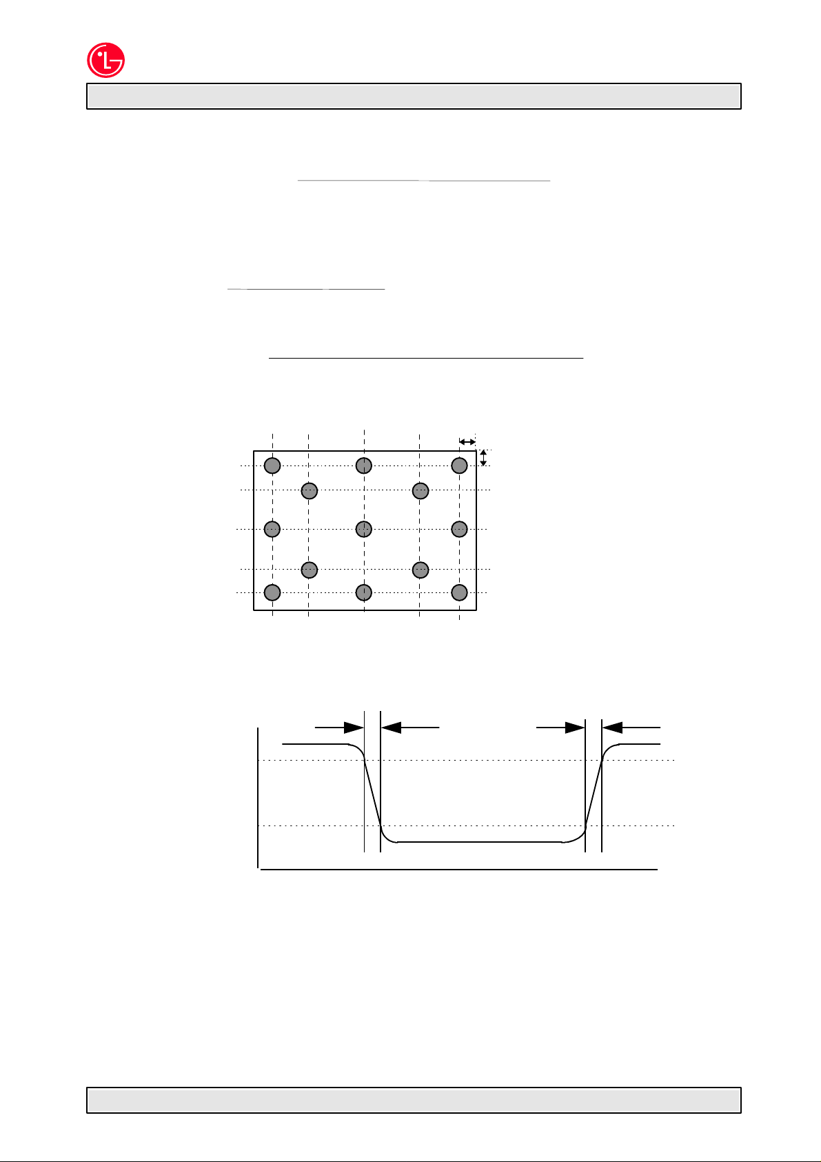
Notes 1. Contrast Ratio (CR) is defined mathematically as:
(Surface Brightness with all white pixels)
(Surface Brightness with all black pixels)
Contrast ratio shall be measured at the center of the display (Location 1).
2. Average Brightness is the average of brightness value at location 1 to 5 with all
pixels displaying white.
B1 + B2 + B3 + B4 + B5
B(AVE) =
5
3. The variation in surface brightness, SBV is defined as :
Maximum (B1, B2, ....B13) - Minimum (B1, B2, ....B13)
Average (B1, B2, .... B5)
Where B1 to B13 are the brightness with all pixels displaying white at 13 locations.
LM151X1-G
Liquid Crystal Display
× 100(%)
( pixel)
4. The response time is defined as the following figure and shall be measured by
switching the input signal for “black” and “white”.
Optical
Response
100
90
10
TrR
%
white
0
black
TrD
white
Revision Ver 1.1 October. 19, 1998 Page 7/23
Page 8
LG Electronics Inc.
LM151X1-G
θ
Liquid Crystal Display
Product Specification
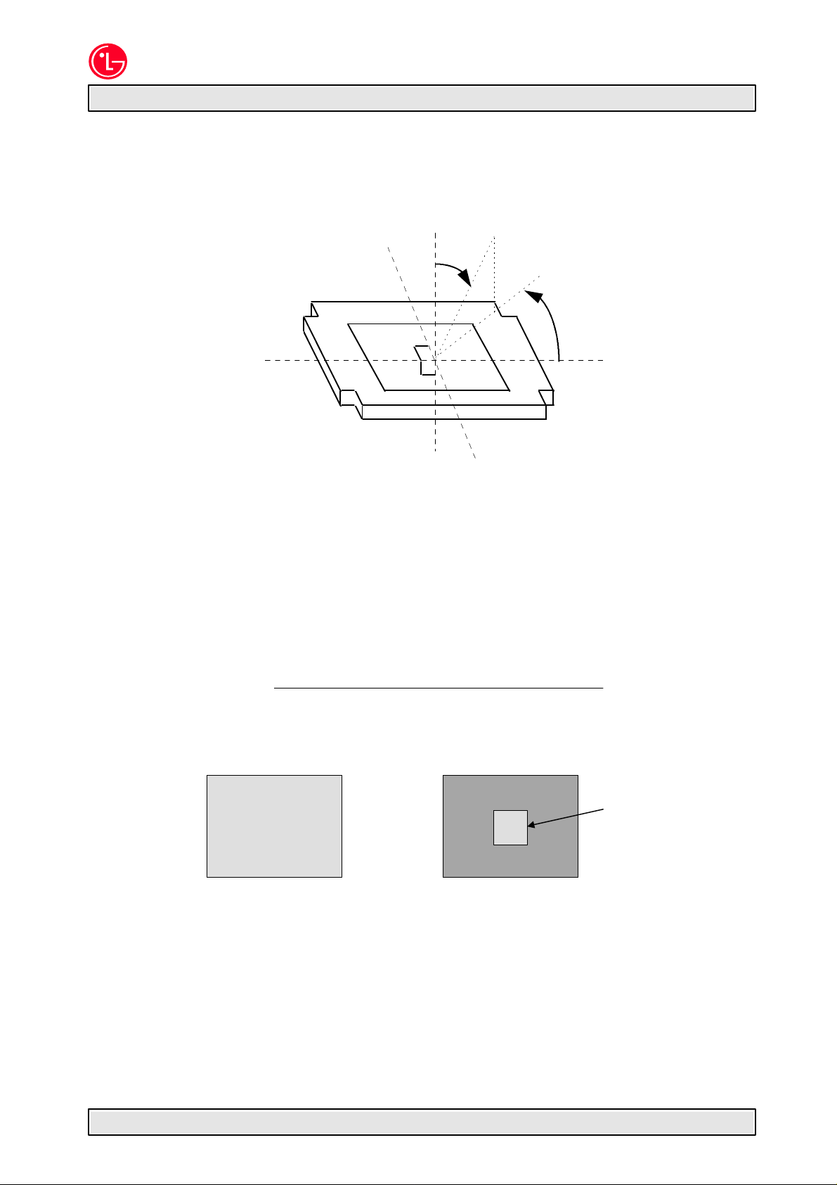
5. Viewing angle is the angle at which the contrast ratio is greater than 10.
= 0¡£
φ = 90¡£
(12:00)
yu
z
A
θ
φ
φ = 180¡£
xl
(9:00)
TFT LCD
MODULE
6. Half Luminance Angles
Half Luminance angles are defined as the up, down, left, and right angular
boundaries at which the luminance value is 50% of the luminance value
measured on-axis.
Measurements shall be done at the center of the display area (Location 1) with
an all white image.
7. Cross talk shall be measured at center location.
Brightness at pattern A - Brightness at pattern B
Crosstalk Ratio =
Brightness at pattern A
Pattern A Pattern B
(Mid-gray : Gs(S)=127) (Background:Gs(S)=0, Rectangular:Gs(S)=127)
z' yd
φ = 0¡£
(3:00) xr
φ = 270¡£
(6:00)
Revision Ver 1.1 October. 19, 1998 Page 8/23
100×100 pixels
Page 9

LG Electronics Inc.
Product Specification
8. Flicker shall be measured at the center location.
Test pattern : Pixel pattern
Background RGB gray ( 0, 0, 0 )
Foreground RGB gray (127,127,127)
AC(at 30Hz)
Test equation : 20 log
DC level
Voltage
LM151X1-G
Liquid Crystal Display
9. Gamma value
n Gs(S)
0 0 - 0.67
1 31 - 1.5
2 63 1.6 4.3
3 95 4.4 10.0
4 127 10.5 18.7
5 159 21.8 32.5
6 191 38.5 52.1
7 223 62.0 76.6
8 255 100 100
DC
Time
Relative Brightness(%)
min max
AC
Remark
Revision Ver 1.1 October. 19, 1998 Page 9/23
Page 10

LG Electronics Inc.
LM151X1-G
Liquid Crystal Display
Product Specification
5. Interface Connections
Interface chip as a transmitter, must be used Panellink ,part No. SiI100, designed by Silicon Image
Inc. or equivalent.
This LCD employs three interface connections, a 21 pin connector is used for the module
electronics and two connectors, a three pin connector, are used for the integral backlight
system.
The electronics interface connector is a model FI-WE21P-HF manufactured by JAE. The pin
configuration for the connector is shown in the table below.
Table 3 MODULE CONNECTOR PIN CONFIGURATION
Pin Symbol Description Notes
1
2
3
4
5
6
7
8
9
10
11
12
13
14
15
16
17
18
19
20
21
GND
V
V
V
GND
GND
AGND
V
R2+
R2V
R1+
R1V
R0+
R0V
RCL+
RCLV
sync
NC
System ground
Analog power supply for TFT array and liquid
DD
crystal
DD
-
DD
System ground
System ground
Analog ground reference for PanelLink
CC
Digital logic power supply for LCD electronics
Plus signal of channel 2 (PanelLink)
Minus signal of channel 2 (PanelLink)
CC
Digital logic power supply for LCD electronics
Plus signal of channel 1 (PanelLink)
Minus signal of channel 1 (PanelLink)
CC
Digital logic power supply for LCD electronics
Plus signal of channel 0 (PanelLink)
Minus signal of channel 0 (PanelLink)
CC
Digital logic power supply for LCD electronics
Plus signal of clock channel (Panel link)
Minus signal of clock channel (Panel link)
Output pin of V
signal for the customer’s usage
sync
No connection
Connect to Vss, see Note 1
+5.0V
+5.0V
+5.0V
Connect to Vss, see Note 1
Connect to Vss, see Note 1
+3.3V
Red data R0 ~ R7, CLT2, DE
See Note 3
+3.3V
Green data G0 ~ G7, CLT0, CLT1
See Note 3
+3.3V
Blue data B0 ~ B7, H
sync
, V
sync
See Note 3
+3.3V
Clock
see Note 4
Notes: 1. All GND(ground) pins should be connected together and to Vss which should also be
connected to the LCD’s metal frame.
2. All VDD and VCC(power input) pins should be connected together respectively.
3. Refer to appendix 1 regarding signal mapping.
4. When VCC is on and H
analog power of LCM(VDD) using this signal(V
is reside, V
sync
can be detected. Customers can control
sync
). Customer can connect with GND or
sync
VCC.
TOP SIDE
BOTTOM SIDE
¡é
¡è
LEFT SIDE OF LCM
PIN 1
The backlight interface connector is a model BHR-03VS-1, manufactured by JST. The mating
connector part number is SM02(8.0)B-BHS-1-TB or equivalent. The pin configuration for the
connector is shown in the table below.
Table 4 BACKLIGHT CONNECTOR PIN CONFIGURATION
Pin Symbol Description Notes
1
2
3
HV
NC
LV
Lamp power input
No connect
Ground
1
2
Revision Ver 1.1 October. 19, 1998 Page 10/23
Page 11

LG Electronics Inc.
LM151X1-G
Liquid Crystal Display
Product Specification
Notes: 1. The input power terminal is colored pink. Ground pin color is light pink.
2. The backlight ground should be common with Vss.
Revision Ver 1.1 October. 19, 1998 Page 11/23
Page 12

LG Electronics Inc.
LM151X1-G
Liquid Crystal Display
Product Specification
6. Signal Timing Specification(Between PanelLink & Timing Controller)
Parameter Symbol
Main
Clock
Frequency
High duration
f
CLK
(=1/t
Low duration
Rise Time
Fall Time
Data Set-up duration
Hold duration
Rise Time
Fall Time
Hsync Period
Pulse Width
Rise/Fall Time
Vsync Period
Pulse Width
Rise/Fall Time
Set-up duration
Data
Enable
Hold duration
Horizontal Back Porch
Horizontal Period
Horizontal Front porch
Vertical Back Porch
Vertical Period
Vertical Front porch
Rise/Fall Time
t
Hsync- Clock phase difference t
Hsync-Vsync phase difference t
t
wcH
t
wcL
t
rCLK
t
fCLK
t
SD
t
HD
t
Dr
t
Df
t
HP
t
WH
t
Hr, tHf
t
VP
t
WV
t
Vr, tVr
t
SI
t
HI
t
HBP
t
HFP
t
VBP
t
VFP
Ir,tIf
HC
HV
CLK
Value
Min. Typ. Max.
)
64.35
0.4 t
0.4 t
-
-
5.0
5.0
-
-
16.25
1056
8
-
CLK
CLK
65.0
0.5 t
0.5 t
20.7
1344
136
CLK
CLK
-
-
-
-
-
-
-
16.7
777
1
-
5
5
8
1056
8
1
777
1
-
t
-10 - t
CLK
806
6
-
-
-
160
1344
24
29
806
3
-
- - tHP-t
65.65
0.6 t
0.6 t
2.3
1.4
4.5
2.1
5
10
5
wcL
Units Notes
CLK
CLK
MHz
ns
ns
65MHz¡¾1%
ns
ns
-
-
-
-
-
ns
ns
ns
ns
§Á
clock
clock
for f
CLK
for f
CLK
CL =15pF
CL =15pF
ns
-
-
-
msec
lines
lines
ns
-
-
-
-
-
-
-
-
ns
ns
clock
clock
clock
lines
lines
lines
for f
for f
CLK
CLK
ns
ns
WH
ns
Revision Ver 1.1 October. 19, 1998 Page 12/23
Page 13

LG Electronics Inc.
Product Specification
Dr
t
LM151X1-G
Liquid Crystal Display
7. Signal Timimg Waveforms
tHf, t
Vf
tIf, t
Df
Main
Clock
0.5V
Hsync, Vsync,
Data, Data
t
t
CLK
DD
0.5V
DD
0.2V
DD
WCH
0.7V
DD
0.9V
DD
0.2V
DD
0.1VDD0.1V
t
SD
t
HD
0.9V
DD
0.1V
DD
t
WCL
DD
t
fCLK
0.9V
0.1V
Data
(R0~R7,
Invalid Data Invalid Data
G0~G7,
B0~B7)
t
DataEnable
HI
0.7V
DD
0.2V
DD
0.7V
DD
Main
Clock
t
HC
tHr, t
Vr
tIr, t
t
rCLK
0.9V
0.1V
DD
DD
DD
DD
Hsync
Vsync
Hsync
DataEnable
Vsync
DataEnable
0.2V
0.2V
0.2V
DD
t
HV
0.2V
DD
t
HP
t
WH
0.7V
DD
DD
DD
0.2V
DD
t
HBP
0.7V
DD
t
VP
t
t
WV
WV
0.7V
DD
0.2V
DD
t
VBP
0.2V
DD
0.7V
t
t
0.2V
HFP
0.2V
VFP
DD
DD
DD
Revision Ver 1.1 October. 19, 1998 Page 13/23
Page 14

LG Electronics Inc.
LM151X1-G
Liquid Crystal Display
Product Specification
8. Color Input Data Reference
The brightness of each primary color(red, green and blue) is based on the 8-bit gray scale data
input for the color; the higher the binary input, the brighter the color. The table below provides
a reference for color versus data input.
Table 5 COLOR DATA REFERENCE
Input Color Data
Basic
Colors
Red
Green
Blue
Color Red
MSB LSB
R7 R6 R5 R4 R3 R2 R1 R0
Black
Red(255)
Green(255)
Blue(255)
Cyan
Magenta
Yellow
White
Red(000) Dark
Red(001)
Red(002)
Red(253)
Red(254)
Red(255) Bright
Green(000)Dark
Green(001)
Green(002)
Green(253)
Green(254)
Green(255)Bright
Blue(000) Dark
Blue(001)
Blue(002)
Blue(253)
Blue(254)
Blue(255) Bright
0
0
0
1
1
1
0
0
0
0
0
0
0
0
0
1
1
1
1
1
1
1
1
1
0
0
0
0
0
0
0
0
0
:
:
:
1
1
1
1
1
1
1
1
1
0
0
0
0
0
0
0
0
0
:
:
:
0
0
0
0
0
0
0
0
0
0
0
0
0
0
0
0
0
0
:
:
:
0
0
0
0
0
0
0
0
0
MSB LSB
G7 G6 G5 G4 G3 G2 G1 G0
0
0
0
0
0
0
1
1
1
1
1
0
0
0
0
0
0
1
0
0
0
0
0
0
0
0
0
0
0
1
1
1
1
1
1
0
1
1
1
1
1
1
1
1
1
1
1
1
0
0
0
0
0
0
0
0
0
0
1
0
0
0
0
1
0
0
:
:
:
:
:
:
1
1
1
0
1
0
1
1
1
1
0
0
1
1
1
1
1
0
0
0
0
0
0
0
0
0
0
0
0
0
0
0
0
0
0
0
:
:
:
:
:
:
0
0
0
0
0
1
0
0
0
0
0
1
0
0
0
0
0
1
0
0
0
0
0
0
0
0
0
0
0
0
0
0
0
0
0
0
:
:
:
:
:
:
0
0
0
0
0
0
0
0
0
0
0
0
0
0
0
0
0
0
Green
MSB LSB
B7 B6 B5 B4 B3 B2 B1 B0
0
0
0
0
0
0
0
0
0
0
0
0
0
0
0
0
1
1
1
1
1
1
1
0
0
0
0
0
0
0
0
1
1
1
1
1
1
1
1
1
0
0
0
0
0
0
0
1
1
1
1
1
1
1
1
0
1
1
1
1
1
1
1
1
0
0
0
0
0
0
0
0
0
0
0
0
0
0
0
0
0
0
0
0
0
0
0
0
:
:
:
:
:
:
:
:
0
0
0
0
0
0
0
0
0
0
0
0
0
0
0
0
0
0
0
0
0
0
0
0
0
0
0
0
0
0
0
0
0
0
0
0
0
0
1
0
0
0
0
0
0
1
0
0
:
:
:
:
:
:
:
:
1
1
1
1
1
0
1
0
1
1
1
1
1
1
0
0
1
1
1
1
1
1
1
0
0
0
0
0
0
0
0
0
0
0
0
0
0
0
0
0
0
0
0
0
0
0
0
0
:
:
:
:
:
:
:
:
0
0
0
0
0
0
0
1
0
0
0
0
0
0
0
1
0
0
0
0
0
0
0
1
Blue
0
0
0
0
0
0
0
0
0
0
0
0
0
0
0
0
0
0
1
1
1
1
1
1
1
1
1
1
1
1
1
1
1
1
1
1
0
0
0
0
0
0
1
1
1
1
1
1
0
0
0
0
0
0
0
0
0
0
0
0
0
0
0
0
0
0
:
:
:
:
:
:
0
0
0
0
0
0
0
0
0
0
0
0
0
0
0
0
0
0
0
0
0
0
0
0
0
0
0
0
0
0
0
0
0
0
0
0
:
:
:
:
:
:
0
0
0
0
0
0
0
0
0
0
0
0
0
0
0
0
0
0
0
0
0
0
0
0
0
0
0
0
0
0
0
0
0
0
0
1
:
:
:
:
:
:
1
1
1
1
1
0
1
1
1
1
1
1
1
1
1
1
1
1
0
0
0
1
1
1
0
1
0
0
0
:
0
0
0
0
0
0
:
0
0
0
0
1
0
:
1
0
1
Revision Ver 1.1 October. 19, 1998 Page 14/23
Page 15

LG Electronics Inc.
9. Power Sequences
LM151X1-G
Liquid Crystal Display
Product Specification
Power Supply, V
CC
for Digital Logic
Power Supply , V
for Analog Circuits
Interface Signal, V
(Digital RGB signal,
V
, H
sync
, DE, Clock
sync
to PanelLink
Power Supply for
Backlight Inverter
DD
90%90%
0V
0V
i
10% 10%
T
1
Customers can monitor V
T
2
90%
10%
T
1
T
4
T
T
3
1
Valid
T
2
Invalid Period
(Monitoring V
T
sync
5
sync
with V
)
CC
Valid
T
1
T
2
T
4
n T1 : 10 ns ~ 20 ms (Rise time, Fall time of power supplies)
n T2 : 100 ms (min.)
n T3 : ~100 ms
n T4 : 100 ms (max.)
n T5 : 500 ms (min.)
Notes: 1. Please avoid floating state of interface signal at invalid period.
2. When the interface signal is invalid or no signal, be sure to pull down the analog
power supply for LCD panel, VDD to 0V. Invalid signal with VDD for a long period of time,
cause permanent damage to LCD panel.
3. BackLight inverter power must be turn on after power supply for LCD and interface
signal are valid.
Revision Ver 1.1 October. 19, 1998 Page 15/23
Page 16

LG Electronics Inc.
LM151X1-G
Liquid Crystal Display
Product Specification
10. Mechanical Characteristics
The chart below provides general mechanical characteristics for the model LM151X1-G LCD.
Please refer to appendix 2 regarding the detailed mechanical drawing of the LCD module.
Parameter Value Symbol Notes
Outside dimension
Width
Height
Thickness
Bezel area
Width
Height
Active area
Width
Height
352.6 (typ)
264.6 (typ)
16.0 (typ)
311.2
234.4
307.2
230.4
mm
mm
mm
Weight
Front surface of LCD
1500(typ)
1600 (max)
Hard coating 3H.
Anti-glare treatment
of the front polarizer
gram
-
Revision Ver 1.1 October. 19, 1998 Page 16/23
Page 17

LG Electronics Inc.
Product Specification
11. Environmental Specification
No Test ITEM Conditions
1 Temperature
Operating
Non-operating
0 C ~ 50 C
-20 C ~ 60 C
LM151X1-G
Liquid Crystal Display
Operating
2 Humidity
3 Altitude
4
5
Vibration test
(non-operating)
(non-operating)
Non-operating
Shock test
20% ~ 80% RH (non-condensing)
5% ~ 95% RH
(38.7¡É maximum wet bulb temperature)
Operating : 12,000ft
Storage : 40,000ft
Waveform : Random
Vibration level : 1.5G RMS
Bandwidth : 10~200Hz
Duration : X, Y, Z 20 min
one time each direction
Shock level : 100G
Waveform: half sine wave, 2ms
Direction : X, Y, Z
one time each direction
Revision Ver 1.1 October. 19, 1998 Page 17/23
Page 18

LG Electronics Inc.
LM151X1-G
Liquid Crystal Display
Product Specification
12. Designation of Lot Mark
a) Lot Mark
KJIHGFEDCBA L
A, B : DIVISION CODE
C, D, E : MODEL CODE
F : YEAR
G : MONTH
H, I, J, K, L : SERIAL NO.
Note : 1. YEAR
YEAR 89 90 91 92 93 94 95 96 97 98 99
Mark 9 0 1 2 3 4 5 6 7 8 9
2. MONTH
MONTH Jan. Feb. Mar. Apr. May Jun. Jun. Aug. Sep. Oct. Nov. Dec.
Mark 1 2 3 4 5 6 7 8 9 0 N D
b) Location of Lot Mark
Serial NO. Is printed on the label. The label is attached to the backside of the LCD module.
This is subject to change without prior notice.
13. Packing Form
a) Package quantity in one box : 8 pcs
b) Box Size : 587mm¡¿408mm¡¿378mm
Note : 1. Please, refer to appendix 3 regarding the detailed packing assembly drawing.
Revision Ver 1.1 October. 19, 1998 Page 18/23
Page 19

LG Electronics Inc.
Product Specification
LM151X1-G
Liquid Crystal Display
14. PRECAUTIONS
Please pay attention to the followings when you use this TFT-LCD module with Back-light unit.
1)You must mount Module using mounting holes arranged in 4 corners.
2) Be sure to turn off the power when connecting or disconnecting the circuit.
3) Note that the polarizers are easily damaged. Pay attention not to scratch or press this
surface with any hard object.
4) When the LCD surface become dirty, please wipe it off with a soft material. (ie. cotton ball)
5) Protect the module from the ESD as it may damage the electronic circuit
(C-MOS). Make certain that treatment person’s body are grounded through
wrist bend.
6) Do not disassemble the module and be careful not to incur a mechanical shock that
might occur during installation. It may cause permanent damage.
7) Do not leave the module in high temperatures, particularly in areas of high humidity for a
long time.
8) The module not be expose to the direct sunlight.
9) Avoid contact with water as it may a short circuit within the module.
10) Do not apply invalid signal, especially very high frequency data clock and Hsync. Invalid
signal causes improper shutdown of DC/DC converter in LCM or permanent damage to LCD
module.(If DC/DC converter in LCM is in shutdown state, LCM shows only white screen. Then
please turn off and on once LCM power.)
Revision Ver 1.1 October. 19, 1998 Page 19/23
Page 20

LG Electronics Inc.
LM151X1-G
Liquid Crystal Display
Product Specification
15.
APPENDIX 1 : Required Signal Assignment for PanelLink Tx, SiI100
Pin # Pin Name Require Signals Pin # Pin Name Require Signals
1 DE Data Enable 33 EXT_RES Voltage Swing Adjust
2 LP Horizontal Sync (Hsync) 34 SUPV Input threshold voltage control
3 FLM Vertical Sync (Vsync) 35 PD Power Down Mode (Active Low)
4 GND Digital Ground 36 SYNCOUT PLL Synchronization Signal
5 CLT0 Should be connected to pin 36 (SYNCOUT) 37 P23 R7 (MSB)
6 CLT1 - 38 P22 R6
7 CLT2 - 39 VCC Core Digital V
8 CLT3 - 40 P21 R5
9 DEDGE Clock latching edge for data 41 P20 R4
10 VCC Core Digital V
11 CEDGE
12 DCLK Pixel Clock 44 P17 R1
13 HALFCK - 45 GND Digital Ground
14 SYNC_CONT - 46 P16 R0 (LSB)
15 PLLCK Test Pin 47 P15 G7 (MSB)
16 GND Digital Ground 48 P14 G6
17 PGND PLL Analog Ground 49 P13 G5
18 PVCC PLL Analog V
19 AGND Transmitter Analog Ground 51 P11 G3
20 TXC-
21 TXC+
22 AVCC Transmitter Analog V
23 TX0-
24 TX0+
25 AGND Transmitter Analog Ground 57 P6 B6
26 TX1-
27 TX1+
28 AVCC Transmitter Analog V
29 TX2-
30 TX2+
31 AGND Transmitter Analog Ground 63 P0 B0 (LSB)
32 VCC Core Digital V
Clock latching edge for DE, Hsync, Vsync,
Low Voltage swing differential output clock
Low Voltage swing differential output clock
Low Voltage swing differential output data
pairs
Low Voltage swing differential output data
pairs
Low Voltage swing differential output data
pairs
Low Voltage swing differential output data
pairs
Low Voltage swing differential output data
pairs
Low Voltage swing differential output data
pairs
CC
CLT
CC
pair
pair
CC
CC
CC
42 P19 R3
43 P18 R2
50 P12 G4
52 P10 G2
53 IVCC
54 P9 G1
55 P8 G0 (LSB)
56 P7 B7 (MSB)
58 P5 B5
59 P4 B4
60 P3 B3
61 P2 B2
62 P1 B1
64 GND Digital Ground
Power Supply for Input Signal (3.3V or
CC
5V)
Notes : Refer to SiI100 Data Sheet for detail descriptions.
Revision Ver 1.1 October. 19, 1998 Page 20/23
Page 21

LG Electronics Inc.
16.
APPENDIX 2 : Outline Drawing
LM151X1-G
Liquid Crystal Display
Product Specification
Revision Ver 1.1 October. 19, 1998 Page 21/23
Page 22

LG Electronics Inc.
Product Specification
LM151X1-G
Liquid Crystal Display
Revision Ver 1.1 October. 19, 1998 Page 22/23
Page 23

LG Electronics Inc.
Product Specification
17. APPENDIX 3 : Packing Assembly Drawing
LM151X1-G
Liquid Crystal Display
Revision Ver 1.1 October. 19, 1998 Page 23/23
Page 24

LG Electronics Inc.
Product Specification
LM151X1-G
Liquid Crystal Display
Revision Ver 1.1 October. 19, 1998 Page 24/23
 Loading...