

Page 1
6
Analog power line
Timing
Control
LiquidCrystal Display
Product General Specification
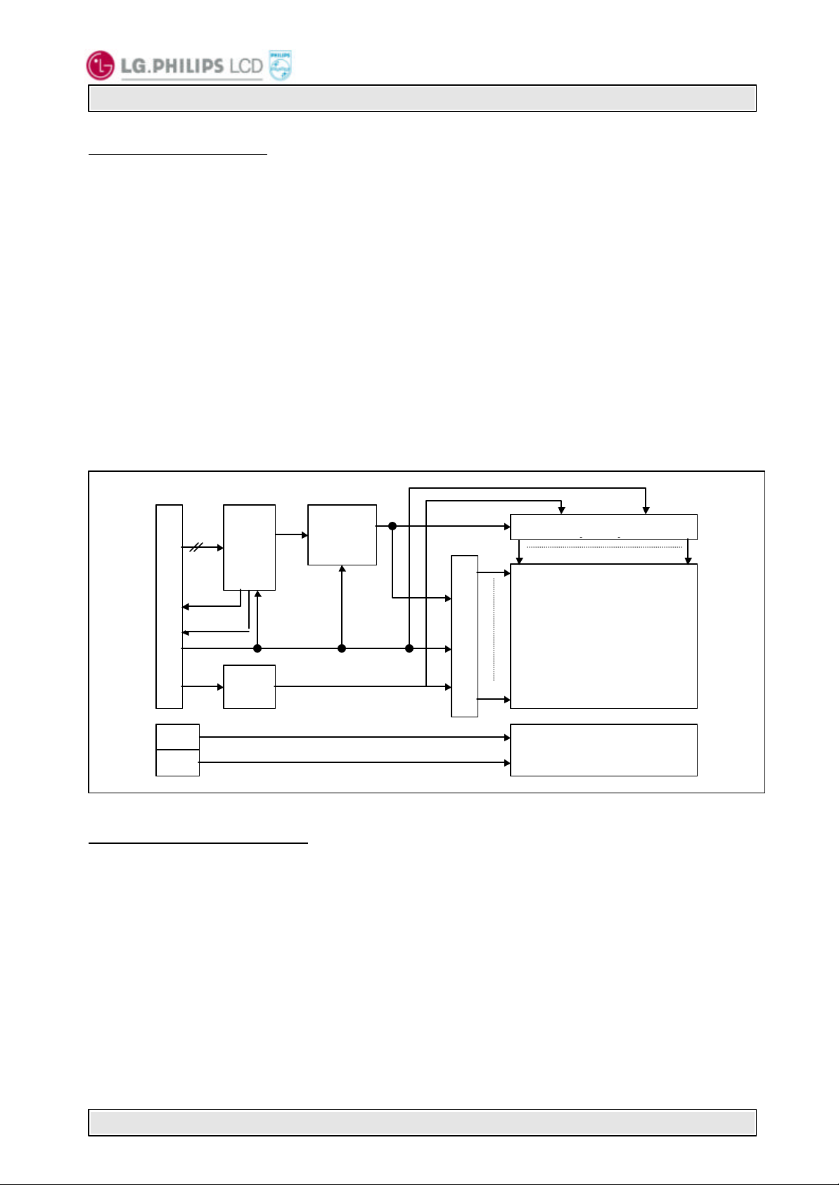
1. General Description
LM151X1
The LM151X1 LCD is a Color Active Matrix Liquid Crystal Display with an integral Cold Cathode
Fluorescent Tube(CCFT) back light system. The matrix employs a-Si Thin Film Transistor as the
active element. It is a transmissive type display operating in the normally white mode. This
TFT-LCD has a 15.1 inch diagonally measured active display area with XGA resolution(768
vertical by 1024 horizontal pixel array). Each pixel is divided into Red, Green and Blue subpixels or dots which are arranged in vertical stripes. Gray scale or the brightness of the subpixel color is determined with a 8-bit gray scale signal for each dot, thus, presenting a palette
of more than 16,777,216 colors.
LM151X1 has been designed to apply the interface method that enables low power, high
speed low EMI. Panellink must be used as a LVDS(Low Voltage Differential Signaling) chip.
The LM151X1 LCD is intended to support applications where high brightness, wide viewing
angle, high color saturation, and high color depth are very important. In combination with
the vertical arrangement of the sub-pixels, the LM151X1-D2MN characteristics provide an
excellent flat panel display for office automation products such as monitors.
CN1 connector(21pin)
LVDS
4 pairs
V
sync
H
sync
PanelLin
k
Power line for
Digital logic VCC(3.3V)
Block
Source driver
1
1
Gate Driver
TFT- LCD Panel
(1024×768)
VDD(5V)
DC/D
C
for TFT-LCD panel
CN2
Backlight Ass’y
CN3
General Display Characteristics
The following are general features of the model LM151X1 LCD;
Active display area 15.1 inches(38cm) diagonal
Outsize dimensions 352.6w * 264.6h * 16.0t(typ)mm(Without Inverter)
Pixel pitch 0.30 mm × 0.30 mm
Pixel format 1024 horiz. By 768 vert. pixels
RGB vertical stripe arrangement
Color depth 8-bit, 16,777,216 colors
Display operating mode transmissive mode, normally white
Surface treatments hard coating(3H),
anti-glare treatment of the front polarizer
Revision Ver 1.2 July 11, 2000 Page 1/6
Page 2
6
LiquidCrystal Display
Product General Specification
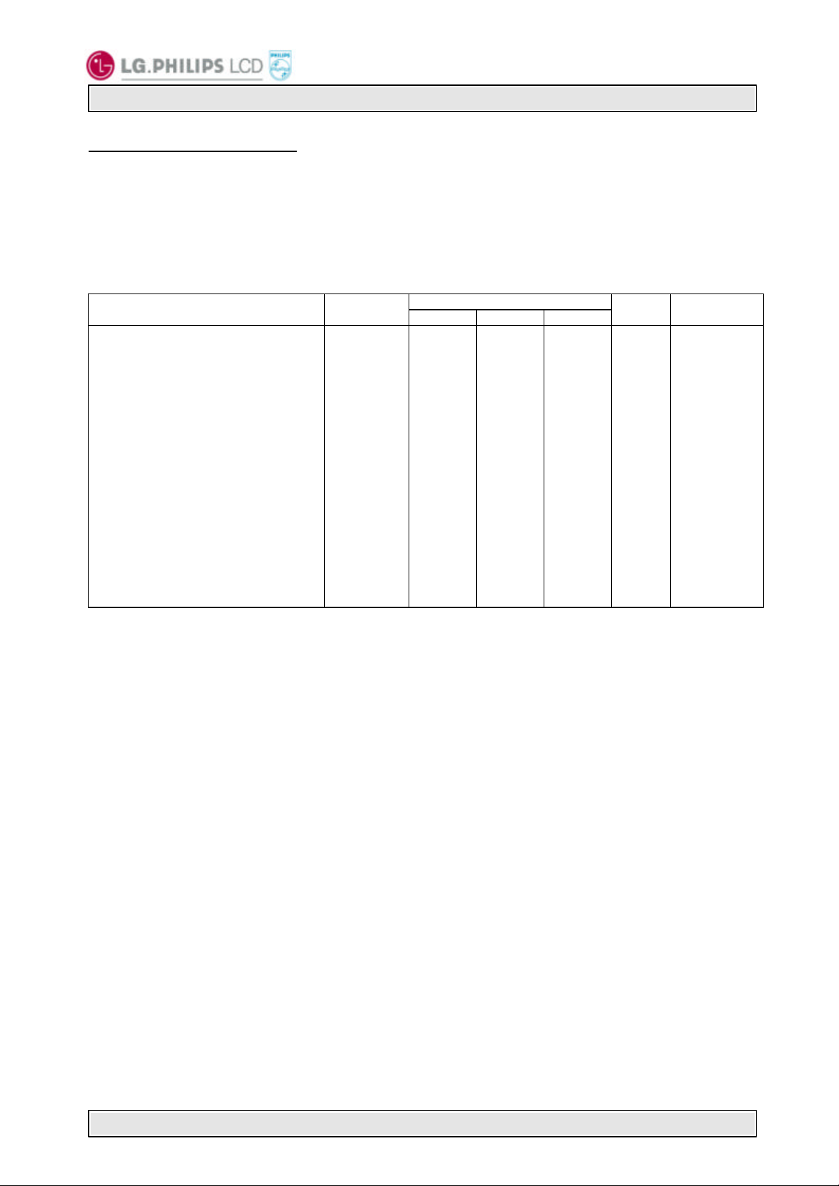
2. Electrical Specifications
2 - 1 Electrical Characteristics
The LM151X1 requires three power inputs. Two inputs are employed to power the LCD
electronics and to drive the voltages to drive the TFT array and liquid crystal. And the third
input which powers the backlight CCFL, is typically generated by an inverter. The inverter is an
external unit to the LCD.
Table1 ELECTRICAL CHARACTERISTICS:
LM151X1
Parameter Symbol
MODULE:
Power Supply Input Voltage
Power Supply Input Current
Power Supply Kick -Off Current
BACK LIGHT
Back light Input voltage
Backlight Input Current
Lamp Kick -Off Voltage
Operating Frequency
Life time
V
DD
V
CC
I
VDD
I
Vcc
I
VDD
I
Vcc
V
BL
IBL
FBL
Min. Typ. Max.
4.75
3.15
-
-
-
-
685
3.0
-
-
1290
1660
30
25,000
Notes: 1. VDD input is the analog power supply for the TFT array and liquid crystal, and VCC
input is the digital logic power supply for the LCD electronics.
2. The input current shall be measured at V
DD
and clock frequency of 65MHz under 9 gray pattern.
3. Power supply kick off current means power supply input current at the moment of
LCM power on. This current is higher then the current at the normal operating
condition and it lasts for 50~100ms.
4. The backlight input current shall be measured at the ground cable and does not
include loss of external inverter.
5. Voltages at both ends of the lamp.
6. Voltages at secondary side of transformer using the balancing capacitor, 22pF in
inverter. These voltages can be changed with customer ’s own design of inverter.
7. The life time is defined as the time at which brightness of lamp is 50% compare to
that of initial value at the typical lamp current on condition of continuous
operating at 25±2℃.
Values
5.0
3.3
360
230
-
-
585
8.0
-
-
-
-
50
40,000
5.25
3.45
500
300
1.2
0.6
570
9.0
880
1145
-
-
80
-
Units Notes
VDC
V
DC
mA
1
2
mA
A
3
A
V
RMS
mA
V
RMS
V
RMS
V
RMS
V
RMS
4
At 25±2℃
At 0±2℃
5
At 25±2℃
At 0±2℃
6
KHz
hours
7
of 5.0Vdc at 25℃, refresh rate of 60Hz,
Revision Ver 1.2 July 11, 2000 Page 2/6
Page 3

6
PIN 21
PIN 20
PIN 2
LiquidCrystal Display
Product General Specification
2 - 2 Interface Connections
This LCD employs three interface connections, a 21 pin connector is used for the module
electronics and two connectors, a three pin connector, are used for the integral backlight system.
Interface chip as a transmitter, must be used Panellink ,part No. SiI100, designed by Silicon Image
Inc. or equivalent.
The electronics interface connector is a model FI-WE21P-HF manufactured by JAE. The pin
LM151X1
configuration for the connector is shown in the table below.
Table 2 MODULE CONNECTOR PIN CONFIGURATION
Pin Symbol Description Notes
1
2
3
4
5
6
7
8
9
10
11
12
13
14
15
16
17
18
19
20
21
GND
VDD
VDD
VDD
GND
GND
GND
VCC
R2+
R2VCC
R1+
R1VCC
R0+
R0-
H
sync
RCL+
RCL-
V
sync
NC
System ground
Analog power supply for TFT array and liquid crystal
-
System ground
System ground
System ground
Digital logic power supply
Plus signal of channel 2 (PanelLink)
Minus signal of channel 2 (PanelLink)
Digital logic power supply
Plus signal of channel 1 (PanelLink)
Minus signal of channel 1 (PanelLink)
Digital logic power supply
Plus signal of channel 0 (PanelLink)
Minus signal of channel 0 (PanelLink)
Output pin of H
signal for the customer ’s usage
sync
Plus signal of clock channel (PanelLink)
Minus signal of clock channel (PanelLink)
Output pin of V
signal for the customer ’s usage
sync
No Connection
Notes: 1. All GND(ground) pins should be connected to the LCD’s metal frame.
2. Refer to the data sheet of PanelLink transmitter SiI100.
3. Pins for DPMS. When VCC is on, V
sync
width
is always fixed about 1.1usec independent of HSYNC coming from VGA controller.
TOP SIDE ↓
LEFT SIDE OF LCM
BOTTOM SIDE ↑
The backlight interface connector is a model BHR-03VS-1, manufactured by JST. The mating
connector part number is SM02(8.0)B-BHS-1-TB or equivalent. The pin configuration for the
connector is shown in the table below.
Table 3 BACKLIGHT CONNECTOR PIN CONFIGURATION
Pin Symbol Description Notes
1
2
3
HV
NC
LV
Notes: 1. The input power terminal is colored pink. Ground pin color is light pink.
and H
are available. In case HSYNC output, sync
sync
Lamp power input
No connect
Ground
see Note 1
+5.0V
+5.0V
+5.0V
see Note 1
see Note 1
see Note 1
+3.3V
R0~R7,CLT2,DE, See Note 2
+3.3V
G0 ~ G7, CLT0, CLT1, See Note 2
-
+3.3V
B0 ~ B7, H
sync
, V
,See Note 2
sync
see Note 3
Main Clock, See Note 2
see Note 3
PIN 1
1
2
Revision Ver 1.2 July 11, 2000 Page 3/6
Page 4

6
< Front View >
LM151X1
LiquidCrystal Display
Product General Specification
Revision Ver 1.2 July 11, 2000 Page 4/6
Page 5

6
< Rear View >
LM151X1
LiquidCrystal Display
Product General Specification
Revision Ver 1.2 July 11, 2000 Page 5/6
Page 6

6
Product General Specification
LM151X1
LiquidCrystal Display
3 .PRECAUTIONS
The LCD Products listed on this documents are not suitable for use of Military,Industry,Medical etc.
system.
If customers intend to use these LCD products for above application, please contact ours sales
people in advance.
Revision Ver 1.2 July 11, 2000 Page 6/6
 Loading...