

LG Chem 6.4 EX Installation Manual

Residential Energy Storage Unit
6.4 EX Battery Pack
For Photovoltaic Systems
Installation Manual
September 2015 | Edition 2

This manual describes how to safely install the RESU®6.4 EX battery pack
from LG Chem.
Read this manual thoroughly before you attempt to install the product, and
follow the instructions carefully throughout the installation process.
If you are uncertain about any of the requirements, recommendations, or
safety procedures described in this manual, contact LG Chem immediately
for advice and clarication.
NOTE
The information included in this document is accurate at the time of publi-
cation. However, this product is subject to change without prior notice. In
addition, the illustrations in this document are meant only to help explain
system congurationconcepts and installation instructions. The illustrated
items may dier from the actual items at the installation location.

Contents
1 Introduction 5
1.1 Features . . . . . . . . . . . . . . . . . . . . . . . . . . . . . . . . 5
1.2 Package Items . . . . . . . . . . . . . . . . . . . . . . . . . . . . . 5
Main battery pack . . . . . . . . . . . . . . . . . . . . . . . . . . . 5
Expansion battery pack . . . . . . . . . . . . . . . . . . . . . . . . 6
1.3 LED Indicators . . . . . . . . . . . . . . . . . . . . . . . . . . . . . 7
Main battery pack . . . . . . . . . . . . . . . . . . . . . . . . . . . 7
Expansion battery pack . . . . . . . . . . . . . . . . . . . . . . . . 7
1.4 Specications . . . . . . . . . . . . . . . . . . . . . . . . . . . . . 8
2 Safety 11
2.1 General Precautions for the Battery Pack . . . . . . . . . . . . . . 11
2.2 Tools . . . . . . . . . . . . . . . . . . . . . . . . . . . . . . . . . . 12
2.3 Safety Gear . . . . . . . . . . . . . . . . . . . . . . . . . . . . . . . 12
2.4 Warning Labels . . . . . . . . . . . . . . . . . . . . . . . . . . . . 13
Main battery pack . . . . . . . . . . . . . . . . . . . . . . . . . . . 13
Expansion battery pack . . . . . . . . . . . . . . . . . . . . . . . . 14
3 Installation 15
3.1 Installation Location . . . . . . . . . . . . . . . . . . . . . . . . . 15
3.2 Installing the Main Battery Pack . . . . . . . . . . . . . . . . . . . 16
Securing the battery pack to a wall . . . . . . . . . . . . . . . . . 16
Connecting the battery pack to the inverter . . . . . . . . . . . . 18
3.3 Installing the Expansion Battery Pack . . . . . . . . . . . . . . . 22
Connecting an expansion pack to the main pack . . . . . . . . . 22
Securing the expansion pack to a wall . . . . . . . . . . . . . . . 27
3.4 Checking Before Operation . . . . . . . . . . . . . . . . . . . . . 29
Circuit breaker switch . . . . . . . . . . . . . . . . . . . . . . . . 29
Circuit breaker’s trip button . . . . . . . . . . . . . . . . . . . . . 29
Voltage . . . . . . . . . . . . . . . . . . . . . . . . . . . . . . . . . 30
3.5 Starting the Battery Pack . . . . . . . . . . . . . . . . . . . . . . . 31
3.6 Shutting Down the Battery Pack . . . . . . . . . . . . . . . . . . . 31
4 Troubleshooting 32
3

Contents
4.1 Main Battery Pack . . . . . . . . . . . . . . . . . . . . . . . . . . . 32
4.2 Expansion Battery Pack . . . . . . . . . . . . . . . . . . . . . . . . 33
5 Emergency Situations 34
5.1 Leaking Batteries . . . . . . . . . . . . . . . . . . . . . . . . . . . 34
5.2 Fire . . . . . . . . . . . . . . . . . . . . . . . . . . . . . . . . . . . 34
5.3 Wet Batteries . . . . . . . . . . . . . . . . . . . . . . . . . . . . . . 35
5.4 Damaged Batteries . . . . . . . . . . . . . . . . . . . . . . . . . . 35
6 Warranty 36
6.1 Warranty Coverage . . . . . . . . . . . . . . . . . . . . . . . . . . 36
6.2 Limitation of Liability . . . . . . . . . . . . . . . . . . . . . . . . 36
6.3 Contact Information . . . . . . . . . . . . . . . . . . . . . . . . . 36
A Technical Information 37
A.1 Main Battery Pack . . . . . . . . . . . . . . . . . . . . . . . . . . . 38
A.2 Expansion Battery Pack . . . . . . . . . . . . . . . . . . . . . . . . 39
A.3 Main Pack plus 1 Expansion Pack . . . . . . . . . . . . . . . . . . 39
A.4 Main Pack plus 2 Expansion Packs . . . . . . . . . . . . . . . . . 39
A.5 Compatible Inverters . . . . . . . . . . . . . . . . . . . . . . . . . 40
4
1 Introduction
1.1 Features
The RESU®6.4 EX battery pack has the following features:
Photovoltaic system: This battery pack is designed for photovoltaic system
compatibility.
Battery management system (BMS): The battery pack’s built-in BMS moni-
tors its operation and prevents the battery from operating outside design
limitations. See Troubleshooting on page 32.
Expandability: The battery capacity can be increased by adding expansion
battery packs. Up to two expansion battery packs can be added. An ex-
pansion battery pack can be purchased either with the main battery pack
or as a separate unit. See Installing the Expansion Battery Pack on page
22.
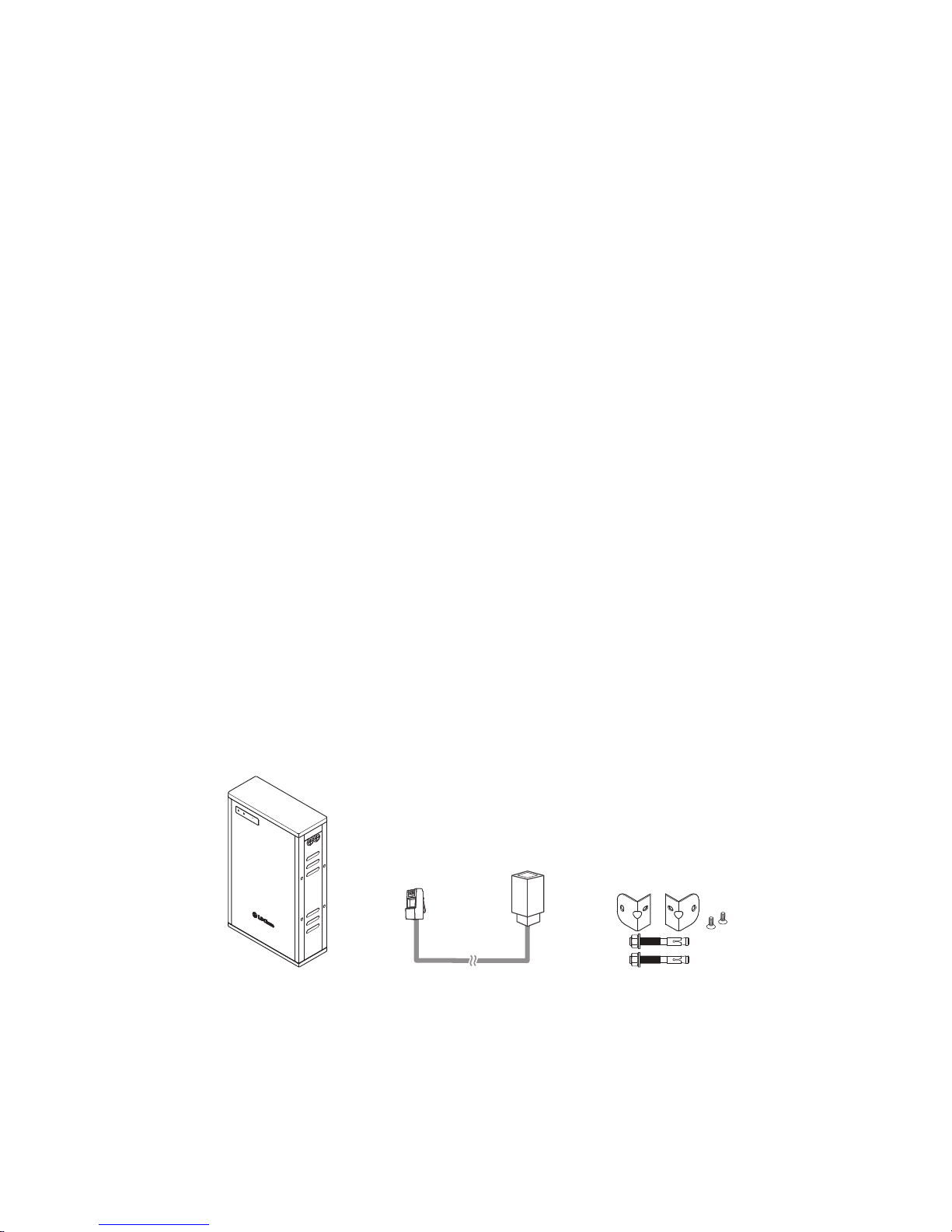
1.2 Package Items
Main battery pack
Items other than those listed below, such as a power cable, may be provided
separately.
Status
Charge / Discharge
RESU 6.4
R
Main battery pack Communication cable
adapter
Mounting brackets
For details on how these items are used, see Installation on page 15.
5
Introduction
NOTE
A tag is attached to the gender changer side of the provided communi-
cation cable adapter. The tag is labeled as TYPE-S or TYPE-N. TYPE-S
adapters are used with most inverters, including SMA inverters, whereas
TYPE-N adapters are supposed to be used only with Nedap inverters. If
the wrong cable adapter is identied, contact LG Chem or your distributor.
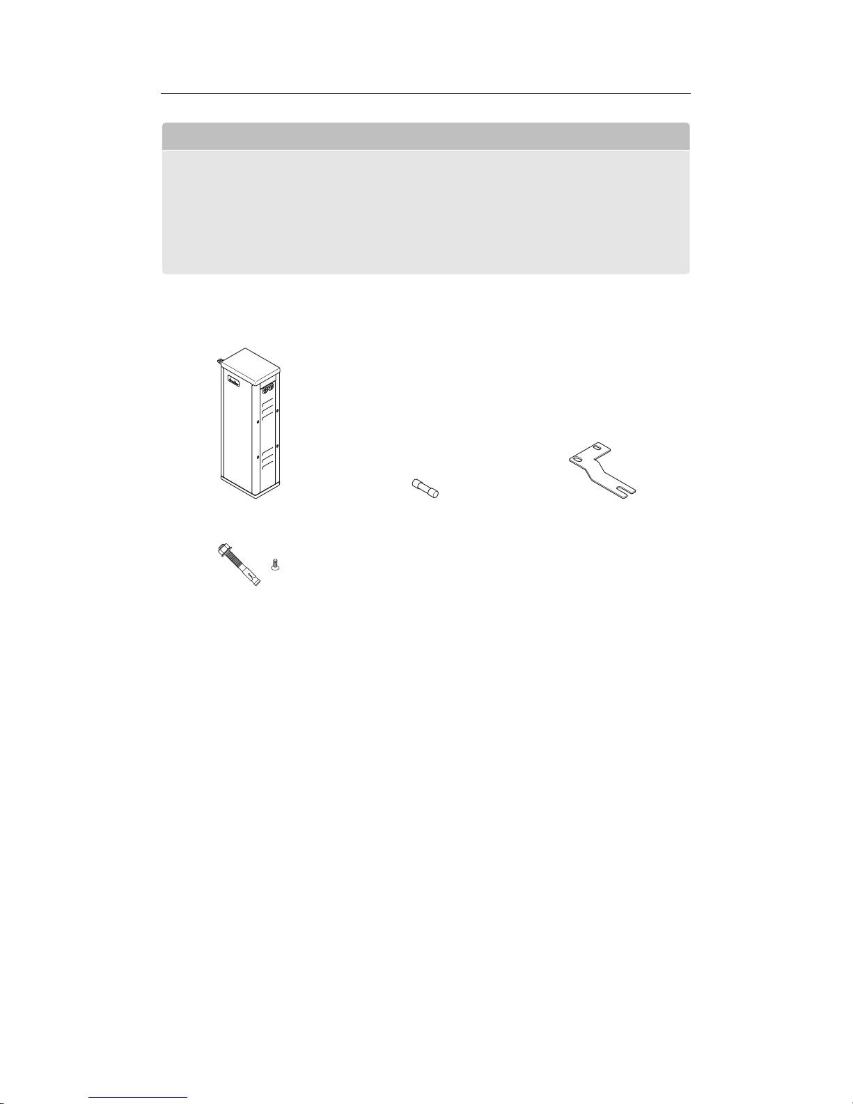
Expansion battery pack
Expansion battery pack Fuse Connecting brackets
Anchor bolt for mounting
1)
1)
When an expansion battery pack is later installed, if it is dicult to reuse the anchor bolt and
mounting bolt used on the right side of the main battery pack, use these bolts.
For details on how these items are used, see Installing the Expansion Battery
Pack on page 22.
6
Introduction
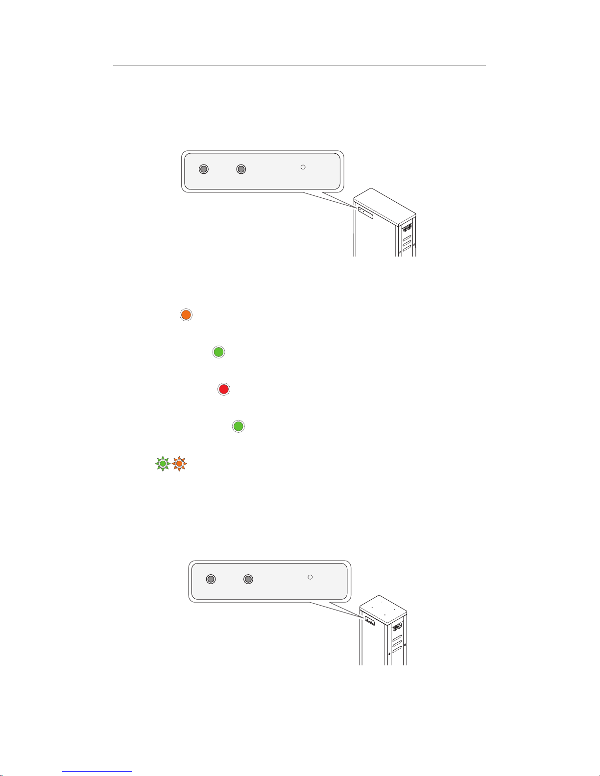
1.3 LED Indicators
Main battery pack
Sta
tus
Charge / Discharge
RESU 6.4
R
Status Charge / Discharge
RESU 6.4 EX
R
The LED indicators on the front of the main battery pack show its operational
state as follows:
Initializing : While the main pack is initializing itself, the Status indica-
tor is lit orange.
Normal operation : When the main pack is in normal operation, the Sta-
tus indicator is lit green.
Charge in progress : While the main pack is charging, the Charge / Dis-
charge indicator is lit red.
Discharge in progress : While the main pack is discharging, the Charge
/ Discharge indicator is lit green.
Alarm : When the main pack is in a warning or fault state, the Status
indicator alternately ashes green and orange. See Troubleshooting on
page 32.
Expansion battery pack
Status Charge / Discharge
RESU 6.4 EX
R
7

Introduction
The LED indicators on the front of the expansion battery pack show its oper-
ational state as follows:
Initializing : While the expansion pack is initializing itself, the Status in-
dicator is lit red.
Normal operation : When the expansion pack is in normal operation, the
Status indicator is lit green.
Standby : When the expansion pack is in the standby state, the Status
indicator ashes green. See Starting the Battery Pack on page 31.
Charge in progress : While the expansion pack is charging, the Charge /
Discharge indicator is lit red.
Discharge in progress : While the expansion pack is discharging, the
Charge / Discharge indicator is lit green.
Alarm : When the expansion pack is in a fault state, the Status in-
dicator alternately ashes green and red. See Troubleshooting on page
32.
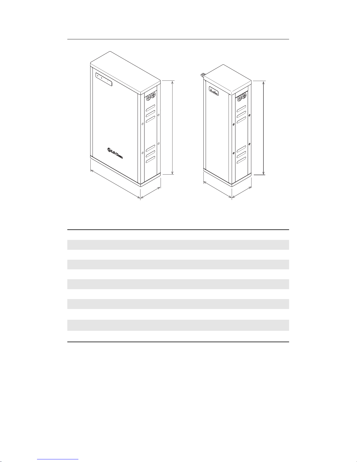
1.4 Specications
Main battery pack’s dimensions and weight
Length 406 mm
Width 165 mm
Height 664 mm
Weight 60 kg
Expansion battery pack’s dimensions and weight
Length 230 mm
Width 165 mm
Height 664 mm
Weight 32 kg
8
Introduction
Statu
s
Charge / Di
s
c
harge
RESU 6.4
R
664
165
406
165
230
664
Performance
Nominal voltage 51.8 V
Operating voltage 45.2 V to 58.1 V
Nominal capacity with no expansion pack 126 A·h
Nominal capacity with 1 expansion pack 189 A·h
Nominal capacity with 2 expansion packs 252 A·h
Nominal energy with no expansion pack 6.4 kW·h
Nominal energy with 1 expansion pack 9.6 kW·h
Nominal energy with 2 expansion packs 12.8 kW·h
Nominal charge current
1)
42 A
Nominal discharge current
2)
42 A
Maximum discharge current
3)
110 A
1)
in constant-current/constant-voltage charging mode
2)
in constant-current discharging mode
3)
If the temperature inside the battery pack rises, the charging and discharging current may
be derated to keep the battery safety and lifetime.
9

Introduction
Power cable requirements
Conductor cross-sectional area
1)
33 mm2to 50 mm
2
Cable outer diameter 12 mm to 18 mm
Cable lug hole size M8
Cable lug width 21 mm
Maximum cable length 5 m per cable
1)
The external resistance of the power cable between the battery pack and the inverter must be
below 10 mΩ.
If these requirements cannot be met, contact LG Chem or your distributor.
Environmental requirements
Available operating temperature
1)
0°C to 40°C
Optimal operating temperature 15°C to 30°C
Operating relative humidity 25% to 95%
Storage temperature −30°C to 50°C
Storage relative humidity 25% to 95%
1)
When the ambient temperature is below 10°C, charging and discharging current may be de-
rated to keep the battery safety and lifetime.
Communication interface
Protocol CAN 2.0B
Channel 1
Fuse for the expansion pack
Model PV14 63A gG
Length 51 mm
Diameter 14 mm
Rated current 63 A DC
Rated voltage 250 V DC
Standards IEC 60269, EN 60269
10

2 Safety
2.1 General Precautions for the Battery Pack
WARNING
Failure to observe the precautions described in this section can cause seri-
ous injury to persons or damage to property.
Observe the following precautions:
• Risks of explosion
– Do not subject the battery pack to strong impacts.
– Do not crush or puncture the battery pack.
– Do not dispose of the battery pack in a re.
• Risks of re
– Do not expose the battery pack to temperatures in excess of 50°C.
– Do not place the battery pack near a heat source such as a replace.
– Do not expose the battery pack to direct sunlight.
– Do not allow the battery connectors to touch conductive objects such as
wires.
• Risks of electric shock
– Do not disassemble the battery pack.
– Do not touch the battery pack with wet hands.
– Do not expose the battery pack to moisture or liquids.
– Keep the battery pack away from children and animals.
• Risks of damage to the battery pack
– Do not allow the battery pack to come in contact with liquids.
– Do not subject the battery pack to high pressures.
– Do not place any objects on top of the battery pack.
11
Safety
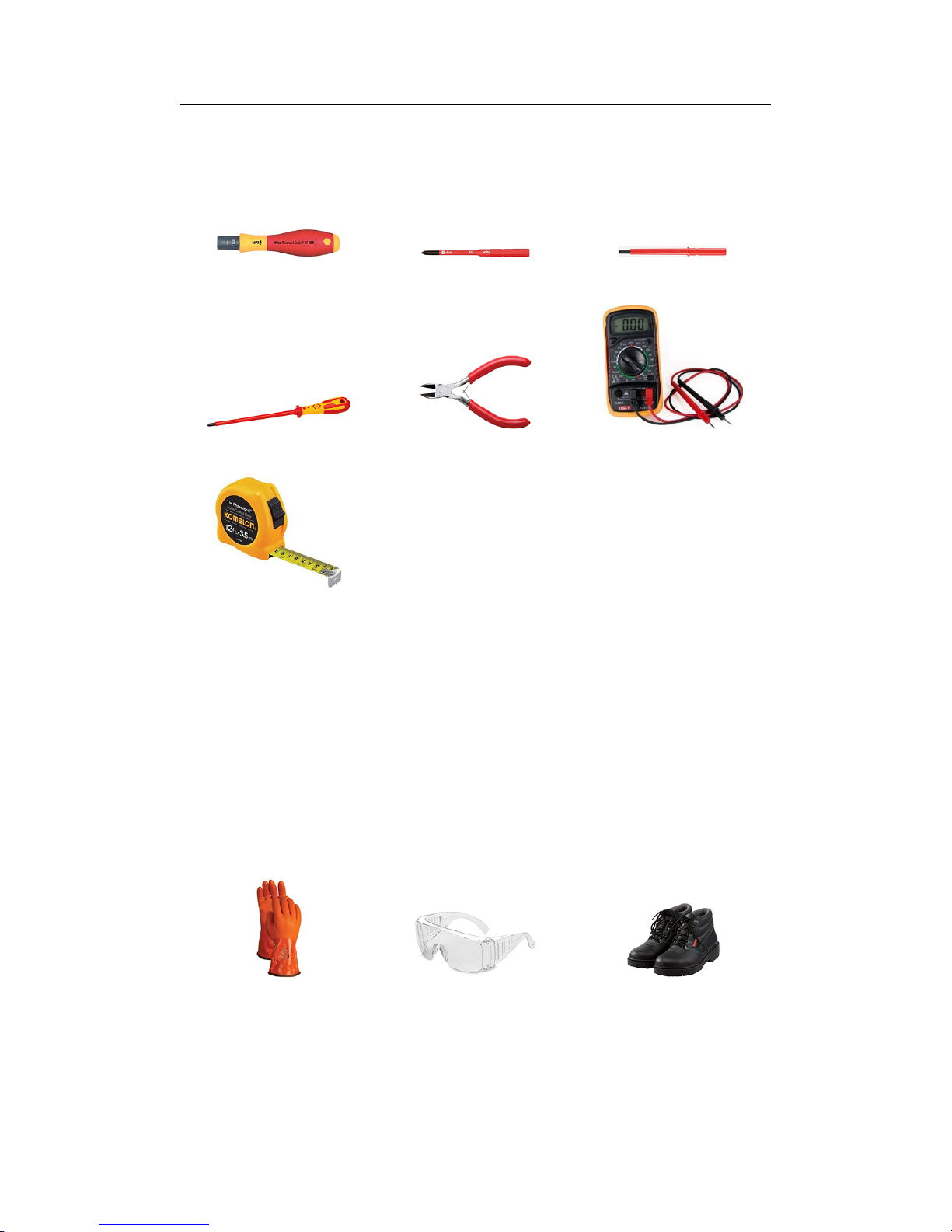
2.2 Tools
The following tools are required to install the battery pack:
Torque screwdriver Phillips-screwdriver bit Hex-key bit
Phillips-head screwdriver Wire cutter Voltmeter
Tape measure
Use properly insulated tools to prevent accidental electric shock or short cir-
cuits. It is highly recommended to use adjustable tools and measuring instru-
ments that are certied for precision and accuracy.
2.3 Safety Gear
It is recommended to wear the following safety gear when dealing with the
battery pack.
Insulated gloves Safety goggles Safety shoes
12
Safety
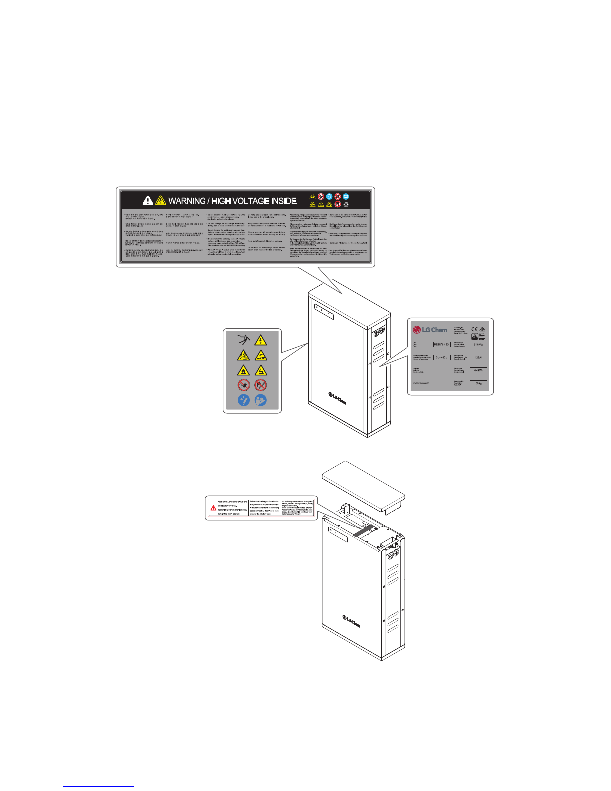
2.4 Warning Labels
Main battery pack
The nameplate is attached to the right side of the main battery pack, and warn-
ing labels are attached to the top and left side.
Status
C
harge / Discharge
RESU 6.4
R
*$1<14>&
Status
Charg
e /
Discharg
e
RE
SU 6.4
R
13
 Loading...