

Page 1
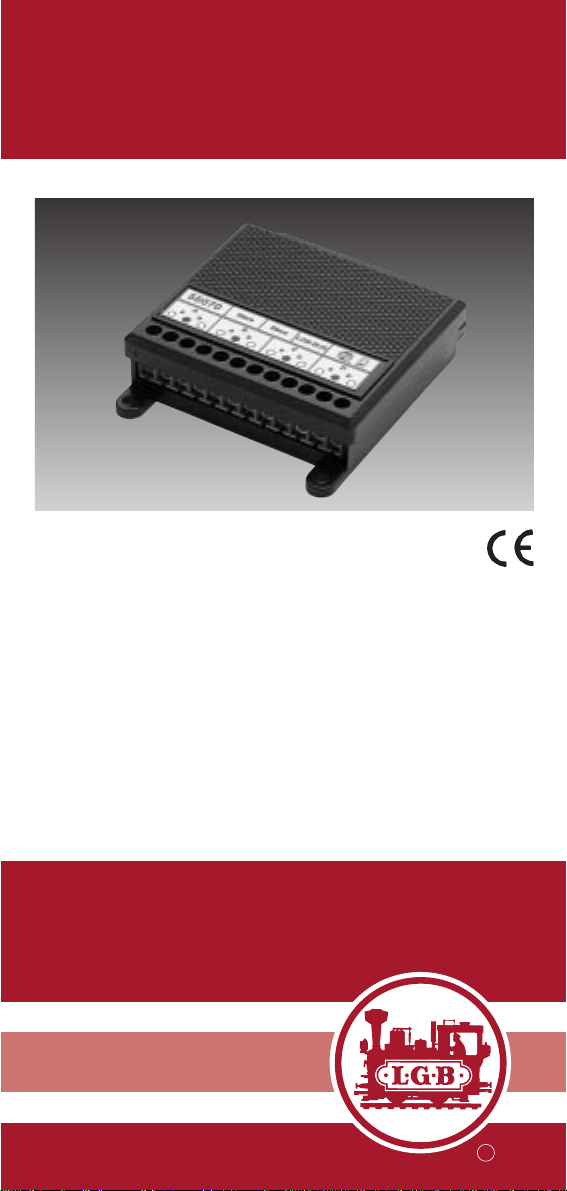
55070
MZS-Rückmeldemodul
DAS PRODUKT
Mit dem MZS-Rückmeldemodul
können Sie Ihre MZS-Weichendecoder 55025 automatisch stellen (z. B. über EPL-Gleiskontakte
17100). Weiterhin können Sie
über das Rückmeldemodul 55070
die Signale von EPL-Gleiskontakten 17100 und EPL-Zusatzschaltern 12030 und 12070 an Ihren
PC (mit Interface 55060) leiten
und so Ihre Anlage vollautomatisch steuern.
Jedes Rückmeldemodul wertet
die Signale von externen Kontakten (z. B. Gleiskontakten, Zusatzschaltern) aus. Bis zu 64 Rückmeldemodule können zusammen
eingesetzt werden.
BBeeddiieennuunnggssaannlleeiittuunngg
IInnssttrruuccttiioonn
IInnssttrruuccttiioonnss ddee SSeerrvviiccee
R
Page 2
Qualität
Permanente Materialkontrollen,
Fertigungskontrollen und die
Endkontrolle vor Auslieferung
garantieren unser gleichbleibend hohes Qualitätsniveau.
Wie bei einer wertvollen Uhr
werden feinstmechanische Präzisionsteile von Hand gefertigt.
Unsere Produkte sind Präzisionswertarbeit in Design und
Technik. Um wirklich ungetrübten Spaß zu haben, lesen Sie
bitte die Garantie- und Bedienungsanleitung.
Garantie
Wir garantieren 1 Jahr Fehlerfreiheit auf Material und Funktion. Berechtigte Beanstandungen innerhalb eines Jahres
nach Kaufdatum werden
kostenlos nachgebessert.
Das beanstandete Produkt,
zusammen mit dem Kaufbeleg,
Ihrem Händler übergeben oder,
ausreichend frankiert, an eine
der beiden untenstehenden
Serviceabteilungen einschicken:
ERNST PAUL LEHMANN
PATENTWERK
Service-Abteilung
Saganer Str.1-5
D-90475 Nürnberg
Tel: (0911) 83 707 0
LGB OF AMERICA
6444 Nancy Ridge Drive
San Diego, CA 92121
USA
Tel.: (858) 535-9387
Für Schäden durch unsachgemäße Behandlung oder
Fremdeingriff besteht kein
Garantieanspruch.
Transformatoren und Regler
unterliegen strengen CE-ULVorschriften und dürfen nur
vom Hersteller geöffnet und
repariert werden. Zuwiderhandlungen bewirken zwingend
Garantieverlust und generelle
Reparaturverweigerung.
Viel Freude am Spiel mit unserem gemeinsamen Hobby.
Qualité
Un système de contrôles constants des matériaux, de la production et des produits finis
garantit la qualité supérieure de
nos produits. A l’instar d’une
montre précieuse, tous les
composants de précision micromécaniques sont fabriqués à la
main.Nos produits se caractérisent par leur conception et finition de haute précision.
Afin d’obtenir la plus grande
satisfaction de ce produit, veuillez lire la garantie ainsi
que les instructions de service.
Garantie
Matériel et fonction sont entièrement garantis pour la période d’un an à partir de la date
d’achat. Toutes les réclamations justifiées faites au cours de
cette période, feront l’objet
d’une réparation gratuite.
Retourner le produit faisant
l’objet de la réclamation, avec
preuve de paiement, à votre
distributeur, ou le renvoyer - en
veillant à ce que l’affranchissement soit suffisant - à l’un des
services après-vente ci-dessous:
ERNST PAUL LEHMANN
PATENTWERK
Service-Abteilung
Saganer Str.1-5
D-90475 Nürnberg
ALLEMAGNE
Tel: (0911) 83 707 0
LGB OF AMERICA
Service Department
6444 Nancy Ridge Dr.
San Diego, CA 92121
USA
Tel: (858) 535-9387
La garantie est nulle et non
avenue en cas d’utilisation inadéquate ou d’intervention faite
par une personne non autorisée.
Les transformateurs et régulateurs sont conformes aux rigoureuses normes CE-UL et ne
peuvent être ouverts et réparés
que par le fabricant.T oute violation à cet égard entraînera la
perte impérative de tous les
droits de garantie et un refus de
toutes réparations quelles
qu’elles soient.
Nous vous souhaitons des heures d’amusement inoubliables
avec votre hobby qui est également le nôtre.
LIMITED WARRANTY
All of us at Ernst Paul Lehmann
Patentwerk are very proud of
this product. Ernst Paul Lehmann Patentwerk warrants it
against defects in material or
workmanship for one full year
from the date of original consumer purchase.
To receive warranty service,
please return this product,
along with the original purchase
receipt, to an authorized retailer
or to one of the LGB service
stations listed here:
Ernst Paul Lehmann
Patentwerk
Saganer Strasse 1-5
D-90475 Nürnberg
GERMANY
Telephone: (0911) 83 70 70
LGB of America
6444 Nancy Ridge Drive
San Diego, CA 92121
USA
Telephone: (858) 535-9387
This product will be repaired
without charge for parts or
labor. You are responsible for
any shipping costs, insurance
and customs fees.This warranty does not apply to products
that have been damaged after
purchase, misused or modified.
Transformers and controls are
subject to strict CE and UL
regulations and may only be
opened and repaired by the
manufacturer. This warranty
gives you specific legal rights,
and you may also have other
rights which vary from state to
state.
This warranty only applies to
products purchased from authorized retailers.To find an authorized retailer, contact one of
the LGB service stations listed
here.
R
ER
ER
TIFICA
TIFICA
C
C
T
T
Page 3
3 4
LGB-Bus
1
5
55110
LGB-Bus
55070
A
a
b
LGB-BusLGB-Bus
LGB-BusLGB-Bus
Slave LGB-BUS
Slave
C
B
aabb
51750
D
D
D
ba
55070
A
64
1
a
aBb
C
ab
D
D
b
a
LGB-BUS
SlavebSlave
1710012030 17100
55060
50110
LGB-Bus
PC
PC-RS232
D
55000
Gleis
1
Prog ABCDD IN Prog ADBINC D
55110
LGB-BusLGB-Bus LGB-Bus
D
LGB-BusLGB-Bus LGB-Bus
32
5502555025
55055
LGB-Bus
51070
6723
1 234
5678
#
9
0
F
50110
D
6723
1 234
5678
ID#
#
9
F
D
b2
a2
Kehrschleife/ Reversing Loop
55080
a1
Hauptgleis/ Main Track
55070
A
a
bBab
b1
Slave
Slave
1A
LGB-BUS
ab
2A
1B
2B
2A1A
D
DC
b
a
2B 1B
164
Slave
55070
A
a
b
aBb
LGB-BUS
Slave
C
ab
D
D
ba
12030 17100 17100
0
51750
Page 4

5
Abb. 2: Programmieren: Stellen von Weichendecodern 55025
Fig. 2: Programming: Controlling 55025 Switch Decoders
Fig. 2: Programmation: commande des décodeurs d ‘aiguillage
55025
- Kabel mit viereckigem Westernstecker abziehen. Deckel abnehmen.
- DIP-Schalter entsprechend der Tabelle einstellen.
- Kabel zum 55110 MZS-Adapter/Verteiler einstecken.LED blinkt schnell.
- Kabel wieder abziehen. DIP-Schalter auf OFF stellen.
- Kabel zum normalen Betrieb einstecken.
- Disconnect phone-style connector.Remove top of 55070.
- Set DIP switches as shown in table.
- Connect cable to 55110 MTS Remote Adapter.LED flashes rapidly.
- Disconnect cable.Set DIP switches to OFF.
- Reconnect cables for normal operation.
- Enlever les connecteurs de type téléphone.Déposer la par tie supér ieure de l’interface.
- Placer les commutateurs des commutateurs à positions multiples à la
position indiquée sur le tableau.
- Brancher le câble sur l’adapteur SMT 55110, la DEL clignote rapidement.
- Débrancher le câble puis placer les commutateurs des commutateurs à
positions multiples sur OFF.
- Rebrancher les câbles en configuration d’utilisation normale de l’accessoire.
Funktion Adressbereich DIP-Schalter ON
Function Address area DIP switch ON
Fonction Bloc d’adresses Commutateurs sur ON
55025 1-4 8
55025 5-8 8 + 1
55025 9-12 8 + 2
55025 13-16 8 + 2 + 1
55025 17-20 8 + 3
55025 21-24 8 + 3 + 1
55025 25-28 8 + 3 + 2
55025 29-32 8 + 3 + 2 + 1
55025 33-36 8 + 4
55025 37-40 8 + 4 + 1
55025 41-44 8 + 4 + 2
55025 45-48 8 + 4 + 2 + 1
55025 49-52 8 + 4 + 3
55025 53-56 8 + 4 + 3 + 1
55025 57-60 8 + 4 + 3 + 2
55025 61-64 8 + 4 + 3 + 2 + 1
55025 65-68 8 + 5
55025 69-72 8 + 5 + 1
55025 73-76 8 + 5 + 2
55025 77-80 8 + 5 + 2 + 1
55025 81-84 8 + 5 + 3
55025 85-88 8 + 5 + 3 + 1
55025 89-92 8 + 5 + 3 + 2
55025 93-96 8 + 5 + 3 + 2 + 1
55025 97-100 8 + 5 + 4
55025 101-104 8 + 5 + 4 + 1
55025 105-108 8 + 5 + 4 + 2
55025 109-112 8 + 5 + 4 + 2 + 1
55025 113-116 8 + 5 + 4 + 3
55025 117-120 8 + 5 + 4 + 3 + 1
55025 121-124 8 + 5 + 4 + 3 + 2
55025 125-128 8 + 5 + 4 + 3 + 2 + 1
2
Page 5

6
Abb.3: Programmieren des Rückmeldemoduls 55070 (Kontakte für Computer-Interface 55060)
Fig. 3: Programming 55070 MTS Feedback Interface (contacts for 55060
MTS Computer Interface)
Figure 3: Programmation de la multi-interface SMT 55070 (pour la commande de l’interface ordinateur SMT 55060)
- Programmiervorgang siehe Abb.2
- For programming sequence, see Fig.2.
- La séquence de programmation est détaillée à la figure 2.
Funktion Adressbereich DIP-Schalter ON
Function Address area DIP switch ON
Fonction Bloc d’adresses Commutateurs sur ON
Kontakt/Contact 129-132 8 + 6
Kontakt/Contact 133-136 8 + 6 + 1
Kontakt/Contact 137-140 8 + 6 + 2
Kontakt/Contact 141-144 8 + 6 + 2 + 1
Kontakt/Contact 145-148 8 + 6 + 3
Kontakt/Contact 149-152 8 + 6 + 3 + 1
Kontakt/Contact 153-156 8 + 6 + 3 + 2
Kontakt/Contact 157-160 8 + 6 + 3 + 2 + 1
Kontakt/Contact 161-164 8 + 6 + 4
Kontakt/Contact 165-168 8 + 6 + 4 + 1
Kontakt/Contact 169-172 8 + 6 + 4 + 2
Kontakt/Contact 173-176 8 + 6 + 4 + 2 + 1
Kontakt/Contact 177-180 8 + 6 + 4 + 3
Kontakt/Contact 181-184 8 + 6 + 4 + 3 + 1
Kontakt/Contact 185-188 8 + 6 + 4 + 3 + 2
Kontakt/Contact 189-192 8 + 6 + 4 + 3 + 2 + 1
Kontakt/Contact 193-196 8 + 6 + 5
Kontakt/Contact 197-200 8 + 6 + 5 + 1
Kontakt/Contact 201-204 8 + 6 + 5 + 2
Kontakt/Contact 205-208 8 + 6 + 5 + 2 + 1
Kontakt/Contact 209-212 8 + 6 + 5 + 3
Kontakt/Contact 213-216 8 + 6 + 5 + 3 + 1
Kontakt/Contact 217-220 8 + 6 + 5 + 3 + 2
Kontakt/Contact 221-224 8 + 6 + 5 + 3 + 2 + 1
Kontakt/Contact 225-228 8 + 6 + 5 + 4
Kontakt/Contact 229-232 8 + 6 + 5 + 4 + 1
Kontakt/Contact 233-236 8 + 6 + 5 + 4 + 2
Kontakt/Contact 237-240 8 + 6 + 5 + 4 + 2 + 1
Kontakt/Contact 241-244 8 + 6 + 5 + 4 + 3
Kontakt/Contact 245-248 8 + 6 + 5 + 4 + 3 + 1
Kontakt/Contact 249-252 8 + 6 + 5 + 4 + 3 + 2
Kontakt/Contact 253-256 8 + 6 + 5 + 4 + 3 + 2 + 1
Abb. 4: Programmieren des Rückmeldemoduls 55070 (ID-Nr.)
Fig. 4: Programming the Feedback Interface 55070 (ID No.)
Figure 4: Programmation du N° ID de la multi-interface SMT 55070
- Programmiervorgang siehe Abb.2
- For instructions on programming, see Fig.2
- La séquence de programmation est détaillée à la figure 2.
ID-Nr. DIP-Schalter ON
ID No. DIP switch ON
N° ID Commutateurs sur ON
1 8 + 7 + 1
2 8 + 7 + 2
3 8 + 7 + 2 + 1
4 8 + 7 + 3
5 8 + 7 + 3 + 1
6 8 + 7 + 3 + 2
7 8 + 7 + 3 + 2 + 1
4
3
Page 6

Achtung! Dieses Produkt darf
nur auf Anlagen verwendet werden, die mit dem LGB-Mehrzugsytem betrieben werden.
Vorsicht! Dieses Produkt ist nicht
wetterfest. Schützen Sie es vor
Feuchtigkeit.
Packungsinhalt
1. Rückmeldemodul
2. Kabel mit Westernsteckern
DAS LGB-PROGRAMM
Zum Einsatz mit diesem Produkt
schlagen wir folgende LGB-Artikel vor:
- 12030 EPL-Zusatzschalter
- 12070 EPL-Zusatzschalter, Typ 2
- 17100 EPL-Gleiskontakt
- 55025 MZS-Weichendecoder
- 55060 MZS-Interface mit PCSoftware
- 55110 MZS-Adapter/Verteiler
Informationen über das komplette
LGB-Programm finden Sie im
LGB-Katalog.
EINBAU
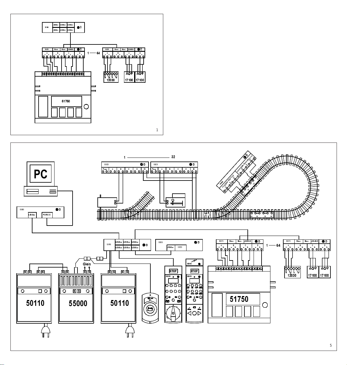
1.Am Rückmeldemodul finden
Sie eine zwölfpolige
Anschlußleiste (Abb. 1), die in
vier Gruppen (A - D) mit je drei
Anschlüssen (a, Masse, b)
unterteilt ist:
- Verbinden Sie den schwarzen
Anschluss in der Mitte der jeweiligen Gruppe mit einem Pol des
Kontaktes.
- An den weißen Eingängen a
oder b schließen Sie den anderen Pol des Kontaktes an.
Sie können an den Ausgängen a
und b zwei verschiedene Kontakte anschließen, z.B.um eine Weiche mit einem Kontakt auf
“abzweigen” und mit dem zweiten
Kontakt oder Taster wieder auf
“geradeaus” zu stellen.
Achtung! Die angeschlossenen
Kontakte oder Schalter dürfen
keine Fremdspannung führen.
Hinweise:
- Alle Massen der Rückmeldemodule sind im System miteinander verbunden.
- Bei EPL-Gleiskontakten 17100
und 17000 verbinden Sie die mit
Dreiecken gekennzeichneten
Anschlüsse miteinander.
- An jeden Anschluß können auch
mehrere Kontakte parallel angeschlossen werden.
- Um das Rückmeldemodul mit
dem Stellpult 51750 auszulösen, verbinden Sie den weißen
Anschluß am Stellpult 51750 mit
dem schwarzen Anschluß am
Rückmeldemodul, und den gelben und/oder grünen Anschluß
am 51750 mit jeweils einem der
weißen Anschlüsse a und b am
55070.
Achtung! Das Stellpult 51750
darf nicht separat mit Spannung
versorgt werden.
2.Auf der anderen Seite des
Rückmeldemoduls finden Sie
drei Buchsen für Westernstecker (Abb. 1).
- Verbinden Sie die linke, mit
“LGB-BUS” gekennzeichnete
Buchse über das beiliegende
LGB-Bus-Kabel mit der Zentrale
des LGB-Mehrzugsystems.
(Das so angeschlossene Modul
ist das Mastermodul.)
Achtung! Verwenden Sie nur das
beiliegende Kabel zum Anschluß
des Rückmeldemoduls.
Hinweis: Um das Rückmeldemodul an die MZS-Zentrale der
ersten Generation anzuschließen, benötigen Sie den MZSAdapter/Verteiler 55110.
Schließen Sie das Rückmeldemodul an den MZS-Adapter/Verteiler 55110 an.
- An den beiden rechten, mit
“Slave”gekennzeichneten Buchsen können Sie weitere MZSRückmeldemodule anschließen.
Weitere Rückmeldemodule (bis
zu 64) werden in Reihe (Slave
zu Slave) verbunden.
Vorsicht! Schließen Sie die
Westernstecker der MZS-Bausteine nicht an das Telefon-Netz
an. Die MZS-Bausteine würden
sofort zerstört.
3.Jeder Anschluß wertet das
Schließen eines Kontaktes
aus.Dies kann ein Momentkontakt oder ein Ein/Aus-Schalter
sein.Das Öffnen des Kontaktes
bewirkt keine Funktion.
Anwendungsbeispiele:
1. Stellen von MZS-Weichende-
codern 55025 über Gleiskontakte 17100, über EPL-Zusatzschalter 12030 oder über Stell-
7
Page 7

und Schaltpulte (z. B. 51750).
2. Rückmeldung an den PC bei
Steuerung über Interface
55060.
Hinweis: Der Arbeitsspeicher
des Rückmeldemoduls kann bis
zu 24 Kontaktauslösungen aufnehmen. Bis zu 5 Kontaktauslösungen pro Sekunde werden
abgearbeitet. Gehen mehr als 24
Daten im Arbeitsspeicher ein, so
werden diese verworfen und nicht
ausgewertet.
Programmieren
des Rückmeldemoduls
Jedes Rückmeldemodul erhält
vier aufeinander folgende Adressen, die in einem Adressraum (14, 5-8, 9-12 usw .) liegen (Ab b.2) ähnlich wie beim MZS-Weichendecoder. Entsprechend werden
jeweils die zugehörigen MZSWeichendecoder gestellt.
- Wenn Sie z. B. das Rückmelde-
modul auf den Adressraum 6164 programmieren, wird über
Ausgang A Weiche 61, über
Ausgang B Weiche 62, über
Ausgang C Weiche 63 und über
Ausgang D Weiche 64 gestellt.
- Bei Verwendung zur Rückmel-
dung über PC-Interface 55060
werden die Kontakte entsprechend der Tabelle (Abb. 3) von
129 bis 256 bezeichnet. Beispielsweise entspricht der
Adressraum 129 - 132 den Kontakten 129 a, 129 b (entsprechend der Ausgänge) bis 132 a,
132 b.
So programmieren Sie das
MZS-Rückmeldemodul 55070:
1. Kabel mit viereckigem Westernanschluß zum MZS-Adapter/Verteiler 55110 oder zur
MZS-Zentrale herausziehen.
2.Die vier Schrauben auf der
Unterseite des Gehäuses herausdrehen. Gehäuse öffnen
und DIP-Schalter nach beiliegender Tabelle (Abb.3) auf den
gewünschten Code stellen.
- Kabel von Zentrale oder MZS-
Adapter/Verteiler 55110 in die
LGB-BUS-Buchse einstecken.
- Bei schnell blinkender LED
wurde die Programmierung
erfolgreich abgeschlossen.
3. Kabel wieder abziehen.
4. Alle DIP-Schalter auf OFF stellen, Gehäuse schließen.
5. Kabel zum normalen Betrieb
einstecken.
Hinweis: Die Geräte-ID ist ab
Werk auf ID 2 gestellt und sollte
normalerweise nicht geändert
werden (Abb. 4). Die Geräte-ID
wird nur beim “Master”-Modul eingestellt.
Technische Daten
(für Experten)
- Nach Kontaktauslösung ist der
entsprechende Eingang ca. 2
Sekunden lang gesperrt. Das
verhindert Mehrfachauslösungen von Gleiskontakten durch
langsam fahrende Loks sowie
Kontaktprellen von Schaltern.
- Bei erkanntem Notaus werden
die Daten im Speicher des
jeweiligen Rückmeldemoduls
abgelegt und nach Aufheben
des Nothalts ausgegeben.
Stromversorgung
Achtung!
Um Sicherheit und
Zuverlässigkeit zu gewährleisten,
betreiben Sie das Produkt nur mit
LGB-Trafos und Fahrreglern. Bei
Verwendung von anderen Trafos
wird Ihre Garantie ungültig.
Weitere Informationen über die
LGB-Trafos und Fahrregler zur
Verwendung im Haus oder im
Freien und über das Mehrzugsystem finden Sie im LGB-Katalog.
AUTORISIERTER SERVICE
Bei unsachgemäßer Wartung
wird Ihre Garantie ungültig. Um
fachgerechte Reparaturleistungen zu erhalten, wenden Sie sich
an Ihren Fachhändler oder an die
LGB-Service-Abteilung:
Ernst Paul Lehmann Patentwerk
Service-Abteilung
Saganer Straße 1-5
D-90475 Nürnberg
DEUTSCHLAND
Tel.: (0911) 83707 0
Telefax: (0911) 8370770
Die Einsendung erfolgt zu Ihren
Lasten.
Hinweis: Informationen zu autorisierten LGB-Werkstätten in aller
Welt finden Sie im Internet unter
www.lgb.de.
VORSICHT! Dieses Produkt ist
nicht für Kinder unter 8 Jahren
geeignet. Bewahren Sie Verpackung und Bedienungsanlei-
8
Page 8
tung auf.
LGB, LEHMANN und der LEH-
MANN TOYTRAIN-Schriftzug
sind eingetragene Warenzeichen
der Firma Ernst Paul Lehmann
Patentwerk, Nürnberg, Deutschland. Andere Warenzeichen sind
ebenfalls geschützt.Produkte und
technische Daten können sich
ohne Vorankündigung ändern. ©
2000 Ernst Paul Lehmann Patentwerk.
55070
MTS Feedback Interface
THE PRODUCT
You can use the MTS Feedback
Interface for automatic control of
55025 MTS Switch Decoders.
Also, you can use the MTS Feedback Interface with the 55060
MTS Computer Interface for fully
automated train control.
In each case, the MTS Feedback
Interface receives signals (“feedback”) from external contacts, like
17100 EPL Track Contacts,
12030 and 12070 EPL Supplementary Switches or ordinary
electrical switches. The MTS
Feedback Interface then sends
signals to a MTS Switch Decoder
or MTS Computer Interface.
You can use up to 64 MTS Feedback Interfaces together on your
layout.
Attention! Use this product only
with the LGB Multi-Train System.
Caution! This product is not weather-resistant.Protect this product
from moisture.
This package contains:
1. Feedback interface
2.Cable with phone-style connec-
tors
THE PROGRAM
With this product, we recommend
the following items:
- 12030 EPL Supplementary
Switch
- 12070 EPL Supplementary
Switch, Type 2
- 17100 EPL Track Contact
- 55025 MTS Switch Decoder
- 55060 MTS Computer Interface
- 55110 MTS Remote Adapter
For information on the complete
LGB program, see the LGB catalog.
INSTALLATION
1.On the feedback interface,
there is a twelve-pole connector (Fig. 1) with four groups (A D) of three terminals each (a,
9
GB
USA
Page 9

ground, b):
- Connect the black terminal in
the center of the group with one
pole of the contact.
- Connect the white terminal, a or
b, with the second pole of the
contact.
You can connect two separate
contacts to the terminals a and b,
e. g., to set a track switch to
“straight” with one contact and to
“diverging” with another contact.
Attention! The switches and
contacts you connect to the MTS
Feedback Interface must not
carry any voltage.
Hints:
- All black “ground” terminals of
the feedback interfaces are
connected.
- When using EPL Track Contacts
17100 and 17000, connect both
terminals marked with triangles
among each other.
- You can connect several contacts to each terminal on the
55070. They must be wired in
parallel.
- When using the EPL Control
Box 51750 to trigger the MTS
Feedback Interface, connect the
white terminal on the 51750 to
the black terminal on the 55070,
and the yellow and green terminals on the 51750 each to one
of the white terminals on the
55070.
Attention! Do not connect the
EPL Control Box 51750 to a
transformer.
2. On the other side of the feedb-
ack interface, there are three
phone-style sockets (Fig.1).
- Connect the left socket marked
“LGB-BUS” with the MTS Central Station using the included
cable. (The first interface
connected to the Central Station
is the “Master.”)
Attention! Use only the included
cable to connect the MTS Feedback Interface.
Hint: To connect the MTS Feedback Interface 55070 to the original
MTS Central Station, you need
the 55110 MTS Remote Adapter.
Connect the 55070 to the 55110.
- Use the two sockets on the right
marked “Slave”to connect additional MTS Feedback Interfaces .
Up to 64 additional Feedback
Interfaces are connected in
series (slave to slave).
Caution! Do not connect the
phone-style connectors of MTS
products to your phone system.
The MTS product will be destroyed!
3. Each terminal triggers if the
connected contact is closed.
The contact can be a momentary switch or an On/Off switch.
Opening the contact does not
trigger a function.
Examples:
1. Set your 55025 MTS Switch
Decoders using 17100 Track
Contacts, 12030 EPL Supplementary Switches or EPL Control Boxes (e.g., 51750).
2.Feedback to your PC with
55060 MTS Computer Interface.
Hint: The memory of the MTS
Feedback Interface can save up
to 24 signals (contact triggerings).
Up to 5 signals per second are
sent to the MTS Central Station.If
more than 24 signals accumulate
in the memory, the additional signals are lost.
Programming the
MTS Feedback Interface
Each MTS Feedback Interface is
assigned an address block of four
consecutive addresses -- for
example, 1-4, 5-8, 9-12, etc. (Fig.
2) -- similar to the addresses of
55025 MTS Switch Decoders.
The MTS Feedback Interface triggers the 55025 MTS Switch
Decoders with corresponding
addresses.
- Example: You program the MTS
Feedback Interface to address
block 61-64. Now terminal A
controls track switch 61, terminal B controls track switch 62,
terminal C controls track switch
63, and terminal D controls track
switch 64.
- If you are using the 55060 MTS
Computer Interface, the contacts are numbered from 129 to
256 (Fig.3).Thus, address block
129 - 132 corresponds to
contacts 129 a, 129 b (for terminals a and b) to 132 a, 132 b.
To program the 55070
MTS Feedback Interface:
1. Disconnect the cable (phonestyle connector) to the 55110
10
Page 10

11
MTS Remote Adapter or MTS
Central Station.
2. Remove the four screws on the
bottom of the housing. Open
the housing and select the
address block according to the
code in the table (Fig. 3).
- Connect the cables from the
MTS Central Station or the
55110 MTS Remote Adapter.
- Once the LED is flashing rapidly,
the programming is complete.
3. Remove the cables.
4. Set all DIP switches to OFF.
Close the housing of the feedback interface.
5. Connect the cables for normal
operation.
Hint: The device ID is pre-set at
the factory to ID 2 (Fig. 4). Under
most circumstances, the device
ID should not be changed. The
device ID is set only on the
“master” feedback interface.
Specifications
for advanced users
- After a contact is triggered, the
corresponding terminal is
blocked for approximately 2
seconds. This prevents multiple
triggering due to slow locos
crossing track contacts or
“bouncing” of switches.
- Once an emergency stop has
been recognized by the system,
all data is saved by each feedback interface and released after
a restart.
Power Supply
Attention! For safety and reliabi-
lity, operate this product with LGB
power supplies (transformers,
power packs and controls) only.
The use of non-LGB power supplies will void your warranty.
For more information on LGB
power supplies for indoor , outdoor
and multi-train operation, see the
LGB catalog.
AUTHORIZED SERVICE
Improper service will void your
warranty. For quality service,
contact your authorized retailer or
one of the following LGB factory
service stations:
Ernst Paul Lehmann Patentwerk
Reparatur-Abteilung
Saganer Strasse 1-5
D-90475 Nürnberg
GERMANY
Telephone: (0911) 83707 0
Fax:(0911) 83707 70
LGB of America
Repair Department
6444 Nancy Ridge Drive
San Diego, CA 92121
USA
Telephone: (858) 535-9387
Fax:(858) 535-1091
You are responsible for any shipping costs, insurance and
customs fees.
Hint: Information on LGB repair
centers around the world is available online at www.lgb.de.
CAUTION! This product is not for
children under 8 years of age.
Save the supplied packaging and
instructions.
LGB, LEHMANN and the LEHMANN TOYTRAIN logotype are
registered trademarks of Ernst
Paul Lehmann Patentwerk, Nürnberg, Germany. Other trademarks
are the property of their owners.
Products and specifications are
subject to change without notice.
© 2000 Ernst Paul Lehmann Patentwerk.
Page 11

55070
Multi-interface SMT
LE PRODUIT
La multi-interface SMT peut être
utilisée pour la commande automatique des décodeurs d’aiguillage SMT 55025. Elle peut également être utilisée avec l’interface
ordinateur 55060 pour une commande du réseau entièrement
automatisée.
Dans chaque cas, la multi-interface SMT reçoit des signaux (rétroaction) de contacts externes
comme les contacts de voies EPL
17100, les interrupteurs supplémentaires EPL 12030 et 12070,
ou des interrupteurs ordinaires.
La multi-interface SMT envoie
alors des signaux vers un décodeur d’aiguillage SMT ou une
interface d’ordinateur SMT.
Vous pouvez utiliser jusqu’à 64
multi-interfaces SMT sur votre
réseau.
Attention ! Utiliser cet accessoire uniquement avec le système
SMT de LGB.
Mise en garde ! Ce produit ne
résiste pas aux intempéries.
Protéger le produit de l’humidité.
La boîte renferme :
1.La multi-interface
2.Un câble avec des connecteurs
de type téléphone
LE PROGRAMME
Nous recommandons d’utiliser les
accessoires suivants avec ce produit :
- 12030 Interrupteur supplémen-
taire EPL
- 12070 Interrupteur supplémen-
taire EPL, type 2
- 17100 Contact de voies EPL
- 55025 Décodeur d’aiguillage
SMT
- 55060 Interface ordinateur SMT
- 55110 Adapteur SMT
Se reporter au catalogue général
LGB pour des renseignements
sur le programme LGB complet.
INSTALLATION
1.La multi-interface SMT est
équipée d’un connecteur à
douze broches (fig 1) réparties
en quatre groupes (A – D) de
trois broches (a, masse, b) :
Raccorder la broche noire située
- au centre du groupe
- à un pôle du contact.
Raccorder la broche blanche, a
ou b, au deuxième pôle du
contact.
Vous pouvez raccorder deux
contacts séparés aux broches a
et b, par exemple, pour indiquer à
un interrupteur de diriger le trafic
«droit devant» avec un contact et
«déviation» avec un autre
contact.
Attention ! Les interrupteurs et
contacts raccordés à la multiinterface SMT ne doivent porter
aucune tension.
Conseils :
- Toutes les broches noires de
«mise à la masse» des multiinterfaces sont raccordées.
- Lors de l’utilisation des contacts
de voies EPL 17100 et 17000,
raccorder les deux broches avec
triangle entre elles.
- Il est possible de raccorder plusieurs contacts à chaque broche
du 55070, ils doivent être câblés
en parallèle.
- Si le boîtier de commande EPL
51750 est utilisé pour déclencher la multi-interface SMT, raccorder la broche blanche du
51750 à la broche noire du
55070, ainsi que les broches
jaune et verte du 51750, chaque
broche à l’une des broches
blanches du 55070.
Attention ! Ne pas raccorder le
boîtier de commande EPL 51750
à un transformateur.
2.Trois prises femelles de type
téléphone sont situées de l’autre côté de la multi-interface (fig
1).
- Raccorder la prise gauche
identifiée «LGB-BUS » au
poste central SMT au moyen du
câble fourni. (La première interface raccordée au poste central
est l’interface «maîtresse»).
Attention ! Utiliser uniquement
le câble fourni pour raccorder la
multi-interface SMT
Conseil : Il est nécessaire d’utiliser l’adapteur SMT 55110 pour
raccorder la multi-interface SMT
F
Page 12

55070 au poste central SMT original. Raccorder la 55070 au
55110.
- Utiliser les deux prises femelles
de droite identifiées «Slave»
pour raccorder des multi-interfaces supplémentaires.On peut
raccorder en série un maximum
de 64 multi-interfaces supplémentaires (esclave à esclave).
Mise en garde ! Ne pas raccorder les fiches de types téléphone
des produits SMT à votre installation téléphonique sous peine de
destruction du produit SMT !
3. Chaque broche déclenche lor-
sque le contact raccordé se
ferme. Le contact peut être de
type interrupteur à action
momentanée ou interrupteur
marche/arrêt. L’ouverture du
contact n’active pas une fonction.
Exemples :
1. Mettez vos décodeurs d’aiguil-
lage SMT 55025 en place en
utilisant des contacts de voies
17100, des interrupteurs supplémentaires EPL 12030 ou
des boîtiers de commande
EPL (par exemple, 51750).
2. Assurez le retour d’information
vers l’ordinateur par l’interface
ordinateur SMT 55060.
Conseil : La mémoire de la
multi-interface SMT a une capacité maximale de 24 signaux
(déclenchements de contacts). 5
signaux par seconde maximum
sont envoyés v ers le poste centr al
SMT. Les signaux qui arrivent lorsque la mémoire est saturée (24
signaux) sont perdus.
Programmation
de la multi-interface SMT
Chaque multi-interface SMT possède un bloc de quatre adresses
consécutives, par exemple, 1-4,
5-8, 9-12, etc.(fig 2) – semblables
aux adresses du décodeur d’aiguillage SMT 55025. La multiinterface déclenche les décodeurs d’aiguillages SMT 55025
avec l’adresse correspondante.
-Exemple : Vous programmez la
multi-interface avec le bloc d’adresses 61-64. La bor ne A commande l’interrupteur 61, la borne
B commande l’interrupteur 62, la
borne C commande l’interrupteur
63 et la borne D commande l’in-
terrupteur 64.
- Si vous utilisez l’interface ordinateur SMT 55060, les contacts sont numérotés de 129 à 256
(fig 3). Le bloc d’adresses 129132 correspond aux contacts
129 a, 129 b, (pour les bornes
a et b) à 132 a, 132 b.
Pour programmer
la multi-interface SMT 55070 :
1. Débrancher le câble (connec-
teur de type téléphone) de l’adapteur SMT 55110 ou du poste
central SMT.
2. Enlever les quatre vis situées à
la partie inférieure du boîtier.
Ouvrir le boîtier et sélectionner
le bloc d’adresses en fonction
du code du tableau (fig 3).
- Raccorder les câbles du poste
central SMT ou de l’adapteur
55110.
- La programmation est terminée
lorsque la DEL clignote rapidement.
- Débrancher les câbles.
- Placer tous les commutateurs à
positions multiples sur OFF.
Refermer le boîtier de la multiinterface.
- Rebrancher les câbles en confi-
guration de fonctionnement normal.
Conseil : L’identification de l’accessoire a été déterminée en
usine, elle s’appelle ID 2, cette
identification ne doit normalement
pas être modifiée (fig 4). Elle n’existe que sur la multi-interface
«maîtresse».
Spécifications
pour les utilisateurs experts
- Après déclenchement d’un
contact, la borne correspondante est bloquée pendant environ
2 secondes, ceci afin d’éviter
des déclenchements multiples
dans le cas de locomotives lentes passant sur les contacts de
voie ou le «rebondissement»
des interrupteurs.
- Dès que le système reconnaît
un arrêt d’urgence, chaque
multi-interface sauvegarde les
données et ces dernières sont
libérées après le redémarrage.
Blocs d’alimentation
Attention !
Pour des raisons de
sécurité et de fiabilité, toujours
utiliser les blocs d’alimentation
LGB (transformateurs, blocs d’ali-
Page 13

mentation, commandes) pour
faire fonctionner cette multi-interface. L’utilisation de blocs d’alimentation autres que les blocs
d’alimentation LGB rendra la
garantie nulle et non avenue. Se
reporter au catalogue général
LGB pour des renseignements
complémentaires au sujet des
blocs d’alimentation pour utilisation à l’intérieur, à l’extérieur et
pour les systèmes multitrains.
CENTRES D’ENTRETIEN
AUTORISÉS
Un manque d’entretien rendra la
garantie et non avenue. Pour un
service après-vente de qualité,
entrer en contact avec votre distributeur autorisé ou l’un des centres d’entretien ci—dessous :
Ernst Paul Lehmann Patentwerk
Service – Abteilung
Saganer Strasse 1-5
D-90475 Nuremberg
ALLEMAGNE
Téléphone (0911) 83707 0
Fax : (0911) 83770
LGB of America
Service des réparations
6444 Nancy Ridge Drive
San Diego CA 92121
États-Unis
Téléphone (858) 535-9387
Fax : (858) 535-1091
L’expéditeur est responsable des
frais d’expédition, de l’assurance
et des frais de douane.
Conseil : Pour des renseignements au sujet des centres d’entretien LGB dans le monde, consulter le site web à www.lgb.de.
ATTENTION ! Ce produit n’est
pas pour les enfants au-dessous
de 8 ans.Consulter l’emballage et
les instructions.
LGB, LEHMANN et le logo LEHMANN TOYTRAIN sont des marques déposées de Ernst Lehmann Patentwerk, Nuremberg,
Allemagne et sont la propriété de
leurs détenteurs. Les produits et
spécifications sont sujets à modifications sans préavis. © 2000
Ernst Paul Lehmann Patentwerk.
Page 14
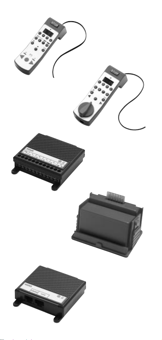
55015
55055
55016
55025
55050
Page 15
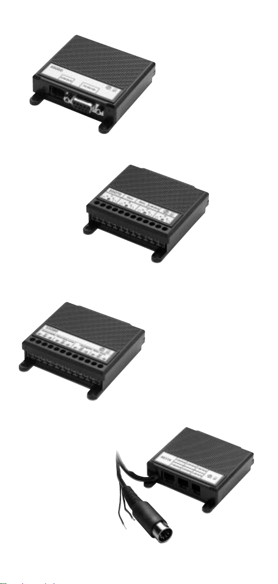
10
55110
55070
55060
55080
Page 16

8.869110.136 1.0 0200 PF
Änderungen der technischen Ausführungen vorbehalten.
We reserve the right to make technical alterations without prior notice.
Modifications de constructions réservées.
Für drinnen und draussen - For indoors and outdoors
Achtung!
Verpackung und Betriebsanleitung aufbewahren!
Nicht für Kinder unter 8 Jahren geeignet, modellbedingt besteht Quetsch- und
Klemmgefahr durch Antriebsgestänge der Lok.
Nicht für Kinder unter 8 Jahren geeignet, wegen funktions- und modellbedingter
scharfer Kanten und Spitzen.
Attention!
Save the supplied instructions and packaging!
This product is not for children under 8 years of age. It has moving parts that can
pinch and bind.
This product is not for children under 8 years of age.This product has small parts,
sharp parts and moving parts.
Attention!
Veuillez conserver l’emballage et le mode d’emploi!
Ne convient pas aux enfants de moins de 8 ans. L’embiellage de la locomotive peut
pincer les doigts de jeunes enfants.
Ne convient pas aux enfants de moins de 8 ans. Présence de petits éléments
susceptibles d’être avalés.
Attenzione!
Conservare l’imballo e le istruzioni per l’uso!
Non adatto a bambini di età inferiore agli 8 anni poiché vi è possibilità a pericolo di
schiacciamento delle dita quando il treno è in funzione.
Non adatto a bambini di età inferiore agli 8 anni in quanto le strutture presentano
spigoli vivi e punte accuminate.
Atención!
Guardar el carton de embalaje y las Instrucciones para el uso!
No adecuado para niños menores de 8 años. Según el modelo, existe el
peligro de sufrir contusiones o de cogerse los dedos a causa del varillaje de
accionamiento de la locomotora.
No adecuado para niños menores de 8 años, debido a cantos y puntas peligrosas
condicionadas por la función o el modelo.
Attentie!
Verpakking en gebruiksaanwijzing bewaren!
Niet geschikt voor kinderen onder de 8 jaar omdat deze loc aandrijfstangen bezit
waaraan kinderen zich kunnen bezeren.
Niet geschikt voor kinderen onder de 8 jaar omdat dit model funktionele scherpe
kanten en punten bezit.
EERRNNSSTT PPAAUULL LLEEHHMMAANNNN
PPAATTEENNTTWWEERRKK
Saganer Str. 1-5 · D-90475 Nürnberg
made
in
Germany
 Loading...