

LG WM2496M Training Manual

TRAINING MANUAL
WM2496 Washer Training
Spring 2007
Service
Digital Appliance

WM2496H*M
Contact Information cover
Safety Notices and Warnings 1
Contents 2
Introduction 4
Specifications 5
Features 6
Display and Controls 7
Warranty 8
Serial Number Identification 9
Fuzzy Logic 10
Door Lock 10
Door Locked Lamp 10
Water Circulation 11
Parts Identification (Callout) 12
Accessories 13
Remote Monitor and Modem 14
Installation 15
Pedestal 16
Connections 18
Water 18
Drain 18
Electrical 18
Program Chart 19
Before Performing Service 19
Dispenser 20
Test Mode 22
Check Water Level Frequency 22
Error Display (Error Codes) 23
Diagnosis and Check Lists 25
Door Error 25
Drain Error 25
Oversudsing 26
Laundry products Do Not Dispense 26
Other Errors 26
WM2496H*M Page 2 of 58 TRAINING MANUAL

Diagnosis and Troubleshooting 27
No Power 27
Noise and Vibration During Spin 28
SpinSense (to resolve vibration issues) 29
No Water Supply 30
Detergent Does Not Flow In 30
Bleach and Softener Do Not Flow In 31
Heater Operation Without Water 32
Abnormal Sound 32
Drain Malfunction 32
Wash Heater Malfunction (No Heating) 33
Heater Malfunction (Continuous Overheating) 33
No Water Circulation 34
Spin Malfunction 35
dE Error Code 35
Disassembly and Repair 36
Block Wiring Diagram 36
Top Plate 36
Control Panel 37
Main Board 38
Dispenser 39
Noise Filter 39
Front Cabinet Cover 40
Door 42
Door Switch Removal 42
Pumps (Drain and Circulation) 43
Heater 44
Thermistor 44
Removal of Objects Between Tub and Drum 45
Motor 46
Tub and Drum 48
Damper 49
Tips and Tricks 50
Hoses 50
Baffles (Roller Jets) 50
Mushroom Valve 50
Ball Sensor (Off Balance Sensor) 50
Wiring Diagram 51
Exploded Views 52
Parts List 55
070125
WM2496H*M Page 3 of 58 TRAINING MANUAL

INTRODUCTION
The WM2496 washer and dryer are very similar to the previous series, with the
exception of the re-shaped front panel and the convertible dryer control. The
WM2496 machines are specifically designed to be sold as a stacked product,
and the dryer is delivered with the control panel mounted at the bottom of the
dryer. This causes the washer and dryer control panels to be adjacent when the
products are installed and stacked. Of course, they can be installed in a standard,
side-by-side configuration with the dryer controls mounted at the top of the dryer.
WM2496H*M Page 4 of 58 TRAINING MANUAL
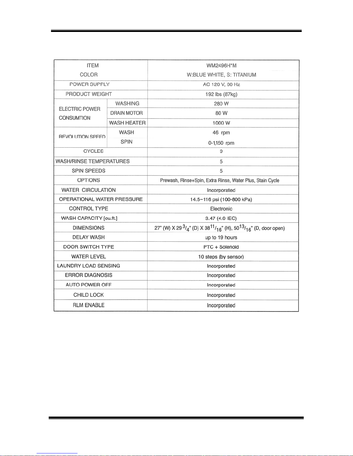
SPECIFICATIONS
WM2496H*M Page 5 of 58 TRAINING MANUAL
FEATURES
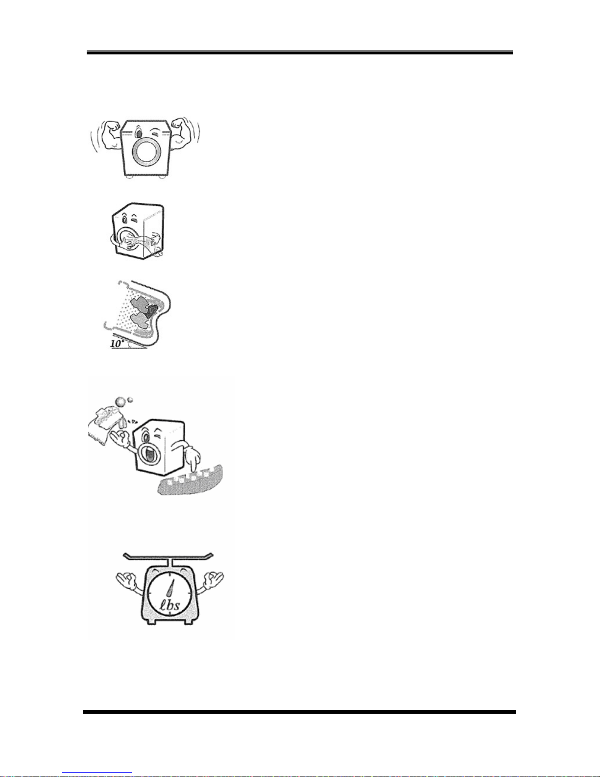
LARGE CAPACITY
The larger drum (4.0 cu. ft.) allows washing of
larger (heavier) loads and oversized items
(comforters, curtains, blankets, etc.) There is less
wrinkling and tangling of the laundry.
DIRECT DRIVE
The brushless DC motor drives the drum directly
without belts, pulleys, or transmissions. The
maximum spin speed of 1,150 RPM extracts more
water from the laundry, reducing drying times.
TILTED DRUM/LARGE DOOR
The tilted drum (10°) and large door opening allow
easier loading and unloading.
ROLLER JETS and BALLS
The baffles pick up water as the drum turns and
allow it to pour through the clothing as it tumbles.
The balls enhance the washing performance while
maintaining fabric care.
AUTOMATIC LOAD DETECTION
The microprocessor reads the current required to
turn the drum and determines the weight of the
load. This input is used to make numerous
decisions during the wash cycle.
WM2496H*M Page 6 of 58 TRAINING MANUAL
FEATURES, continued
DISPLAY and CONTROLS
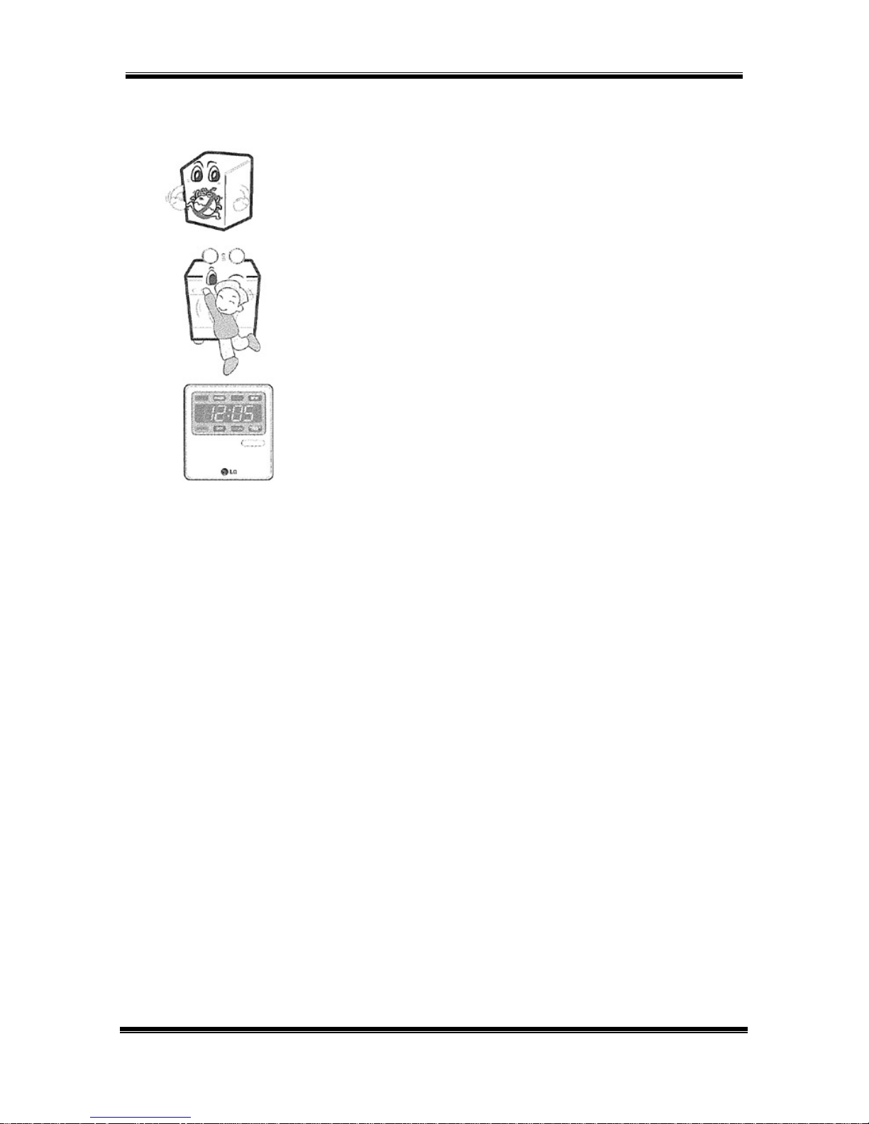
BUILT-IN HEATER
The internal heater helps maintain the water
temperature at its optimal temperature for
selected cycles. The SANITARY cycle kills most
common germs and bacteria.
CHILD LOCK
This allows the user to lock the controls. Children
then cannot play with the buttons and disturb the
wash cycle.
REMOTE LAUNDRY MONITOR
Available separately, the remote monitor displays
the cycle and remaining time on the washer and
dryer. It can be plugged in to any outlet in the
house.
The control panel is located on the front of the WM2496 Washer. All options are
available from the control panel.
Extra Hot 167° F
Hot 122° F
Warm 104° F
Cold 77° F
Press EXTRA HOT/COLD and EXTRA HIGH to read the drum RPM.
Press WARM/WARM and NORMAL to read the water temperature in ° Celsius.
Press WARM/COLD and LOW to read the water level frequency.
WM2496H*M Page 7 of 58 TRAINING MANUAL
Extra High 1,150
High 980
Normal 960
Low 600
SOIL LEVEL
adds time to
wash and
spin cycles
STAIN CYCLE
adds time and
changes
temperature
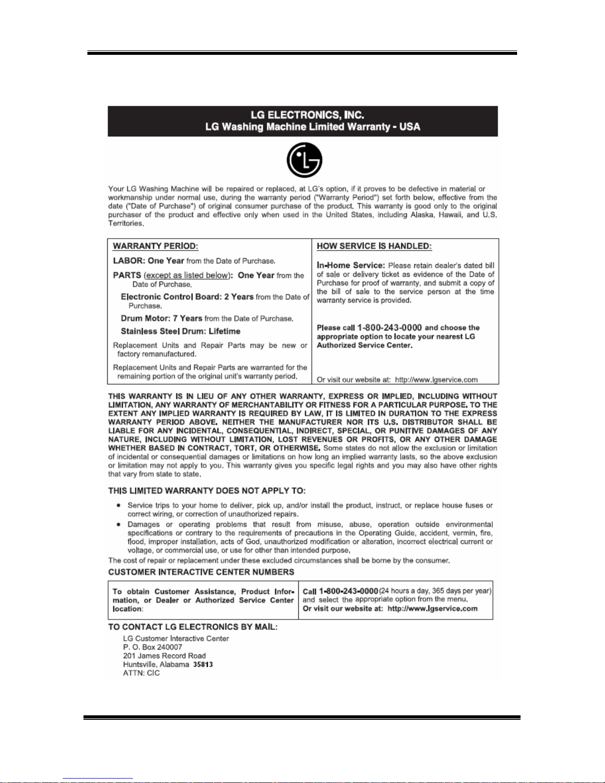
WARRANTY
WM2496H*M Page 8 of 58 TRAINING MANUAL
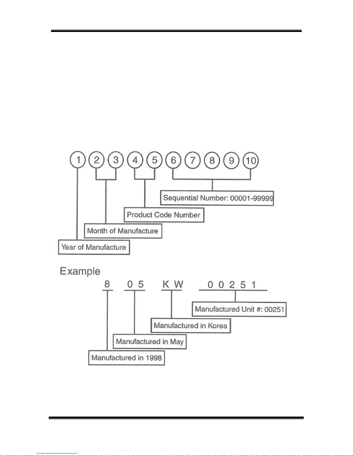
SERIAL NUMBER IDENTIFICATION
The serial number is unique to each product. It gives information concerning the
time and place of manufacture. The serial number is required to be paid for
warranty service and to get the correct part in the event a running production
change was made. Some models may have four (4) letters instead of two (2) for
the product code number. The third and fourth letters are significant only to the
manufacturing facility.
This chart will help you decode the serial number.
WM2496H*M Page 9 of 58 TRAINING MANUAL
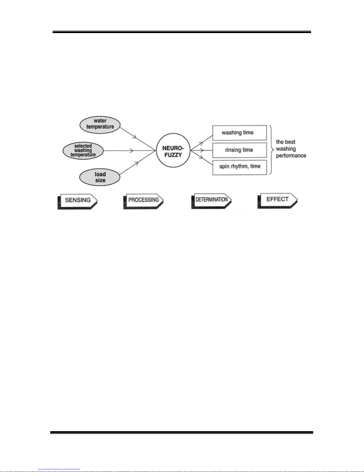
FUZZY LOGIC
To get the best washing performance, the user selects one of the standard
cycles and sensors in the WM2496 make an infinitely variable number of
adjustments as the cycle progresses. Adjustments are automatically made for
load size, incoming water temperature, soil level, rinses required, and other
variables.
DOOR LOCK
The door has an automatic, electrically operated lock system. When the machine
is off or paused, the door can be opened by pulling it. When the machine is
operating, the electric latch keeps the door closed.
The door cannot be opened:
• When the WM2496 is operating
• When the power failed or the washer is unplugged
(until the capacitor discharges and releases the lock)
• When the DOOR LOCK light is on
• When the drum is still turning
DOOR LOCKED LAMP
The DOOR LOCK lamp lights:
• When the WM2496 is operating
• When the water level sensor frequency is lower than 22.9 kHz
• When the temperature inside the tub is over 45° C (113°F)
WM2496H*M Page 10 of 58 TRAINING MANUAL
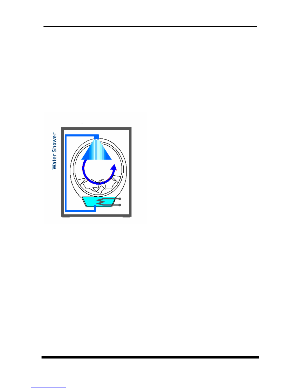
WATER CIRCULATION
The recirculation pump circulates the water during most of the cycle. During the
WASH cycle, it runs continuously for the first 3 minutes and then intermittently
throughout the cycle. During the RINSE cycle, it runs continuously as soon as the
appropriate amount of rinse water has been added. This recirculated water
enters the drum at the top of the door at a small shower head. This spray not
only keeps the window and gasket clean, it allows the clothes to be soaked with
detergent or rinse water more quickly and can be used to control an oversudsing
event.
The recirculation pump is separate
from the drain pump, but they are
attached to opposite sides of the filter
housing.
When the sanitary cycle is used, the
door will remain locked until the
laundry has cooled to a safe
temperature (below 45° C / 113°F).
The pumps and filter are located at
the bottom left front corner. The filter
can be unscrewed, cleaned, and
replaced by opening the small cover.
Use the small drain hose to evacuate
the water remaining in the bottom of
the tub before removing the filter. Do
not pull it out so far the hose is kinked
or water will not flow.
The drain pump is on the left and
exhausts the water via the gray
corrugated hose.
The recirculating pump is on the right
and recirculates water from the tub to
the shower spray at the top of the
door gasket via the smaller black
hose.
WM2496H*M Page 11 of 58 TRAINING MANUAL

PARTS IDENTIFICATION
The air vent on the back of the machine must be left open and clear at all times.
If the washer is installed in a closet or closed laundry alcove, there must be
sufficient clearance and ventilation. The closet should have a full louvered door
2
with at least 350 square inches (0.5 m
) of open area for ventilation.
The washer requires a space of at least 1 inch (2.5 cm) between the wall and the
machine on each side and at least 4 inches (10 cm) between the back of the
washer and the wall. Additional space may be needed for servicing.
WM2496H*M Page 12 of 58 TRAINING MANUAL
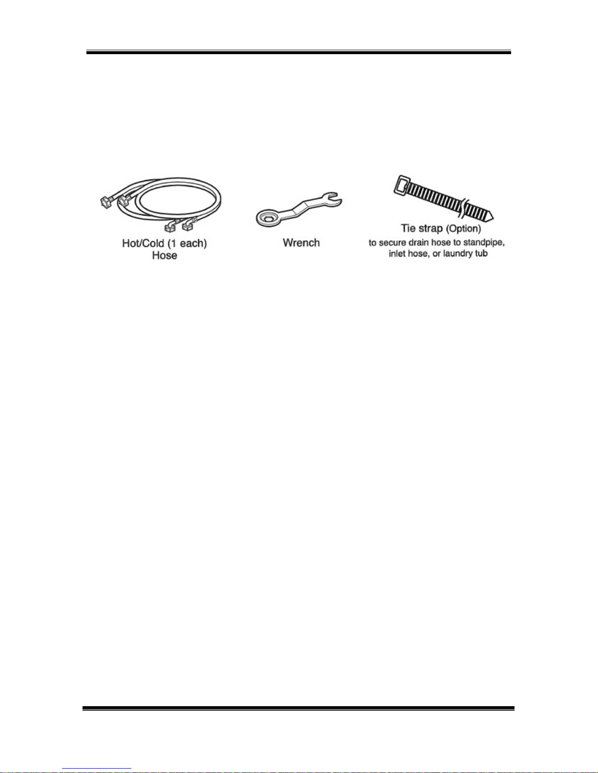
ACCESSORIES
The washer comes with the two input hoses. The blue stripe is for cold water and
the red stripe is for hot water. While the hoses appear to be mechanically
identical, the temperature and pressure ratings are different. It is critical to the
performance of the washer to have the hot and cold hoses connected correctly.
The wrench is used to remove (and replace) the shipping bolts and to adjust the
leveling feet. Be sure to leave it and encourage the customer to retain the wrench,
the four shipping bolts, and the manual in a safe place in the event the washer
requires service or the customer moves.
The shipping bolts MUST BE REMOVED before operating the washer. (See
page 15.) Also check for the packing block, which sometimes remains in the
base when the washer is unpacked.
WM2496H*M Page 13 of 58 TRAINING MANUAL
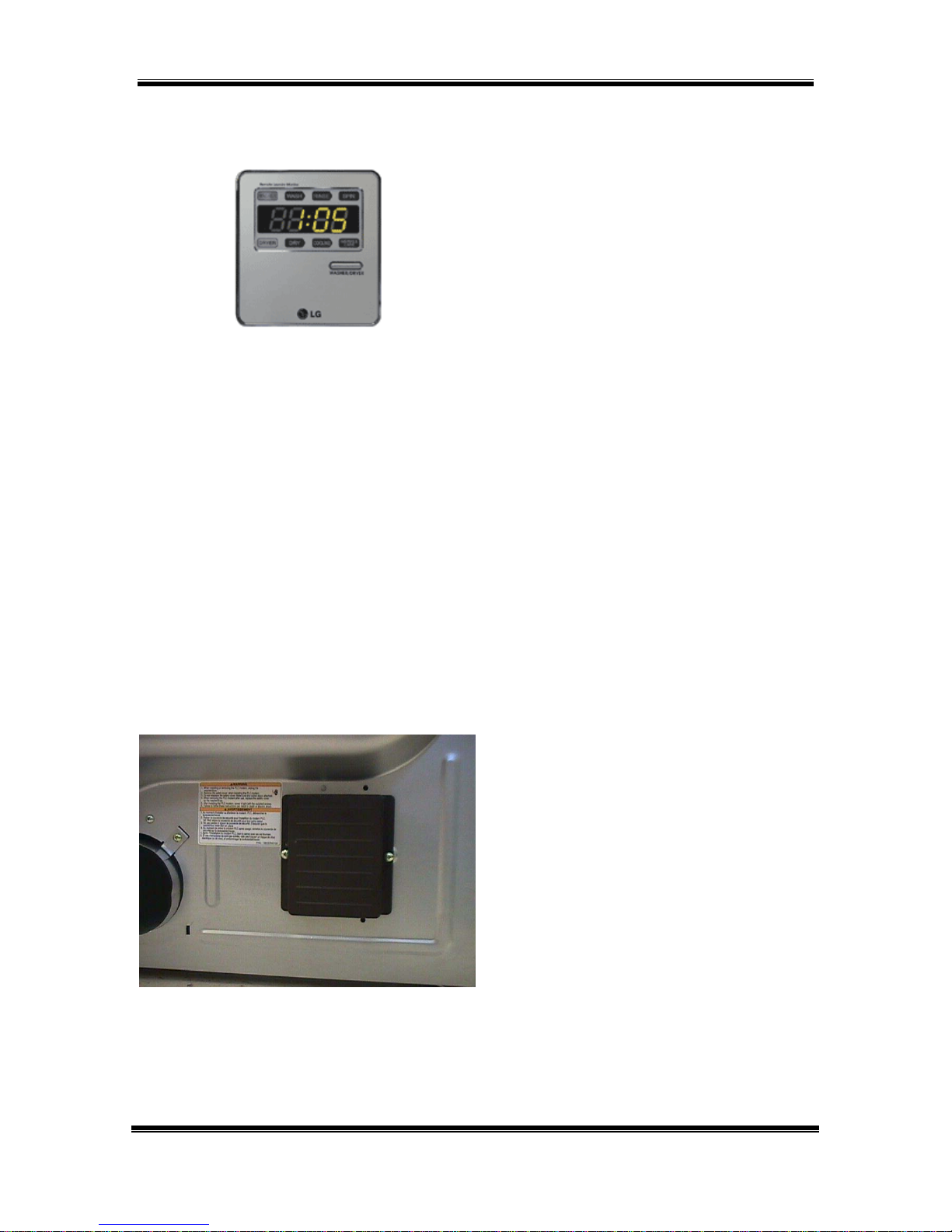
REMOTE MONITOR and MODEM
The remote laundry monitor (RLM)
allows the user to monitor the
progress of both washer and dryer,
provided they are both equipped with
a modem.
Remove the cover and install the
modem on the back of the washer.
Save the small socket cover and
screws in the event you need to
remove the modem for some reason.
The socket should be covered at all
times.
While you’re at it, go ahead and install
the modem on the dryer now.
Remove the cover and install the
modem on the back of the dryer.
Save the small socket cover and
screws in the event you need to
remove the modem for some reason.
The socket should be covered at all
times.
After installation is complete, plug in
the washer, dryer, and monitor, in that
order. Turn on the washer and dryer.
Press and hold the SET button on the
monitor.
WM2496H*M Page 14 of 58 TRAINING MANUAL
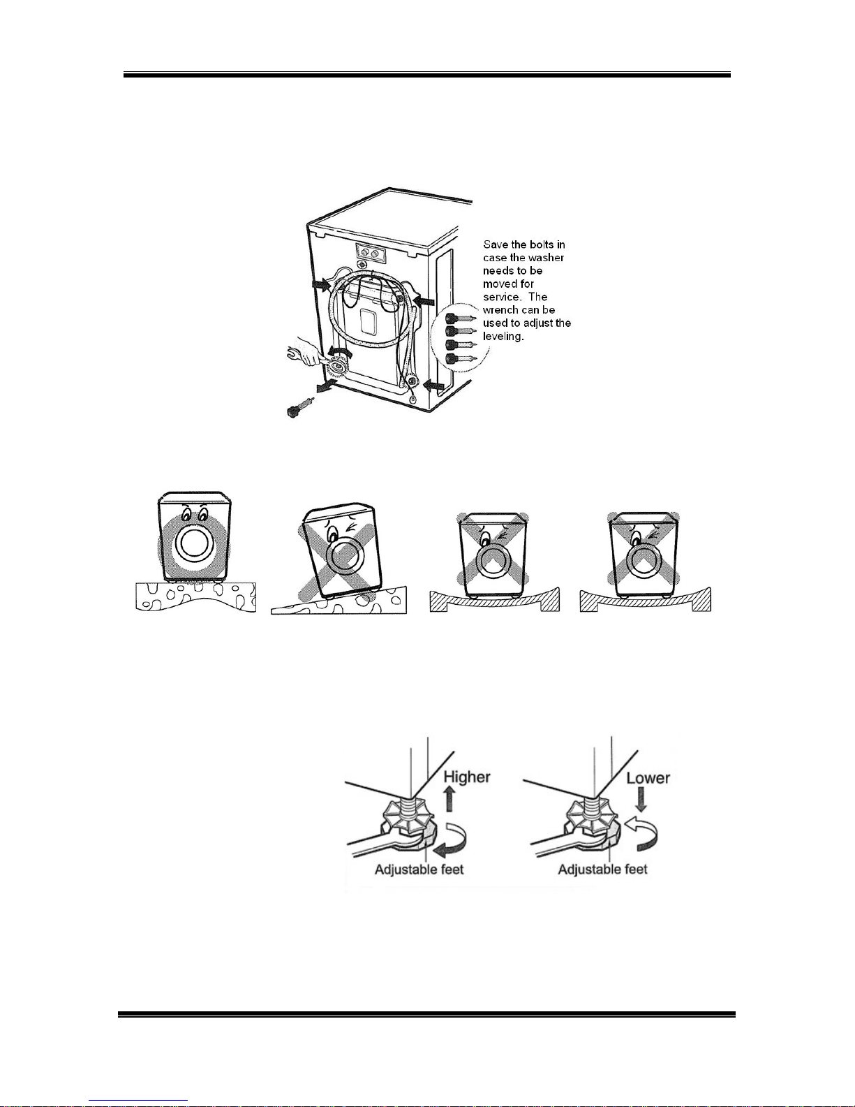
INSTALLATION
REMOVE THE SHIPPING BOLTS.
INSTALL THE WASHER ON A FIRM, FLAT SURFACE.
ADJUST THE FEET TO BE LEVEL.
If you’re installing the washer on a pedestal, install the pedestal now.
(See next page.)
WM2496H*M Page 15 of 58 TRAINING MANUAL
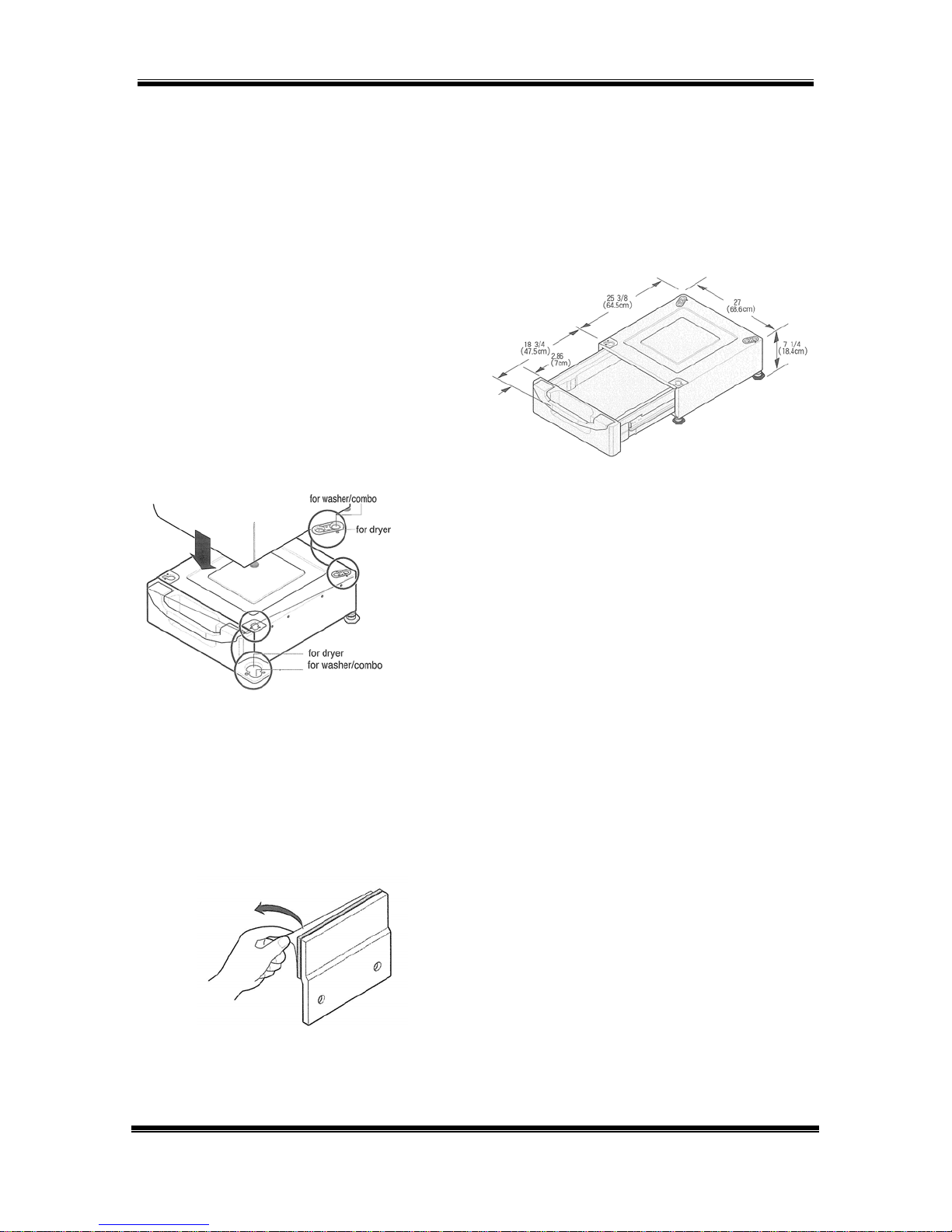
INSTALLATION (PEDESTAL KIT)
This procedure covers installing and leveling the 7½” and 13” pedestals for 27”
washers, dryers, and combos. If the products are stacked, the washer must be
below the dryer, and you’ll use only one pedestal.
1. Remove the pedestal,
installation hardware, and
instructions form the shipping
carton. Set the pedestal as close
to the installation position as
possible.
2. Level the pedestal on a flat, solid
floor before proceeding. Lock
down the rear adjusters but
leave the front ones free for now.
3. Note which holes are for the
washer and which are for the
dryer. If you are stacking the
appliances, the washer must
be on the bottom.
4. Remove the protective paper
from the adhesive surface of the
bracket. Be particularly careful,
because when the adhesive
makes contact, there is no
adjustment possible.
WM2496H*M Page 16 of 58 TRAINING MANUAL
PEDESTAL, continued
5. Depending upon the model, your
pedestal may have straight or
curved brackets. The curved
ones are to be used on the rear
positions when mounting a dryer
to a pedestal, but can also be
used in any other position on the
pedestal.
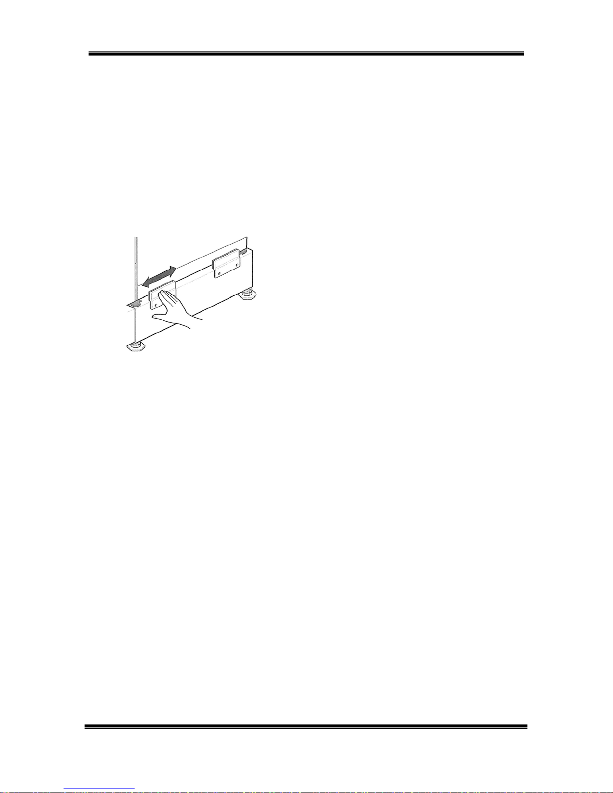
6. Holding the exposed adhesive
away from the appliance, insert
the screws and get them started.
Then press the brackets to the
appliance and tighten all the
screws. Rub the bracket from
side to side to ensure a
complete bond.
7. Use the wrench to turn each leg
of the appliance approximately
¼ turn to put a little pressure
between the appliance and the
pedestal. This will eliminate any
rattles.
8. It is usually easier to set the
pedestal and washer into place
and connect the water and drain
hoses before placing the dryer
on top of them.
WM2496H*M Page 17 of 58 TRAINING MANUAL
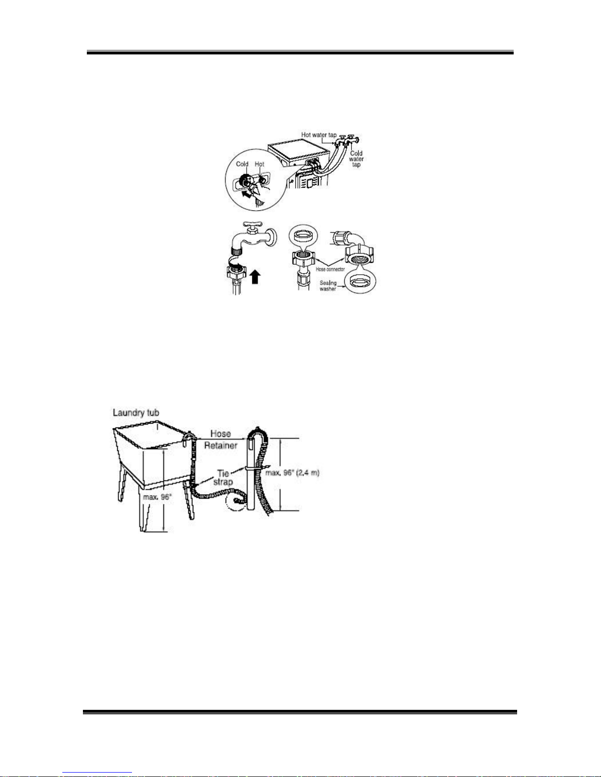
CONNECTIONS
WATER
Be sure the rubber washer is inside the hose end. Attach the hoses to the
washer (red is HOT, blue is COLD). Tighten them firmly but don’t strip the plastic
threads on the washer connections. The hoses may appear to be mechanically
identical, but the hot hose is rated at a higher temperature and burst strength.
DRAIN
The drain pipe should be firmly attached to the standpipe or the laundry tub or
sink where it drains. The pump has sufficient power to cause the pipe to move
around when the water is expelled. The pump can lift the drain water a maximum
of 96 inches (2.4 m), but there is no minimum height requirement. The vacuum
breaker in the drain line will prevent drainage by gravity or siphoning. The hose
can lay flat into a floor drain as long as the end of it is not submerged.
ELECTRICAL
The WM2496 washer requires a 120 VAC, 60 Hz., dedicated, 20-amp circuit.
WM2496H*M Page 18 of 58 TRAINING MANUAL
 Loading...