

LG WF-T7516HN Owner’s Manual
Owner's Manual
Please read this manual carefully and thoroughly
before operating this unit.
Record model name and serial number of the set.
Quote this information to your dealer when you
require service.
MODEL : WF-T7516HN
F
OF
O
AUT
3
Fuzzy
T
m
Econoy
TAR
S
3
E
Jean
Turbo
US
PA
ol
o
W
Wash
r
Hou
Rinse
ergent
t
De
r
t
Spin
ae
W
Min.
Delay
OR
P
Ex-Large
Time
M
R
Large
GA
Left
Extra Wash
-RO
o
Medium
Ht
P
Extra Rinse
Small
S
S
E
Cold
m
k
r
C
a
c
W
YD
Gentle Spin
C
A
L
o
h
E
L
i
l
d
TAR
R
ST
ATE
W
ER
A
WAT
WSH
.
LEVEL
P
TONI
TEM
OP

ontents
C
Read this manual
Inside you will find many helpful hints on how to use and maintain your washer properly. Just a little
preventive care on your part can save you a great deal of time and money over the life of your washer.
You will find many answers to common problems in the Troubleshooting section. If you review our
chart of Troubleshooting Tips first, you may not need to call for service at all.
Introduction
Installation
Before Starting to Wash
Washing Programs
Function Options
Maintenance
Troubleshooting
Specification
Product Features
Safety Information
Identification of Parts
Placing, Leveling and Installation
Connecting Water Supply Hose
Connecting Drain Hose
Grounding Method
Care Before Washing
Preparation for Washing
Use of Water, Detergent, Bleach and Softener
Water Level and Amount of Detergent
Use of Bleach
Use of Softener
Stain Removal Techniques
Function of each Button
Fuzzy Wash (Normal Wash)
Economy Wash
Jean Wash
Wool Wash
Turbo Wash
Washing Process
Delay Start (Reservation) Wash
Child Lock, Mute
Cleaning Inlet Valve Filter
Cleaning Lint Filter
Cleaning and Maintenance
Quick Reference for Cloth Weights
Common washing problems
Troubleshooting
Specification
3
4
5
6
7
9
10
11
11
12
13
13
14
15
16
18
18
18
18
18
20
22
22
24
24
25
26
27
28
29
2
Contents

roduct Features
P
Washer doesn't operate while the lid is open. If the lid is open during the wash,
rinse or spin cycles, the operation stops for safety.
Fuzzy Logic Control
A built-in load sensor automatically detects and measures the laundry load and
a microprocessor optimizes washing conditions such as ideal water level,
washing time and optimum detergent quantity indication.
Advanced technology is built into the Electronic Control System which ensures
the best washing result.
START
SENSING
Laundry Sensor
Water Level
Sensor
SETTING
Optimum
Washing
Condition
WASHING
AUTO
POWER
OFF
Turbo drum washing
When "Punch + 3" washing wings turn, the washing tub turns in the
opposite direction. This makes the both sides current of water which
improve washing-performance by rubbing clothes strongly.
3 Step washing
3 step washing makes best washing performance with low tangling.
Rubbing
Rubbing and
Shaking
Shaking and
Disentangling
Auto Restart
In the event of a power failure, the washing machine will automatically start its
cycle from the point of interruption when power is resumed.
Lint Filter
Lint and loose threads from laundry generated during the
washing cycle are caught by the lint filter for a cleaner wash.
ATTENTION
Be sure to remove the unit from all packing base, otherwise the
machine will not be able to operate properly.
Introduction
3
afety information
S
Manufacturer is not responsible for accidents caused by the user as a result of not following the
user's guide.
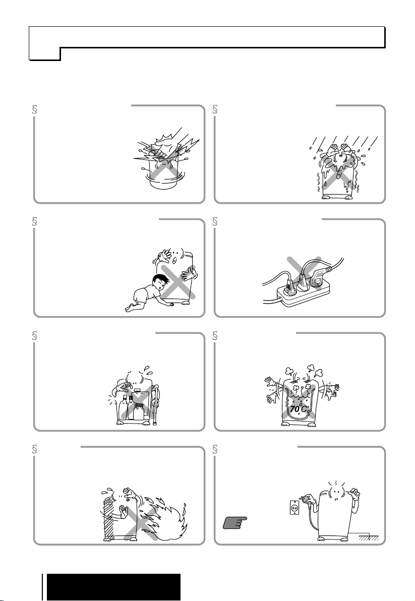
In Operation
l
Do not insert the hand inside the inner-tub during operation. Hands may get caught
in the laundry.
l
If the machine does not stop
operating up to 15 seconds
after opening the lid, stop
using the machine and
contact Area Service center
for repair.
Children's Safety
l
Do not let children climb on top of the machine or
climb into the inner-tub.
l
Do not let children insert the hand
into the bottom of the machine
where is a revolving part.
Injury may occur!
Volatile Material
l
Do not wash or dry clothes stained with volatile
material such as Benzene or thinner. It may
cause an explosion,
fire or burn.
Installation Area
l
Avoid area exposed to snow, rain, or where
humidity is high. Avoid water-contact to the
switch area. It may cause
electric shock or
malfunction.
Electric Outlet
l
Avoid connecting several electric devices into a
single outlet. It may cause a fire.
Hot Water
l
Avoid using hot water over 70°C. It may deform
plastic parts or cause malfunctions.
Heat
l
Avoid electric heaters, candles, cigarette lighters,
bug smokers, etc., near the machine. It may ignite
or deform plastic parts.
4
Introduction
Grounding
l
Before connecting the power cord, make sure to
ground, otherwise it may cause
electric shock.
10
Refer Page No.
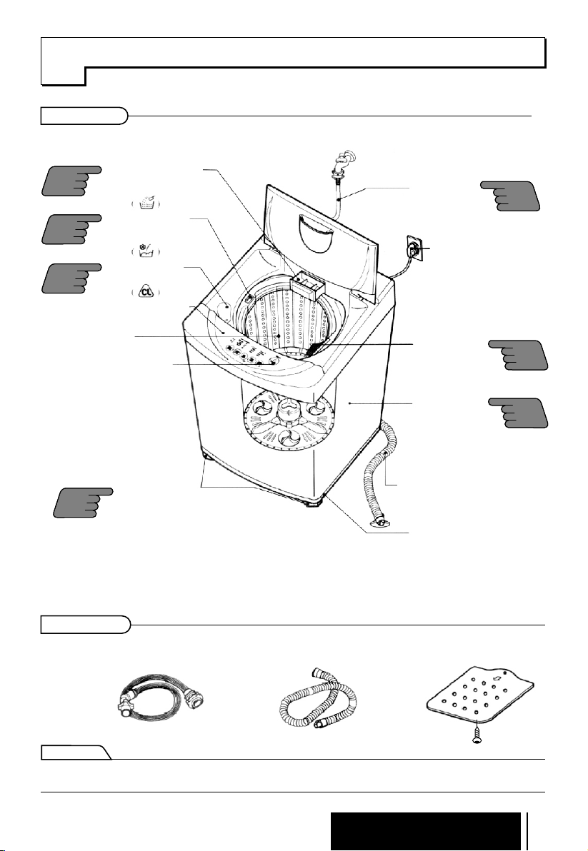
dentification of Parts
I
Body
POWDER DETERGENT
12
14
13
BOX FOR DELAYED
WASHING
*
SOFTENER INLET
Softener will automatically
flow into the tub.
INLET HOLE F OR
BLEACH
FUNCTION SELECTOR
*
TUB
START/PAUSE
*
BUTTON
Use to start or stop the
washing machine
temporarily.
*
WATER SUPPLY
HOSE
Make sure the water
does not leak.
*
POWER PLUG
If the supply cord is
damaged, it must be
replaced by the
manufacturer
or its service agents
or similarly qualified
person in order to
avoid a hazard.
LINT FILTER
Clean regularly to stop
linting on the clothes
load.
*
CASTER
Use for easy translocation
7
24
6
ADJUSTABLE LEGS
6
(2 adjustable legs are optional. Some models have provision for only 1 adjustable leg).
Use to level the washing
machine for correct balance
& spin operation.
WASHING WINGS
Vertical movement of washing punch can be operated when a sufficient amount of laundry is deposited.
Accessories
Water supply hoses
Note
"*" Parts can be different according to the model.
Drain hose
DRAIN HOSE
Keep the drain hose
flipped down while
washing is in process.
BASE
Anti-rat cover
Introduction
Screw
5
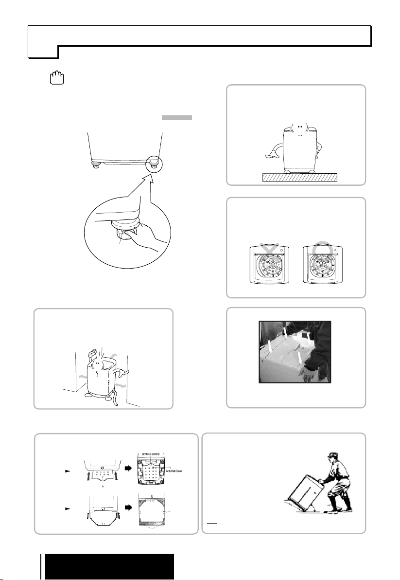
lacing, Leveling and Installation
P
Improper installation of the washer may cause noise and malfunctioning.
1.
The ventilating openings in the base area must not be obstructed by carpeting when the washing machine is
CAUTION
installed on a carpeted floor.
Install the washing machine on a level and firm
2.
surface, any tilt should be less than 4°.
How to adjust leveling
Adjustable leg
Turn the adjustable legs to set the washer
(2 adjustable legs are optional. Some models have provision for only 1 adjustable leg).
H
Distance between drain hose and the wall
Distance between drain hose and the wall should be more
than 10cm, and the distance between the other part or the
rear part and the wall should be more than 2 cm.
horizontal (Both the front legs).
Don't add anything under back side legs.
.
More than 2cm
Installation area
1
Install the washer on flat and firm surface.
Checking level
2
The Basement is not flat, fill the water just touching the
Pulsator and see uniform distribution. If not, adjust the
legs as shown in the figure.
Top View
Checking Proper placement
3
More than 2cm
Anti-rat cover installation
Insert the anti rat cover firmly from back side or
Front side of washing machine and screw it.
High Base
Low Base
6
Installation
More than 10cm
FIXING POSITION
Adjustable Leg
Screws
Anti Rat Cover
Press the corners of the m achine diagonally
as shown in the figure, I f any movement is observed,
adjust the legs for proper l eveling.
Moving of the Machine
Casters are provided for easy translocation of your machine
* Grip the machines properly as shown in fig.
* Tilt the machine towards your side at a angle
O O
45 ~ 55 .
Casters
Note : * Be careful that you should not drop the machine.
* Never move the machine on casters when there is load inside.
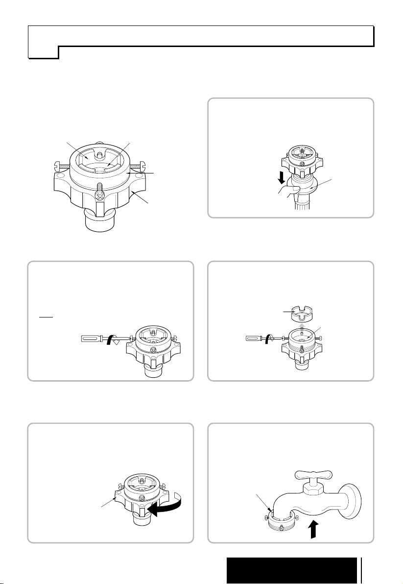
onnecting Water Supply Hose
C
How to connect the water tap
connector
Guide ring
Loosening fixing screws
Rubber packing
Water Tap
connector
Middle connector
2
Loosen the 4 fixing screws of the water tap connector
To fit it on thewater tap.
Note : Loosen the screws up to wall of the water tap
Connector.
Disconnecting the middle connector
from the drain hose
1
Push the connection coupling down as in the figure.
While pressing the connecting coupling disconnect
The water hose by pulling
Connecting
coupling
When the water tap diameter is big or a rectangular
water tap is used, unscrew the four fixing screws and
remove the guide ring as in Fig. 3.
Guide ring
Rubber packing
Seperate Middle connector from water tap
Connector
3
Seperate the middle Connector by rotating middle
Connector as shown in the direction.
Middle connector
Push up the water tap connector
4
Push the connector up the water tap and make sure
that the rubber packing inside the connector is completely attached.
Water tap
Connector
Installation
7
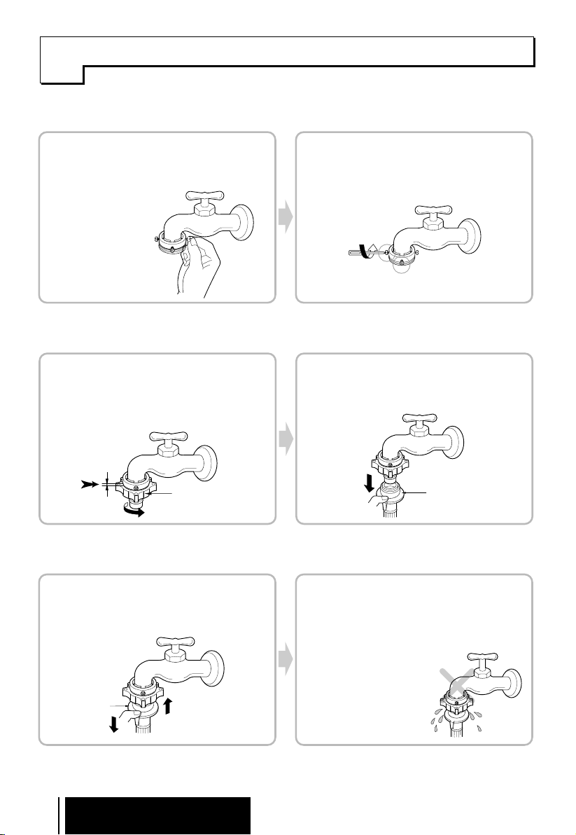
onnecting Water Supply Hose
C
Fixing the connector Tightening fixing screws of the connector
5
Rotate the 4 screws uniformly up to touching the
water tap. Make sure the water tap must be center
Of the connector.
Fixing the Middle connector with water
Tap connector
7
Turn the middle connector as shown in the direction
till completely tightened (with a little force by hand)
Less than 3mm
Check
Middle connector
6
Tighten the two screws marked below, while pushing
Up on the Water tap connector.
Connecting coupling to middle connector
8
Push down the connecting coupling of the water hose.
Connecting
coupling
Connecting the middle connector and
water hose
9
While pulling the connecting coupling connect the hose
To middle connector.
Middle
Connector
8
Installation
Checking connection of the water
0
1
hose and middle connector
Connect the water hose to the washing machine, and
then see if there is any leakage after opening the
water tap. If there is leakage, close the water tap and
start again from Fig. 1. (Improper installation of Fig. 4
and Fig. 7 may cause leakage)
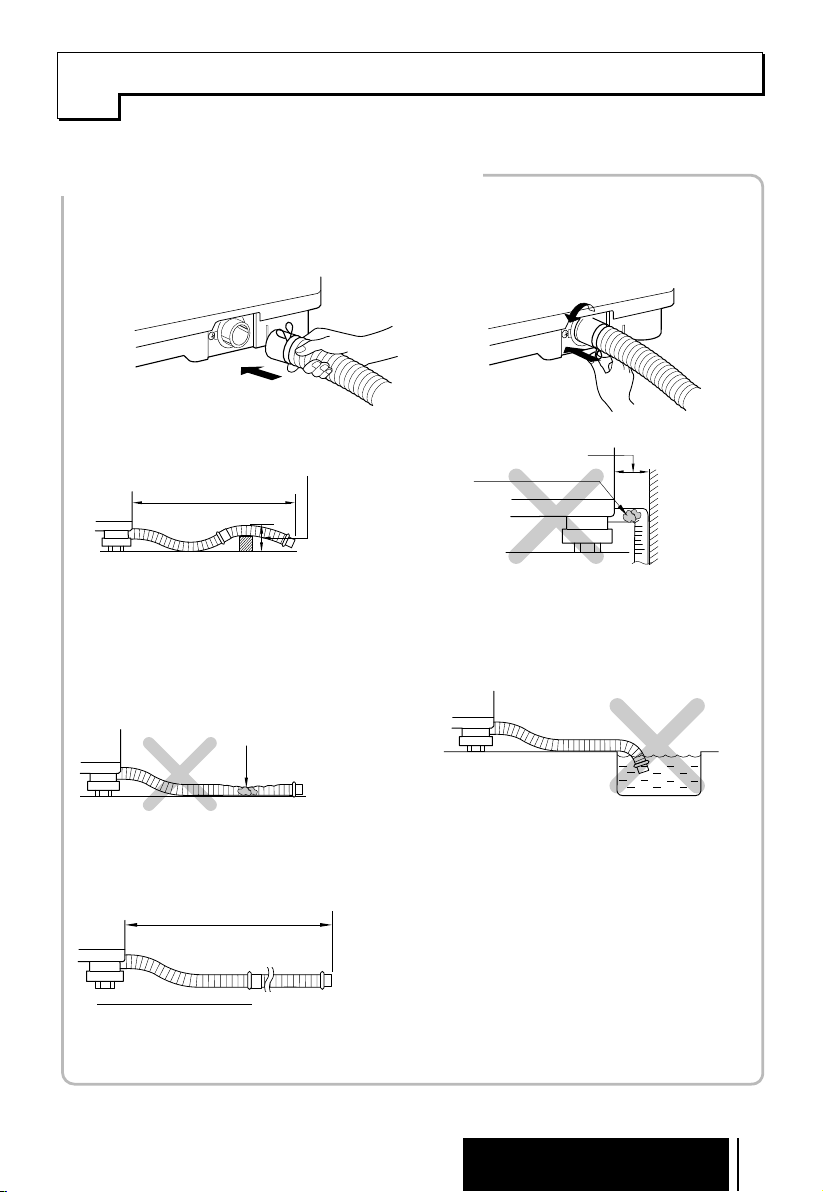
onnecting Drain Hose
C
§ How to connect the drain hose
Insert the drain hose to the connecting area at the body.
1 2
1.
Press the hose clip.
2.
While pressing, push the hose towards
the body.
Release the hose clip after pushing the
3.
hose.
Less than 2m
The hose is placed
over a doorsill.
The hose is clogged by
alien substances.
Make sure that the
hose is not crushed.
Less than 3m
Less than 6cm
Less than 10cm
Make sure that the hose is
not crushed between the
wall and the washer
Avoid submerging
the end of hose.
.
Extension hose is
used.
Installation
9
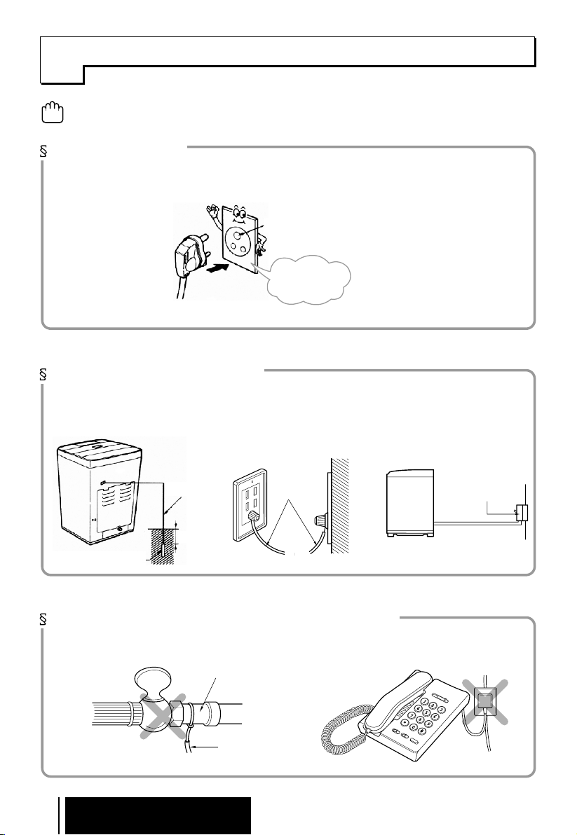
rounding Method
G
Make sure to connect the ground wire
CAUTION
Otherwise, it may cause electric shock!
.
How to ground
l
If AC outlet with ground terminal is used, grounding is not needed.
Ground terminal
Grounding is
not needed
Other grounding method
l
Connect the ground wire to the
ground copper plate and then
bury it under the moist ground at
least 75cm deep
.
Ground Wire
l
Connect the ground wire to the
ground terminal at the outlet.
ground wire
l
When installing it in an area
where grounding is not possib
purchase a short-circuit break
er(15mA at operation, 7.5mA at
idle) and connect it to the outlet.
Short-circuit breaker
le,
-
75cm
Ground Copper Plate
Place where grounding should be avoided
l
Never connect the ground wire to gas pipes, water pipes, lightning arrest or telephone outlets.
l
There is no ground effect in the plastic water pipe.
Gas pipe
Ground wire
10
Installation
 Loading...