

LG WD-P1410BRD, WD-14831RD, WD-1409RD1, WD-1409RD2, WD-1409RD3 Service Manual
...
website : http://biz.lgservice.com
e-mail : http://LGEservice.com/techsup.html
WASHING MACHINE
SERVICE MANUAL
CAUTION
READ THIS MANUAL CAREFULLY TO DIAGNOSE TROUBLES
CORRECTLY BEFORE OFFERING SERVICE.
MODEL : WD-1409RD(1~9)/WDP1103RD(1~9)/WM3455H*

51
P/No.: MFL30574764

CONTENTS
1. SPECIFICATIONS ............................................................................................................................. 3
2. FEATURES & TECHNICAL EXPLANATION ..................................................................................... 4
3. PARTS IDENTIFICATION ................................................................................................................. 6
4. INSTALLATION .................................................................................................................................. 7
5. OPERATION ................................................................................................................................... 12
6. WIRING DIAGRAM / PCB LAYOUT / PROGRAM CHART ............................................................ 14
7. TROUBLESHOOTING......................................................................................................................18
7-1.BEFORE PREFORMING SERVICE ......................................................................................... 18
7-2.LOAD TEST MODE .................................................................................................................. 18
7-3.HOW TO KNOW THE WATER LEVEL FREQUENCY ............................................................. 19
HOW TO KNOW TO TEMPERATURE OF EACH THERMISTOR AT OPERATING CONDITION
7-4.
7-5.ERROR DISPLAY ..................................................................................................................... 20
7-6.TROUBLESHOOTING WITH ERROR ..................................................................................... 21
• IE (Water Inlet Error) .............................................................................................................. 21
• UE (Unbalanced Error) ........................................................................................................... 22
• OE (Water Outlet Error) .......................................................................................................... 23
• FE (Flow over Error) ............................................................................................................... 25
• PE (Pressure Sensor S/W Error) ............................................................................................ 26
• DE (Door open Error) ............................................................................................................. 27
• tE (Thermistor (Heating) Error) ............................................................................................... 28
• LE (Motor Lock Error) ............................................................................................................. 29
• DHE (Dry Heater Error) .......................................................................................................... 31
• Dry Heater Trouble ................................................................................................................. 32
• Dry Fan Motor Trouble ............................................................................................................ 33
.. 19
8. TROUBLESHOOTING ELSE ..........................................................................................................34
• No Power ................................................................................................................................ 34
• Vibation & Noise in spin ......................................................................................................... 35
• Detergent & Softener does not flow in .................................................................................... 36
• Water Leak ............................................................................................................................. 37
9. DISASSEMBLY INSTRUCTIONS ................................................................................................... 39
10. EXPLODED VIEW ......................................................................................................................... 47
2
3
1. SPECIFICATION
ITEM
POWER SUPPLY
PRODUCT WEIGHT
OPERATION WATER PRESSURE
CONTROL TYPE
WASH & DRY CAPACITY
DIMENSION
WASH PROGRAM
RINSE
DOOR SWITCH TYPE
WATER LEVEL
RESERVATION
SENSING OF THE LAUNDRY AMOUNT
FUZZY LOGIC
DISPLAY OF THE REMAINING TIME
ERROR DIAGNOSIS
POWER AUTO OFF
CHILD LOCK
AUTO RESTART
TIME SAVE
ELECTRICITY
CONSUMPTION
WASHING
SPIN
DRAIN MOTOR
STEAM HEATER
WASH HEATER
DRY HEATER
REVOLUTION
SPEED
WASH
SPIN
No Spin/400/800/1000/1400
50rpm
1.0-8bar (100-800kPa)
Electronic
Refer to the Rating Label
600mm(W)x640mm(D)x850mm(H)
Cotton, Cotton Quick. Synthetic, Delicate, Hand Wash,Wool,
Quick30, Duvet, Baby Care
Rinse+Spin, Rinse+, Normal+Hold
Bi-Met
al type
10 steps (by senso
r)
From 3 hours to 19 hou
rs
Adapted
Adapted
Adapted
10 i
tems
Adapted
Adapted
Adapted
Adapted
140W
440W
30W
1100W
2000W
1500W
127V~, 60Hz
72kg
WD-1409RD(1~9)/WDP1103RD(1~9)/WM3455H*
2. FEATURES & TECHNICAL EXPLANATION
2-1. FEATURES
Direct Drive System
The advanced Brushless DC motor directly drives the drum without belt and pulley.
Water Circulation
Spray detergent solution and water over the load over continu.
Clothes are soaked more quickly and thoroughly during wash cycle.
The detergent suds can be removed more easily by the water shower during rinse cycle.
The water circulation system uses both water and detergent more efficiently.
Built-in Heater
Internal heater automatically heats the water to the best temperature on selected cycles.
Child Lock
The Child lock prevents children from pressing any button to change the settings during
operation.
More economical by Intelligent Wash System
Intelligent Wash System detects the amount of load and water temperature, and then
determines the optimum water level and washing time to minimize energy and water
consumption.
Low noise speed control system
By sensing the amount of load and balance, it evenly distributes load to minimize the
spinning noise level.
Automatic Wash Load Detection
Automatically detects the load and optimizes the washing time.
4
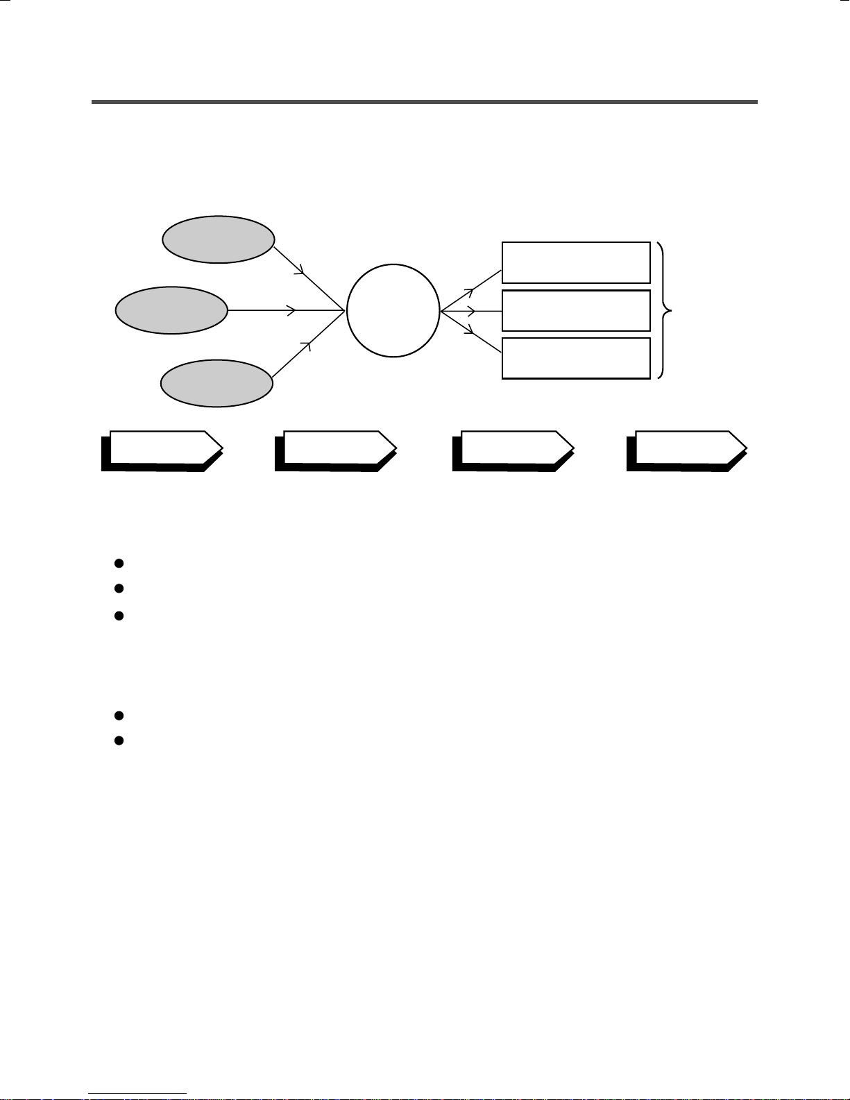
2-2. DETERMINE WASHING TIME BY FUZZY LOGIC
To get the best washing performance optimal time is determined by sensing of water temperature,
selected washing temperature and laundry amount.
water
temperature
washing time
selected
washing
temperature
SENSING
laundry
amount
PROCESSING
FUZZY
LOGIC
rinse time
spin rhythm, time
DETERMINATION
EFFECT
2-3. WATER LEVEL CONTROL
This model adopts a pressure sensor which can sense the water level in the tub.
Water supply is stopped when the water level to the preset level, then washing program proceeds.
Spinning does not proceed until the water in the tub reduces to a certain level.
2-4. THE DOOR CAN NOT BE OPENED
the best
washing
performance
While program is operating.
While Door Lock light turns on.
5
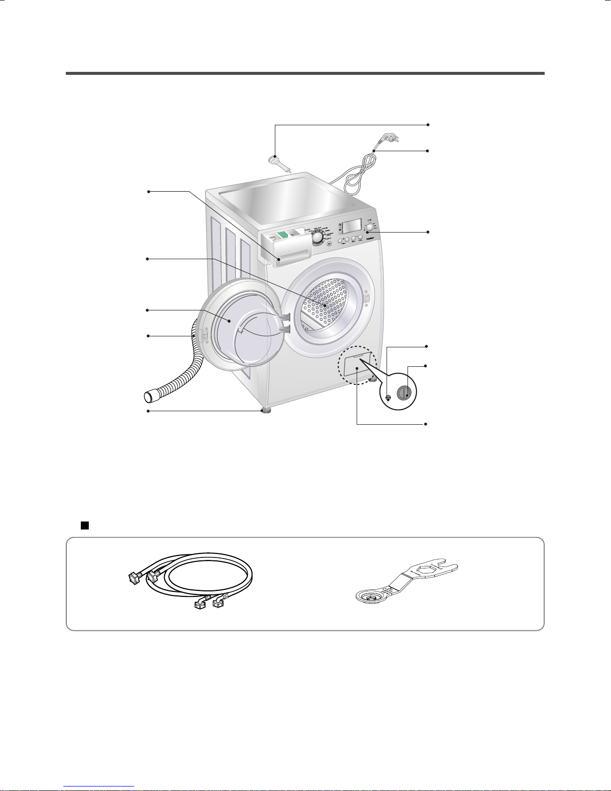
3. PARTS IDENTIFICATION
Drawer
Drum
Door
Drain Hose
Shipping Bolts
Power Pulg
If the supply cord is damaged,
it must be replaced by the
manufacturer or its authorized
service technician in order to
avoid a hazard.
Control Panel
Drain Plug
Adjustable Feet
ACCESSORIES
Inlet hose(2EA)
Drain Pump Filter
Lower Cover Cap
Spanner
6
4. INSTALLATION
INSTALLATION
The appliance should be installed as follows.
1
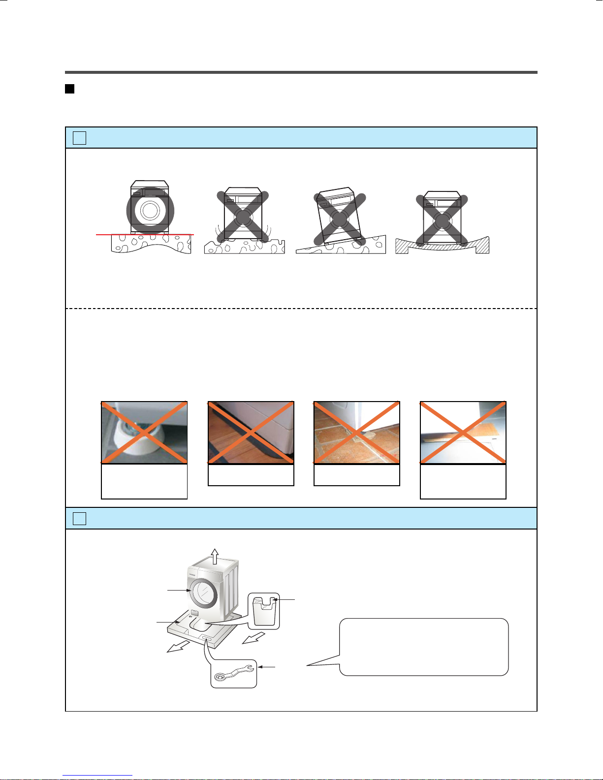
Check the conditions of installation area.
1. Check level ground.
horizontal
On raised foundations or upper level homes, the vibrations can be caused by the type of flooring.
It may be necessary to move the machine to a different area in the home or have the floor
reinforced to properly support the operation of the unit.
2. Check humidity or any foreign objects under the feet.
Clean the floor, and there should not be any foreign objects under the feet.
If the unit has foreign objects underneath the feet, this will prevent the unit from being leveled properly
and will cause vibrations and slipping.
Remove any foreign objects, if any from underneath the machine and level unit properly.
See below for examples of foreign objects.
Purchased
Capet Paper Laminated
stopper
2
Open the box and check appliance condition.
Washer
Base Packing
Packing Support
(Packing support may not be used depending on models.)
Wrench
paper
This leveling (or spanner) wrench must
be used to remove the shipping bolts
and level the unit. This should be kept
for future use.
7
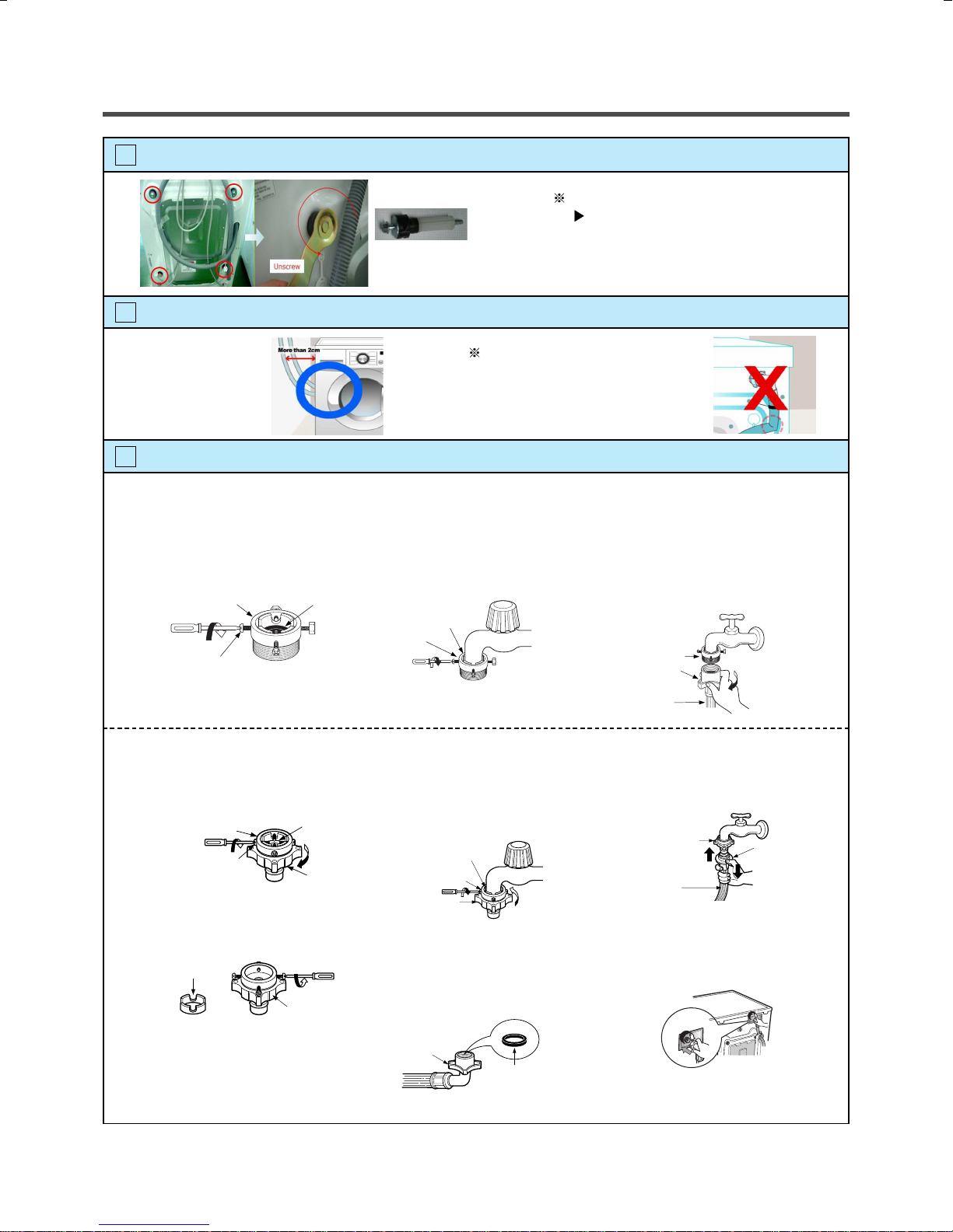
3
Use spanner to remove transit bolts.
Without removal of transit bolts
X 4 EA
Transit bolts
4
Confirm the distance between the appliance and the wall.
Spin noise and shaking.
More than 2cm
If the distance is less than 2cm,
the water supply hose will
kink or fold.
5
The tap connection and hose connection must be parallel.
1. Normal Tap without thread & screw type inlet hose.
1. Unscrew the fixing screw to
attach the tap.
Upper
Connector
Fixing screw
Rubber
packing
2. Push the connector up till the
rubber packing is in tight contact
with the tap. Then tighten the 4
screws.
Rubber packing
Upper
Connector
3. Push the water supply hose
vertically upwards so that the
rubber packing within in the hose
can adhere completely to the tap
and then tighten it by screwing it
to the right.
Upper
Connector
2. Normal Tap without thread & one touch type inlet hose (Single inlet models)
1. Untighten the upper connector
screw.
Upper
Connector
Fixing screw
• In case the diameter of the tap
is large remove the guide plate.
Guide plate
Rubber
packing
Middle
connector
Connector
2. Push the upper connector up
till the rubber packing is in
tight contact with the tap. Then
tighten the 4 screws.
Rubber packing
Upper
Connector
Middle
connector
• Turn the middle connector not to
have water leaked.
•Make sure that the rubber seal is
inside the hose connector.
3. Connect the water supply hose
to the middle connector, pushing
the plate down.
• To separate the water supply
hose from the middle connector
shut off the tap.
Then pull the inlet hose down,
pushing the plate down.
Plate
Water supply
hose
Upper
Connector
Water supply
hose
Plate
Hose connector
8
Rubber seal
• Make sure that there are no
kinks in the hose and that it is
not crushed.
6
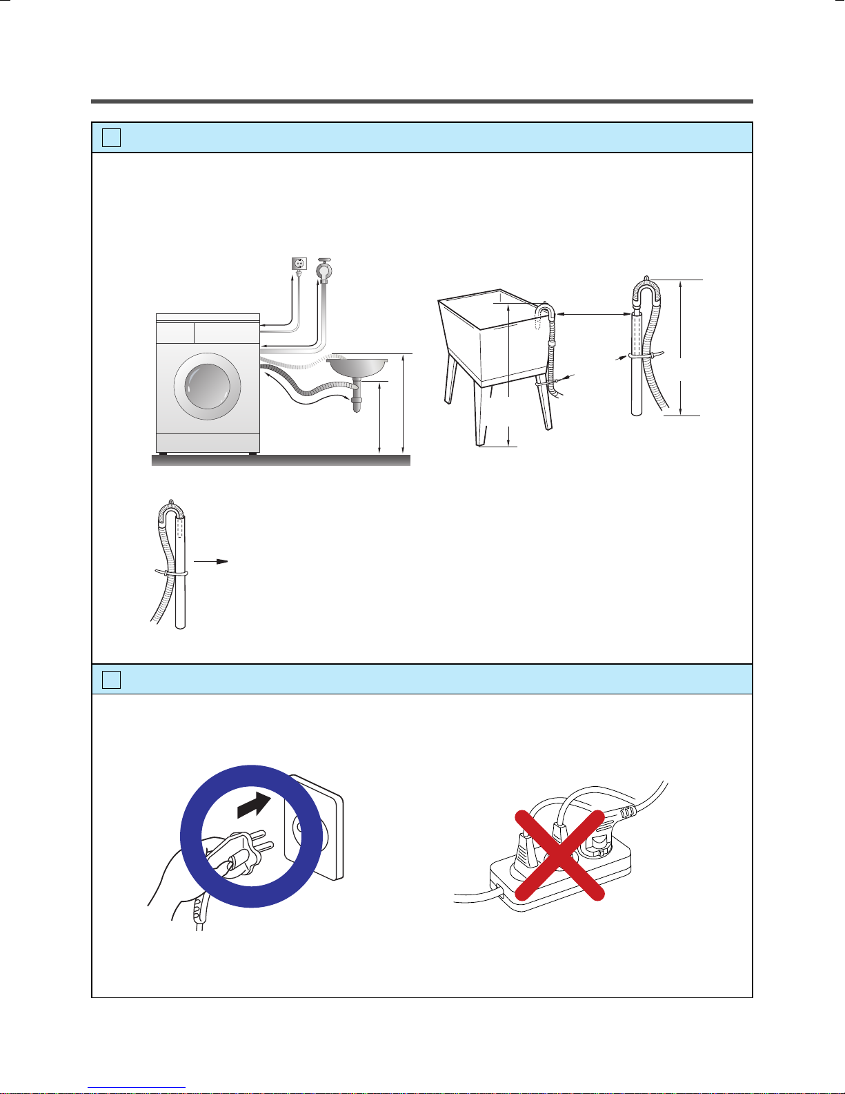
Connect Drain Hose.
If the drain hose is not installed properly, the unit will not drain properly.
This allows water to back flow into the unit which can cause odors.
Refer to Owner Manual for proper drain hose installation.
The odor could also be coming from the home’s drain to which the drain hose is attached.
Laundry tub
about 100 cm
about 145 cm
Hose
Retainer
Tie
strap
about 105 cm
max. 100 cm
min. 60 cm
Max. 100cm
min. 60cm
In this type of drain hose installation, the odor could be coming from the standpipe.
This odor can come up the drain hose and into the unit.
Pour a cup or two of bleach or vinegar down the home drain
and let it sit for 24 hours before running another cycle.
This will help eliminate odor from the home drain.
If a cycle is started too soon after doing this, it will not help the issue.
7
Connect power plug.
Connect the power plug to the wall outlet. Avoid connecting several electric devices,
it may be the cause of a fire.
Max. 100cm
min. 60cm
9
8
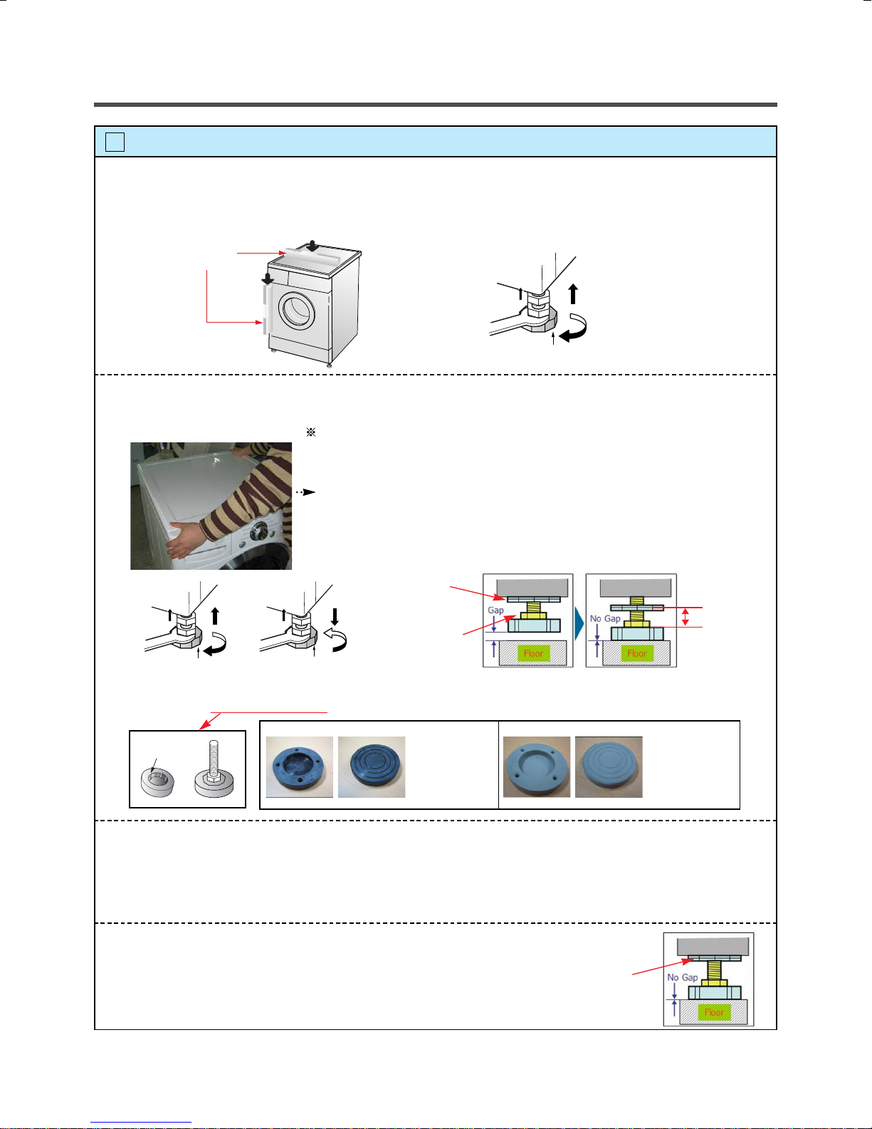
Check the horizontality with a level (Gage).
1 Step
If washing machine legs are loose or not screwed, then screw up with the spanner wrench.
Using the level, level the washing machine from front to back and side to side.
A level
Higher
Tighten
Adjustable feet
2 Step
Using the spanner wrench to adjust leg for horizontality and try for Diagonal test.
Diagonal test
How to perform a diagonal test:
Place your right hand on the back, right corner and your left hand on the front,
left corner of the unit, then attempt to rock the unit from corner to corner.
Then, move your right hand to the front, right side and your left hand to the
back, left corner and attempt to rock the unit from corner to corner.
If the unit is level, it will not rock. However, if the unit is not level, it will rock.
If the unit rocks, it will be necessary to adjust the leveling feet of the unit.
Adjust the foot under the hand that is on the front of the machine.
Lock nut
Adjustable bolt
Tighten
Higher
Adjustable feet
Lower
Tighten
Adjustable feet
Lower the foot until there is no gap between floor and foot.
And only use adjustment rubber when difference at the leg adjustment is more than 10mm.
Rubber Cup
4620ER3001A
(Black)
for Tile floors
4620ER3001B
(Gray)
for Wooden floors
3 Step
Perform a Rinse and Spin with some clothing in the machine.
To do this, put 2~3kg of clothing in the unit, power on the unit, press the Rinse and Spin
button, and then start. When the unit reaches the spin cycle, watch for vibrations.
If the unit is vibrating, make small adjustments to the leg until they subside. (Try 2Step again)
10mm
4 Step
Tighten the lock nut against the base of the machine to lock the position leg.
Tighen the lock nut
10
9
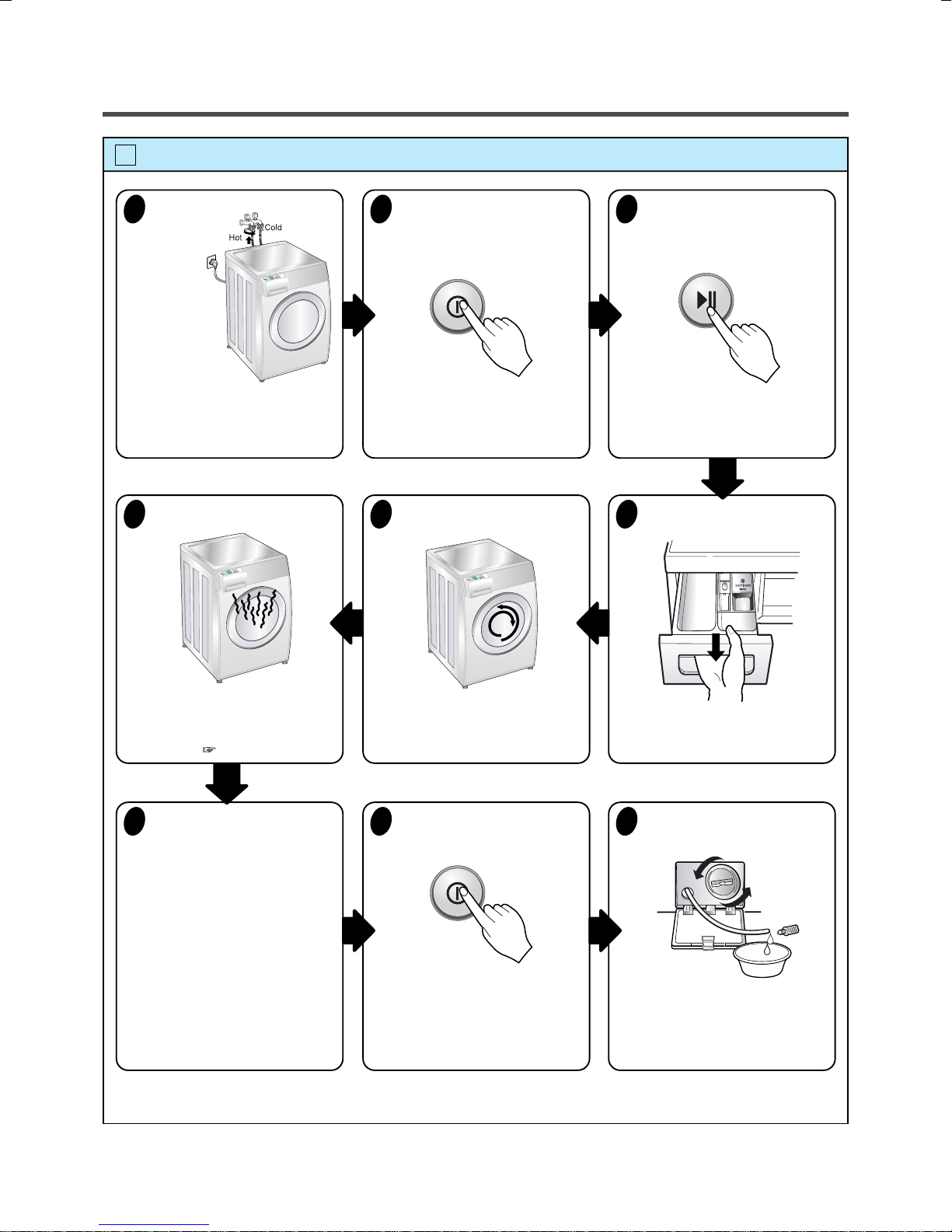
Test operation
Preparation
1
for
washing.
· Connect the power plug to the
outlet.
· Connect the inlet hose.
Check the water heating.
6
Press the power button.
2
Check automatic reverse turn.
5
Press the START/PAUSE
3
button.
· In case of Coloreds program.
Check the water supply.
4
· Press the Option(Left) + Temp.
button simultaneously and the
present temperature will be
displayed.
Check drain and spin.
7
· Turn off Wash and Rinse after
pressing the Start/Pause button
and start the machine again.
· Check drain and spin.
Page 13
· Check if the drum rotates
clockwise and counterclockwise.
Power off and open the
8
door.
· Power off and then power on.
· Check if the door can be
opened after 3 minutes.
· Check if water is supplied through
the detergent dispenser.
Water removal.
9
· If SVC is needed during check,
remove the remaining water by
pulling out the hose cap.
11

5. OPERATION
Cycle Selector
• Rotate the Cycle selector
knob to select the cycle
designed for different
types of fabric and soil
levels.
Power
• Use this button to turn the
power On/Off.
Additional programs
•Time Delay : Allows the start of any cycle to be
delayed for 3~19 hours.
• Favorite :
customized operation for next use.
• Intensive : If the laundry is heavily soiled “Intensive”
option is effective.
•Medic Rinse : For high effectiveness or more purity in
rinse operation you can choose Medic Rinse option.
Medic Rinse is default in Baby Care program.
Favorite program allows you to store a
Start/Pause
• Use this button to Start/
Stop the washer.
Option Button
• Pre Wash : If the laundry is heavily soiled, “Pre Wash” Cotton is
recommended.
• Rinse+ : Used to additional rinse, which may assist in removing
traces of detergent residue.
• Normal+Hold : If you desire to leave fabrics in the machine without
spinning after rinse to prevent wrinkling, you may select Normal+Hold
by pressing the Option button.
• Rinse + Spin : Use this option to rinse and then spin.
12
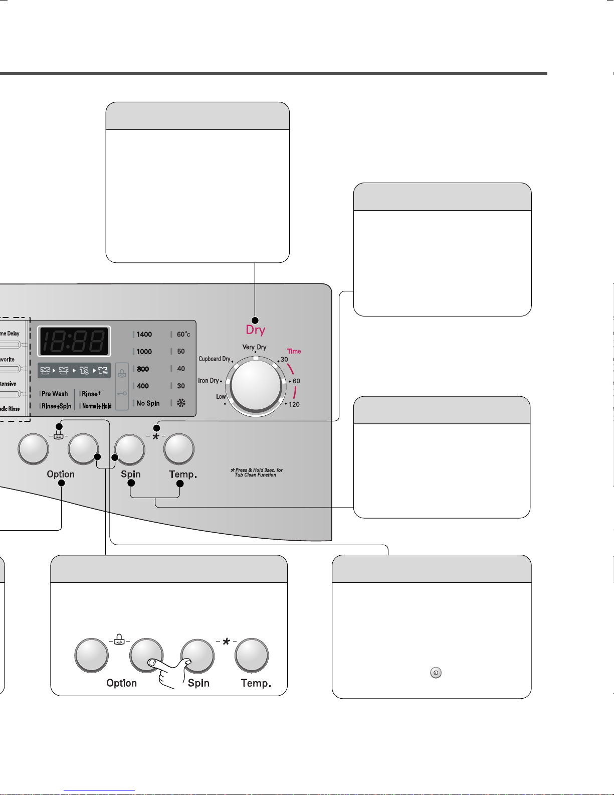
Dry Selector knob
• Dry programs selected by rotating
dry knob.
• [Lower Temp. - Iron Dry - Cupboard
Dry - Eco Dry - Time(30,60,120)]
can be selected.
Tub Clean
•Tub Clean course can be set by
pressing and holding Intensive and
Pre Wash button simultaneously.
•Tub Clean is special cycle to clean
the inside of the washer.
Beep on/off
• The Beep on/off function can be set by pressing
and holding the Option and Spin button
simultaneouly.
Spin,Temp. Button
•To change the spin speed,
Press the Spin button to cycle
through available options.
• Select a water termperature
based on the type of load you
are washing.
Child Lock
• Use this option to prevent unwanted
use of the washer. Press and hold
2 Option buttons for 3 seconds to
lock/unlock control.
• When Child lock is set, CHILD LOCK
lights and all buttons are disabled
except the Power button. You can
lock the washer while it is operating.
13
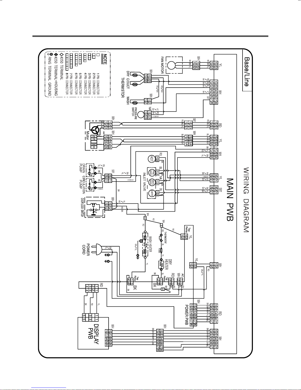
6.
WIRING DIAGRAM / PCB LAYOUT / PROGRAM CHART
14
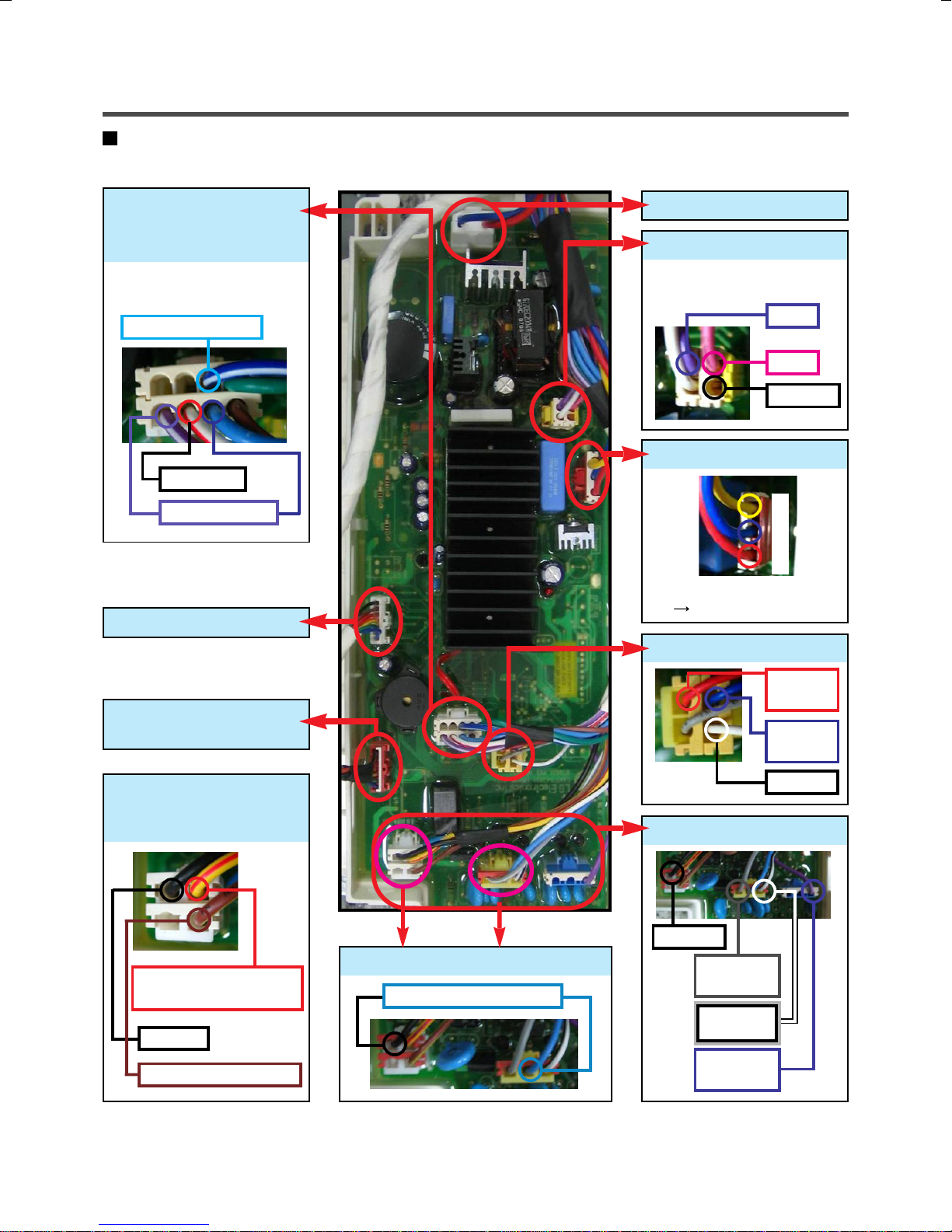
PCB Layout (Main)
Pressure Switch
&
Thermistor
Measure Hz impossible Here.
Just check cut-off.
Thermistor for Wash
Common
Pressure Switch
LCD DisplayLCD DisplayLCD Display
LCD DisplayLCD DisplayPCB Power
LCD DisplayLCD DisplayAG Sensor
Measure R impossible here.
Just check cut-off.
Long
Short
CommonCommon
LCD DisplayLCD DisplayMotor Stator Control
W
U
V
V ~ U / U ~ W / W ~ V
R : 8 ~11Ω
LCD DisplayLCD DisplayHall Sensor Control
LCD DisplayLCD DisplayHeater
(Next Page)
Door Switch
&
Drain Pump
Door Switch
Measure R impossible here
Common
Drain Pump (152~176Ω)
LCD DisplayLCD DisplayCirculation Pump
Circulation Pump (152~176Ω)
Ha
(5~15 kΩ)
Hb
(5~15 kΩ)
Common
Inlet Valve Control
Common
Pre. Valve
(3.5~4.5 kΩ)
Main Valve
(3.5~4.5 kΩ)
AG Valve
(3.5~4.5 kΩ)
15
 Loading...