

LG WD-1070FD Service Manual
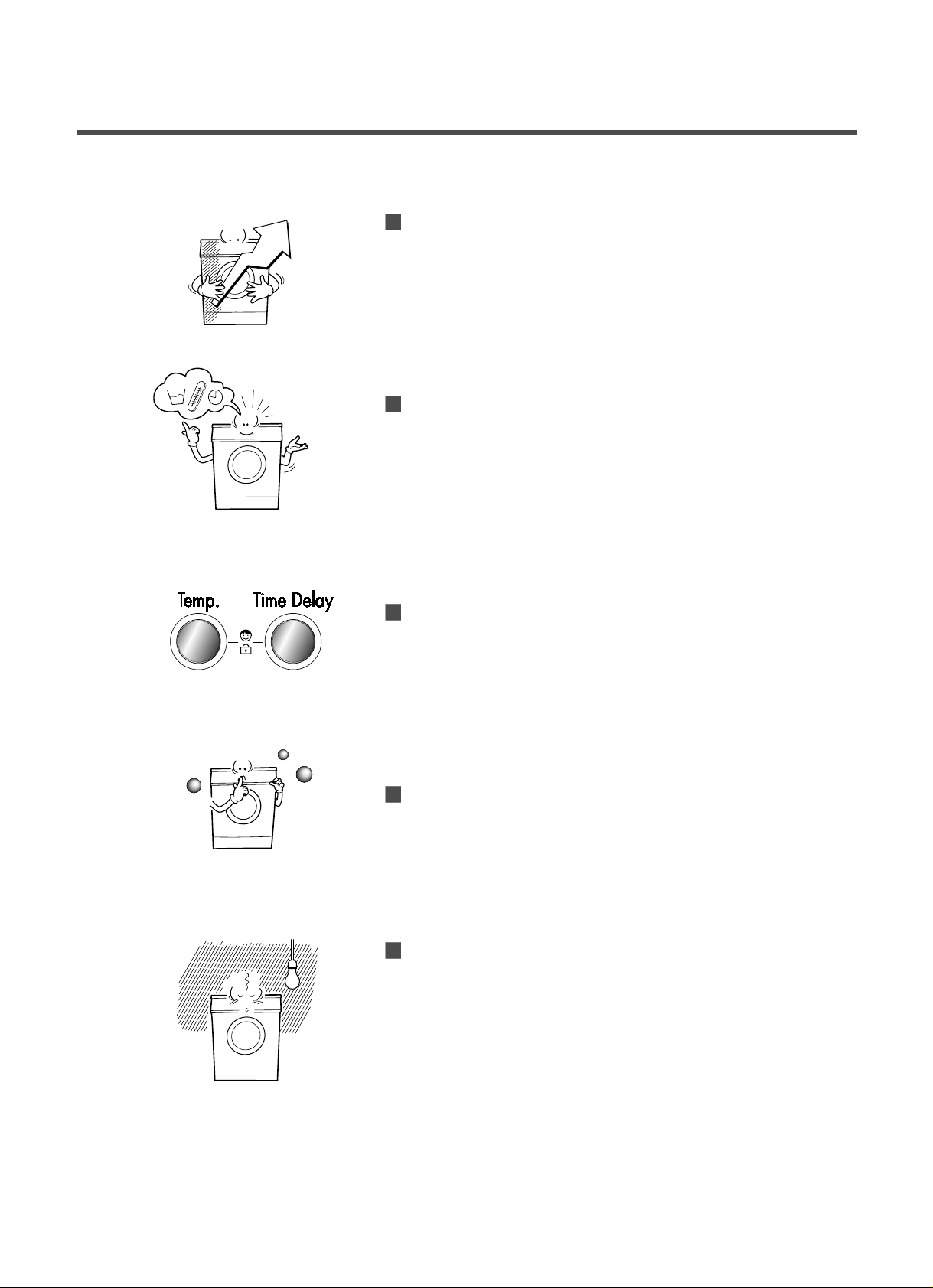
Jumbo drum
LG’s jumbo drum can wash about 40% more per load than
conventional washing machine. A bigger durm improves the
wash performance.
More economical by Fuzzy Logic System
FUZZY Logic System detects the amount of load and water
temperature, and then determines the optimum water level
and washing time to minimize energy and water
consumption.
Child-Lock
The Child-Lock system has been developed to prevent
children from pressing any button to change the programme
during operation.
Low noise speed control system
By sensing the amount of load and balance, evenly
distributes load to minimize the spinning noise level.
Auto Restart
Although the washing machine is turned off by a power failure,
it restarts automatically in its stopped process when power is
supplied again. and it will be the same when the machine
unplugged in operation is plugged in again.
2. FEATURES & TECHNICAL EXPLANATION
4
2-1.FEATURES
40%
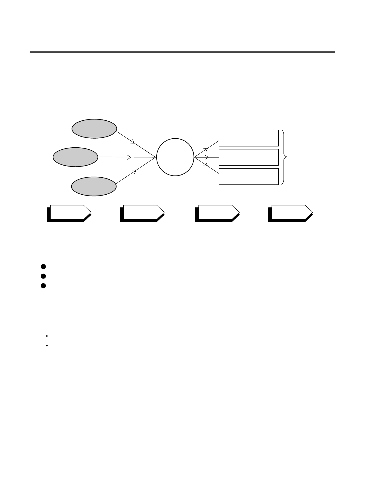
2-2.DETERMINE WASHING TIME BY FUZZY LOGIC
To get the best washing performance optimal time is determined by sensing of water temperature,
selected washing temperature and laundry amount.
2-3.WATER LEVEL CONTROL
This model adopts a pressure sensor which can sense the water level in the tub.
When the water level reaches to the preset level water supply is stopped, then washing program proceeds.
Spinning does not proceed until the water in the tub reduces to a certain level.
2-4.THE DOOR CAN NOT BE OPENED
While program is operating.
While Door Lock light turns on.
5
FUZZY
LOGIC
laundry
amount
selected
washing
temperature
water
temperature
washing time
rinse time
spin rhythm, time
the best
washing
performance
SENSING
PROCESSING
DETERMINA TION
EFFECT
Before servicing ask troubles of customers
Check the adjustment(power supply is 220-240V, remove the transit bolts....)
Check the troubles referring to the trouble shooting.
Decide service steps referring to disassembly instructions.
And then, service and repair .
After servicing, operate the appliance whether it works OKor NOT.
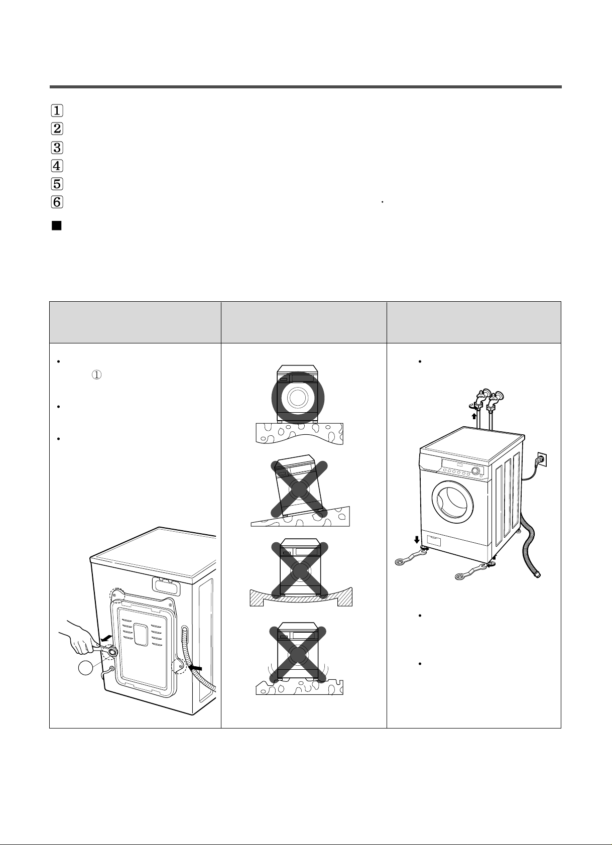
ST ANDARD INSTALLATION
The appliance should be installed as follows.
REMOVE THE TRANSIT INST ALL THE APPLIANCE ADJUST THE
BOL TS
ON FLA T AND FIRM SURFACE HORIZONT AL
Remove the transit bolts Turn the leveling feet to
(4EA:
)with supplied spanner. set the appliance horizontally .
Keep the transit bolts and
spanner for future use.
Insert the 4 caps provided
into the hole.
The appliance goes up by
rotating the feet clockwise.
The appliance come down by
rotating the feet counter
clockwise.
4. INSTALLATION
7
1
High
Low
HOW TO CONNECT INLET HOSE
Check that the rubber packing is inside of the
valve connector.
Connect the inlet hose firmly to prevent leak.
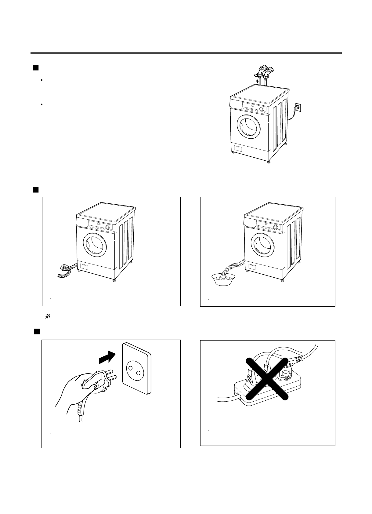
CONNECT DRAIN HOSE
CONNECT POWER PLUG
8
Make sure that the hose is not twisted.
The drain hose should be placed under 100cm from the floor.
Connect the power plug to the wall outlet.
Avoid connecting several electric devices,
It may be the cause of the fire.
Avoid submerging the end of the hose.
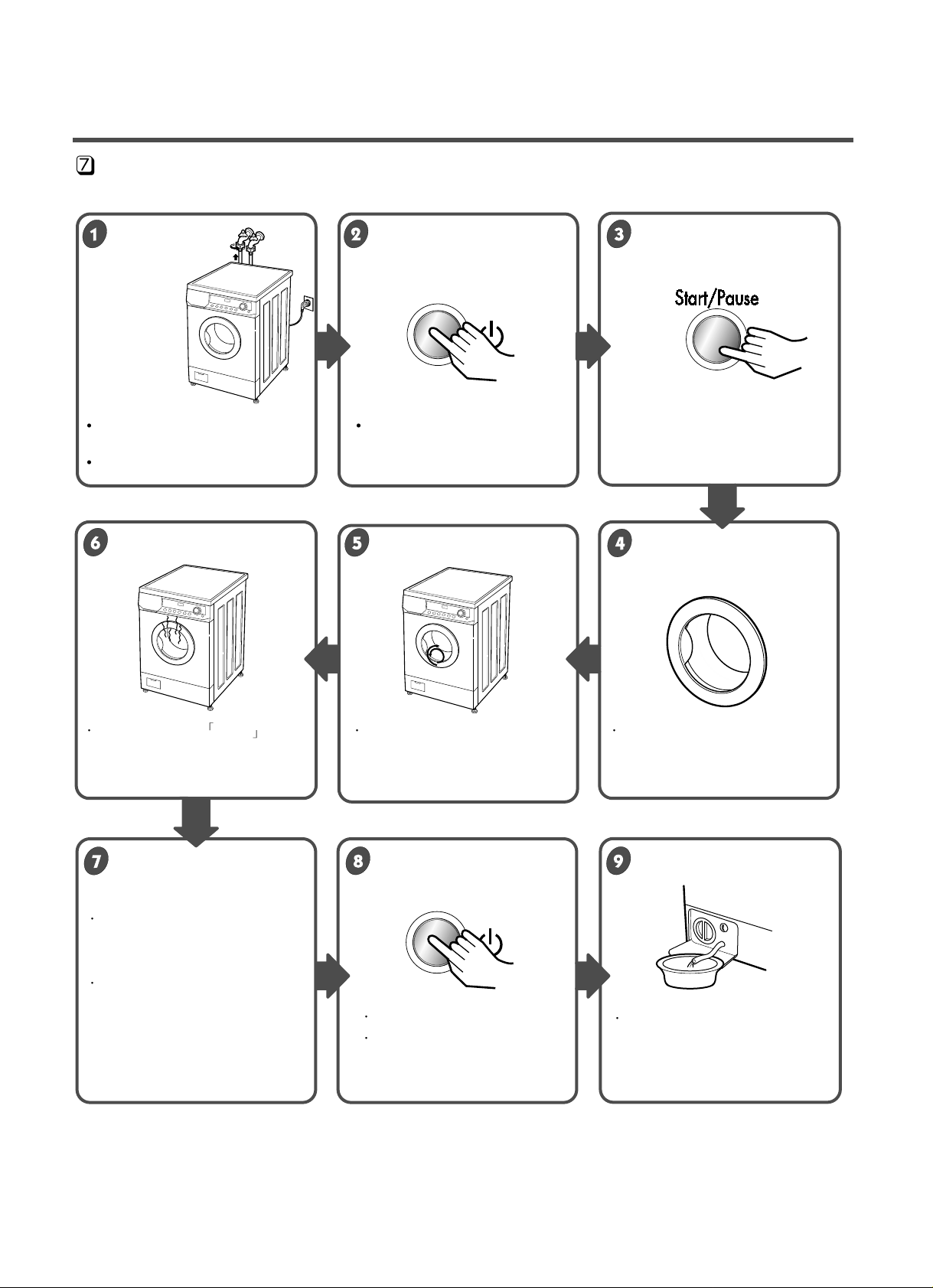
TEST OPERA TION
9
Connect the power plug to In case of Coloureds program.
the outlet.
Connect the inlet hose.
Preparation for Press the power button. Press
the
ST AR T/PAUSE
washing. button.
Press the button TEMP Check if the drum rotates Check if water is supplied
and the present temperature will
clockwise and counterclockwise.
through the detergent dispenser.
be displayed.
Power off and then power on.
Check if the door can be
opened after Door Lock lamp
turns off.
Turn off Spin and Temp after
pressing the Start/Pause button
and start the machine again.
Check drain and Spin.
If SVC is needed during
check, remove
the remaining water by pulling
out the hose cap.
Check the water heating. Check automatic reverse Check the water supply .
turn.
Check drain and spin
Power off and open the
Water removal
door
12
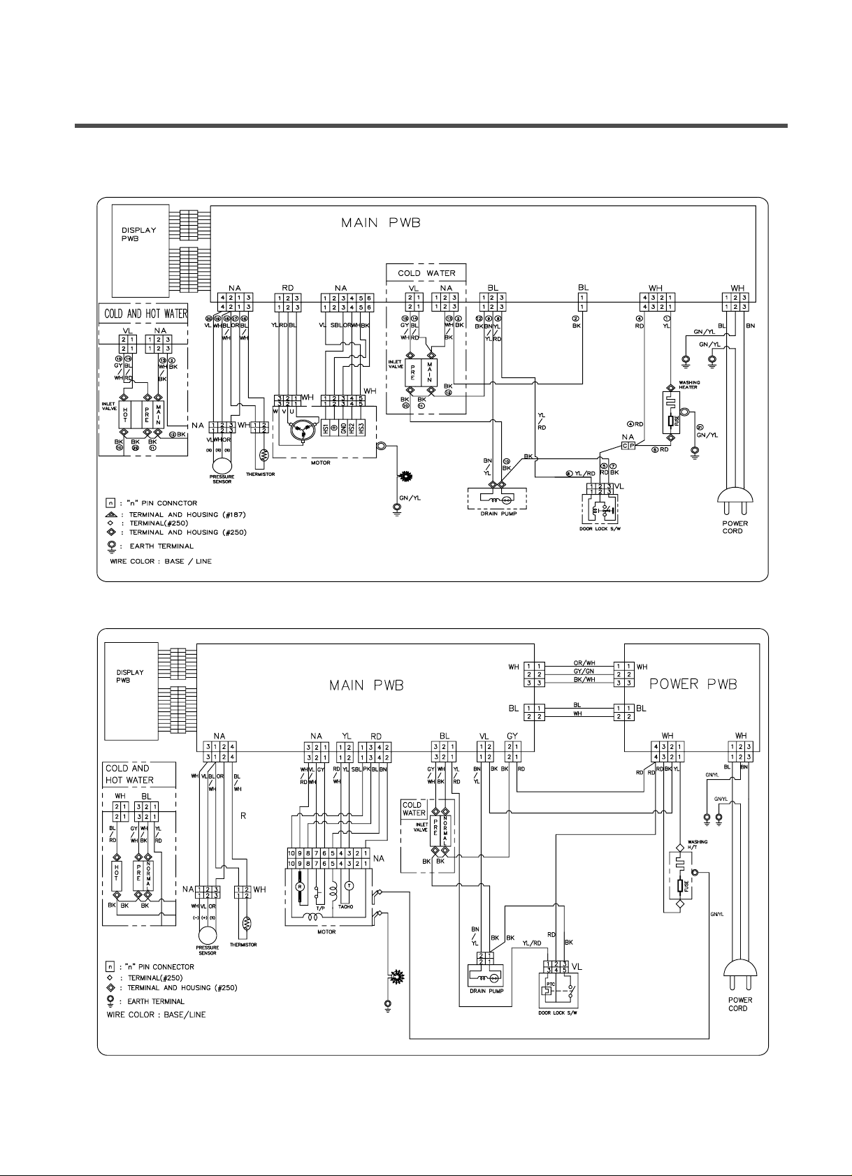
6. WIRING DIAGRAM
(option)
GN/YL
■ WD(M)-8070F(H)B, WD(M)-1070(5)F(H)B, WD(M)-1170(5)F(H)B, WD(M)-1270(5)F(H)B, WD(M)-1370(5)F(H)B
■ WD-8070F(H), WD-1070(5)F(H)
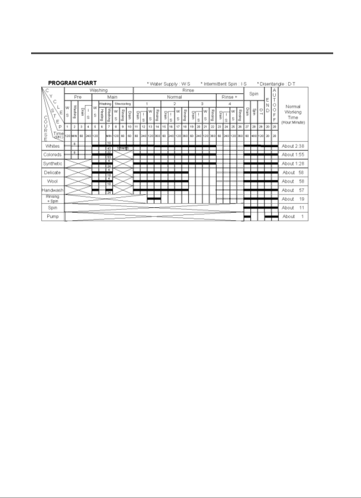
❋
Pre Wash : If the laundry is heavily soiled, “Pre Wash” course is effective. Pre Wash is available in Coloureds, Whites and
Synthetic Program.
❋
Eco : By selecting Eco function, the water temperature is reduced and washing time is lengthened. So you can economize in your
consumption of energy.
❋
Rinse+ : If you wish to rinse more, the Rinse+ function will remove any trace of detergents.
❋
Bio : If you want to elimenate protein stains (milk, blood, chocolate...), you may select Bio function by pressing the option button.
❋
You can select Bio function and Eco function when temperature is higher than
60˚C
in Whites, Coloureds and Synthetic.
13
7. PROGRAM CHART
8-1. BEFORE SVC CHECKING
¡ÆBe careful of electric shock or disconnecting the parts while trouble shooting.
¡ÆVoltage of each terminal in 220-240V~ and DC while applying an electric current.
8-2. QC TEST MODE.
¤ Pressing Spin, and Temp button simultaneously.
¤ŁPower supply ON with pressing upper two button. then buzzer sound twice.
¤ØPress the START/PAUSE button as follows.
¡aPress the ST ART/PAUSE button more 4 times until stop spinning¡b
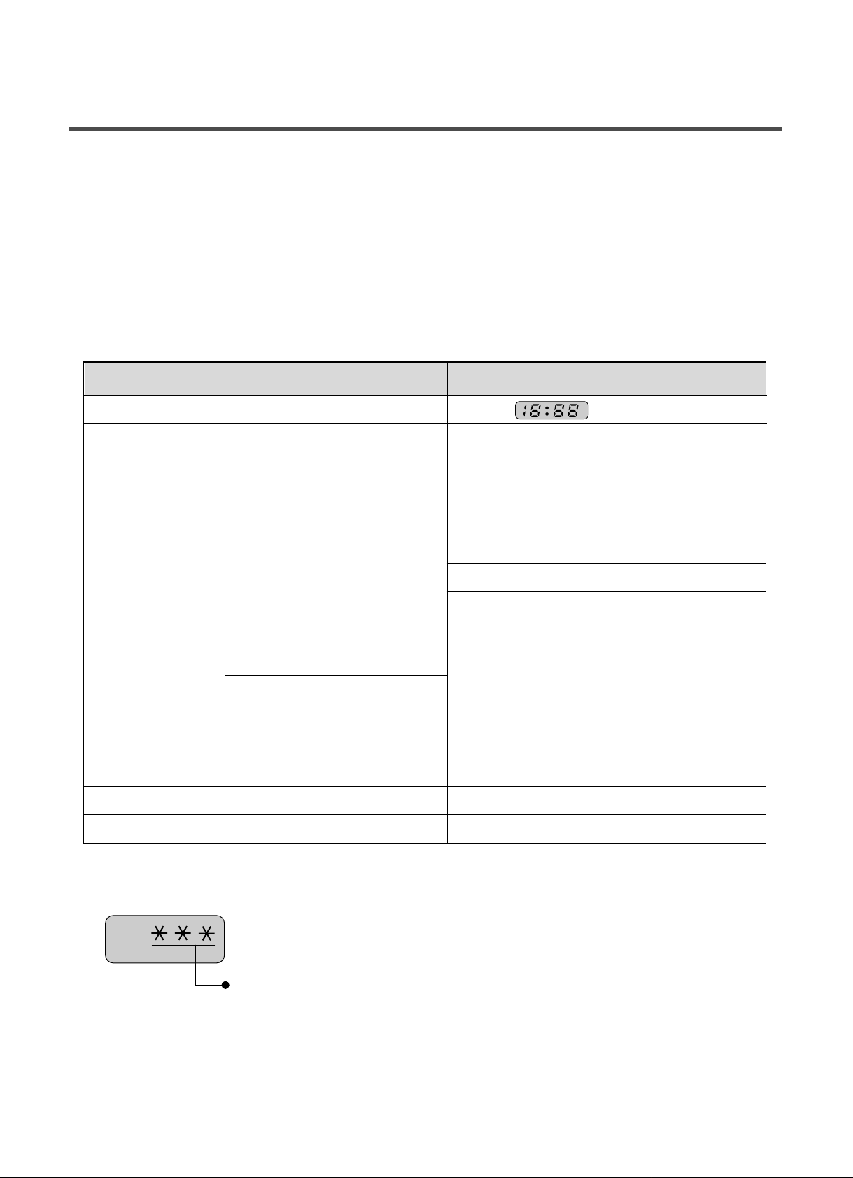
8-3. HOW TO KNOW THE W ATER LEVEL FREQUENCY
ƒRPress the
Option and Spin button simultaneously .
ex) 241 : Water level frequency = 241¡¿10-1§
=24.1§
14
8. TROUBLE SHOOTING
The digits means water level frequency(10
-1
§
)
Pressing number of
£ START/PAUSE£ button
Checking Point Display Status
None All lamps turn on
1 time Clockwise spin(right) Motor rpm(About 45)
2 times Low speed Spin Motor rpm(About 63~67)
3 times High speed Spin Motor rpm(About 79~85) : WD(M)-8070F(H)(B)
Motor rpm(About 100~106) : WD(M)-1070(5)F(H)(B)
Motor rpm(About 107~103) : WD(M)-1 170(5)F(H)B
Motor rpm(About 1 14~120) : WD(M)-1270(5)F(H)B
Motor rpm(About 122~127) : WD(M)-1370(5)F(H)B
4 times Inlet valve for pre-wash operation Water level frequency(25~65)
5 times
Inlet valve for main-wash operation
Water level frequency(25~65)
Hot inlet valve in case of hot water fill
6 times Inlet valve for main-wash operation Water level frequency(25~65)
7 times Counterclockwise spin(left) Motor rpm(About 45)
8 times A Heater is in operation for 3 sec. W ater Temperature
9 times Draining pump operation Water level frequency
10 times Auto off operation
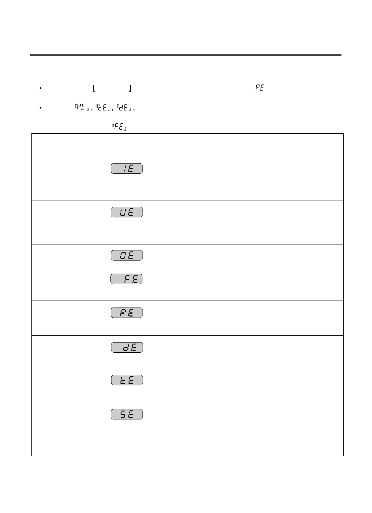
8-4. ERROR DISPLAY.
If you press the Start/Pause button in error condition, any error except ‘’ will disappear and the
machine will change into pause status.
In case of if the error is not resolved within 20 sec., and in case of other errors, if
the error is not resolved within 4 min., power will be turned off automatically and the error only will be
blinked. But in case of
, power will not be turned off.
15
ERROR SYMPTOM
CCAAUUSSEE
1 WATER INLET § Water has not reached to the pre-set level within 4 min. since
ERROR inlet valve operated or water has not reached to the normal
level within 25 min.
2 IMBALANCE § The appliance is tilted.
ERROR § Laundry is gatherd to one side.
§ Non distributable things are put into the drum.
3 DRAIN ERROR § Water has not drained enough within 5 min.
4 OVER FLOW § Water is automatically being pumped out because too much
ERROR water is in the tub.
5
SENSOR PRESSURE
§ The sensor pressure switch is out of order.
S/W ERROR
6 DOOR OPEN § The
¡aStart/Pause¡b
button is pressed with the door open.
ERROR § The door switch is out of order.
7 HEATING
ERROR
§ The thermistor is out of order.
8 SENSOR § The connector (5pin, male, white) in the Wire Harness is not
ERROR connected to the connector (5 pin, female) of Hall Sensor in
the MOTOR.
ƒ_’ reconnect or repair the contact in the connector
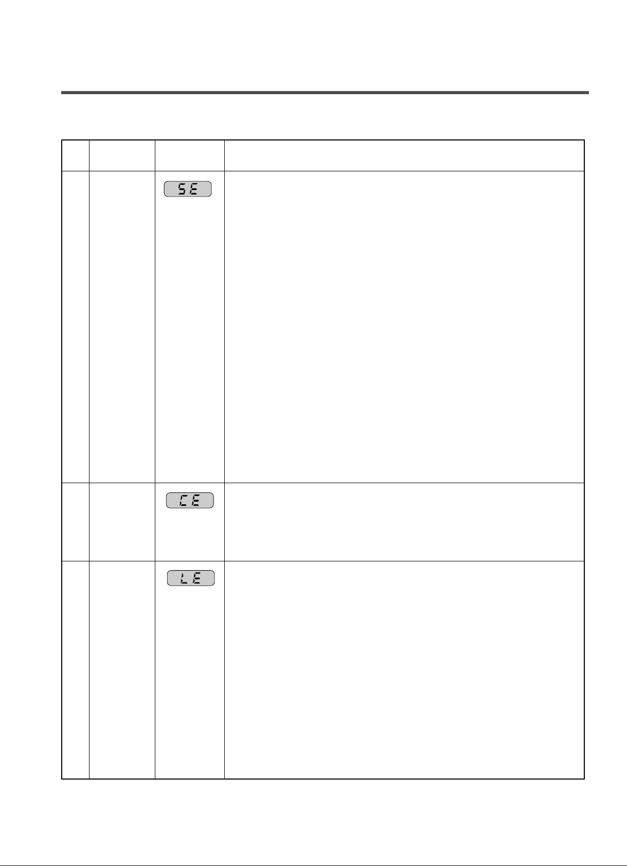
ERROR SYMPTOM CAUSE
8
9
10
• The electric contact between the connectors
(5 pin, male in the Wire Harness and 5 pin female in the Hall Sensor) is
bad or unstable.
ƒ_ Reconnect or repair the contact in the connector
• The connector (6 pin, male, natural) in the Wire Harness is not
connected to the connector (6 pin, female, natural) of PWB
ASSY(Main) or the electric contact of connectors is bad/unstable.
ƒ_ Reconnect or repair the contact in the connector
• The electric contact between the connectors ¡a6 pin, male in the Wire
Harness and 6 pin female in the controller(Main)¡bis bad or unstable.
ƒ_ Reconnect or repair the contact in the connector
• The Wire Harness between Hall Sensor in the MOTOR and PWB
ASSY(Main) is cut(open circuited).
ƒ_ Repair/replace the damaged WIRE HARNESS
• The Hall Sensor is out of order/defective.
ƒ_ Replace the Motor
• The controller(Main) is out of order/defective.
ƒ_ Replace the PWB ASSY(Main)
• PWB ASSY(Main) is out of order
ƒ_ Replace the PWB ASSY(Main)
• Winding in the MOTOR is short-circuited.
ƒ_ Replace the MOTOR
• The Connector(3 pin, male, white) in the Wire Harness is not
connected to the Connector(3 pin, female, white) of MOTOR.
ƒ_ Reconnect or repair the connector
• The electric contact between the connectors¡a3 pin, male, white in the
Wire Harness and 6 pin, female, white in the PWB ASSY(Main)¡bis bad
or unstable.
ƒ_ Reconnect or repair the contact in the connector
• The Wire Harness between the MOTOR and PWB ASSY(Main) is
cut(open circuited).
ƒ_ Repair the damaged(open-circuited) WIRE HARNESS
• The hall sensor is out of order/defective.
ƒ_ Replace the PWB ASSY(Main)
SENSOR
ERROR
CURRENT
ERROR
LOCK
ERROR
16
 Loading...