

LG G7020, W7020 Service Manual

7. STAND ALONE TEST AND TEST POINTS
7.1 Testing Set-up
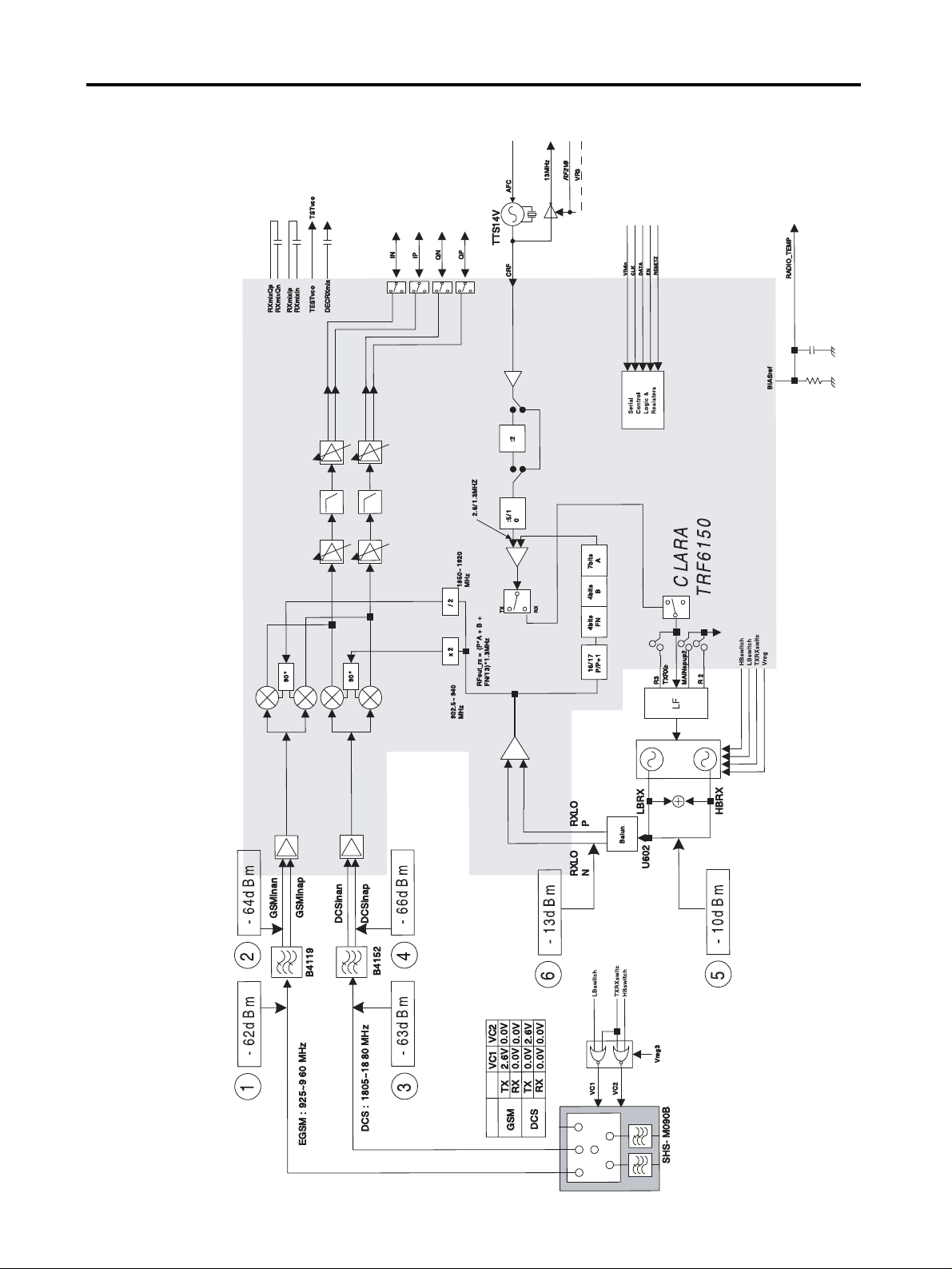
7.1.1 Received RF Level and Checks
This section shows the typical RF levels expected throughout the receiver path. A block diagram
showing the locations of the RF measurement points and levels is shown in Figure 7-3.
Receiver Testing Set-up
To check the receiver the following conditions have to be set:
1. On a signal generator or a GSM/DCS test box, output a CW signal of amplitude = -60 dBm at
either: 947.4 MHz (CH62) when testing the GSM RX path or 1842. 6 MHz (CH699) when testing
the DCS RX path.
2. Set the DC power supply to 4.0 V.
Note: All RF values shown are only intended as a guide figure and may differ from readings taken
with other test equipment and leads. Lead and connector losses should always be taken into
account when performing such RF measurements.
Testing Receiver
Using a suitable high frequency probe measure the RF levels at the relevant points shown in
Figure 7-2. and compares your measurements with those shown in the diagram. If there are any
major difference between the readings taken and those indicated then further investigation of that
particular point will be required. It will also be necessary to ensure that all the following power
supplies and signals are present which control this part of the receiver circuit:
1. The Control Signal of Antenna switch (see Figure 7-9,10,11 )
2. Vreg 1,2,3 (see Figure 7-7 )
3. 2V85_VCTCXO (see Figure 7-8)
4. 13MHz(see Figure 7-12)
5. CLK, DATA, EN (see Figure 7-13)
6. RX IP, IN, QP, QN (see Figure 7-16,19)
7. Vtune(see Figure 7-17,18)
7. STAND ALONE TEST AND TEST POINTS
- 62 -

7.1.2 Transmitted RF Level and Checks
This section shows the typical RF levels expected throughout the transmitter path. A block diagram
showing the locations of the RF measurement points and levels is shown in Figure 7-5.
Transmitter Testing Set-up
To check the transmitter the following conditions have to be set:
1. Configure the testing equipments as Figure equipment setup.
2. Set the GSM/DCS test equipment to be stand-alone mode (asynchronous mode).
3. Set the BCH and TCH ARFCN ‘62’ for EGSM900 or ‘700’ for DCS1800 on GSM/DCS test
equipment.
4. Set the DC power supply 4.0volts.
5. Initialize target on service software.
6. Set TCH and BCH value to be same with GSM/DCS test equipment on service software.
7. Select GSM or DCS mode on service software.
8. Set DAC ‘600’ for EGSM900 or ‘700’ for DCS1800 on service software.
9. Click Test.
Note: All RF values shown are only intended as a guide figure and may differ from readings taken
with other test equipment and leads. Lead and connector losses should always be taken into
account when performing such RF measurements.
Testing Transmitter
Using a suitable high frequency probe measure the RF levels at the relevant points shown in
Fig. 7-4 and compare your measurements with those shown in the diagram. If there are any major
difference between the readings taken and those indicated then further investigation of that
particular point will be required. It will also be necessary to ensure that all the following power
supplies and signals are present which control this part of the transmitter circuit:
1. The Control Signal of Antenna Switch(see Figure 7-9, 10, 11)
2. Vreg 1,2,3 (see Figure. 7-7)
3. 2V85_VTCXO (see Figure. 7-8)
4. 13 MHz (see Figure. 7-12)
5. PA_ON, PA_LEVEL, Vapc (see Figure. 7-14)
6. TX IP, IN, QP, QN (see Figure. 7-15)
7. STAND ALONE TEST AND TEST POINTS
- 63 -
7.2 Testing Points
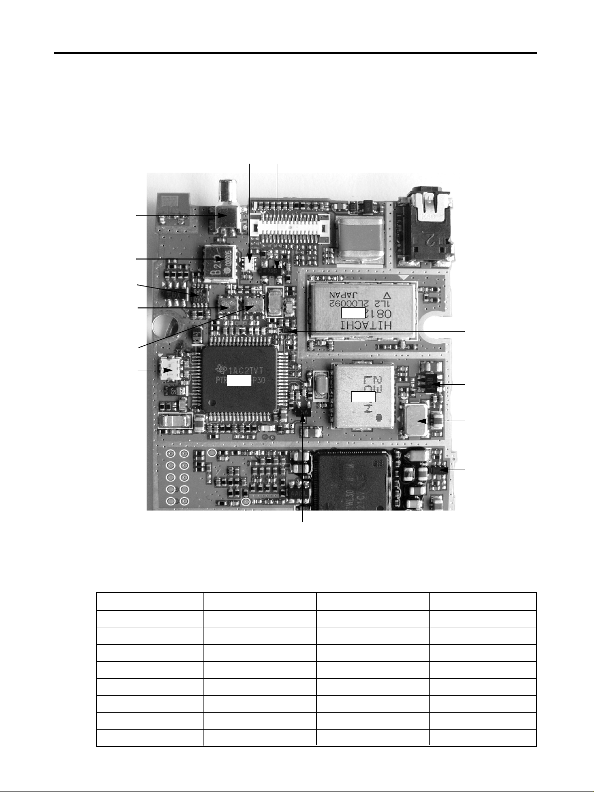
7.2.1 RF components (Component Side)
Figure 7-1. RF components (Component Side).
Table 7-1. RF components
7. STAND ALONE TEST AND TEST POINTS
Reference Reference
U604 RF main chipset U600 Dual RF VCO
U603 Antenna Switch U606 VCTCXO
U601 PAM U602 Balun
N600 Coupler BPF601 GSM RF SAW Filter
U607 NOR Gate BPF600 DCS RF SAW Filter
U629 Inverter SW600 Mobile Switch
U605 LDO D600 Dual Schottky Diode
D601 Varactor Diode D602 Varactor Diode
- 64 -
U604
U600
U601
SW600
N600 D600
D601
U605
U606
U629
D602
U603
U607
BPF600
BPF601
U602
7. STAND ALONE TEST AND TEST POINTS
- 65 -
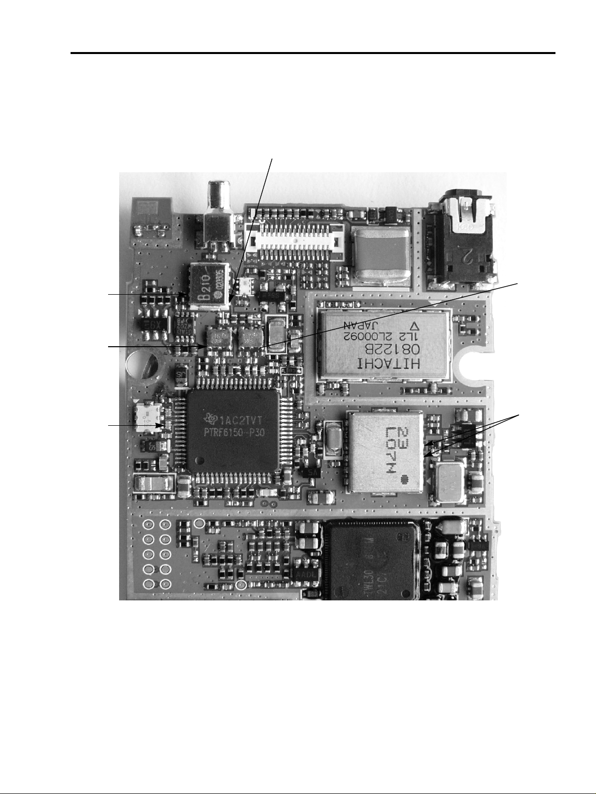
7.2.2 Test point of Rx Levels
Figure 7-2. Test point of Rx Levels.
1
6
4
3
2
5
2
7. STAND ALONE TEST AND TEST POINTS
- 66 -
GSM: CH.62, -60dBm
DCS: CH.699, -60dBm
Figure 7-3. Receiver RF Levels
 Loading...