

Page 1
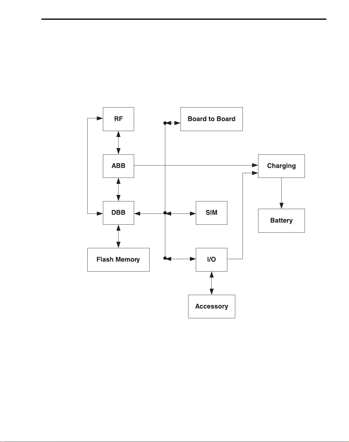
9. BLOCK DIAGRAM
9.1 Main Board
The G7000/W7000 is made up of two PCBs. In lower part of the folder, there is a main board. And
in the upper part of the folder, there is a FPCB. Below you can see the block diagram of both PCBs.
9. BLOCK DIAGRAM
Figure 9-1. Main Block diagram.
- 85 -
Page 2
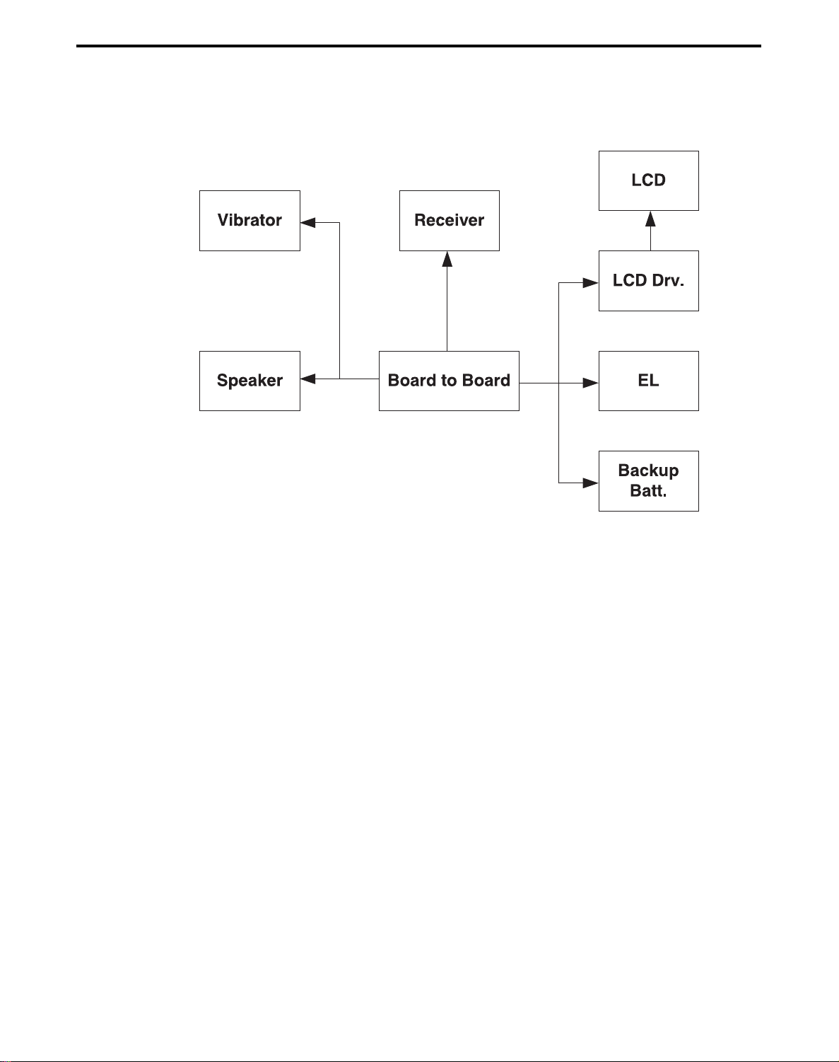
9. BLOCK DIAGRAM
9.2 FPCB
Figure 9-2. FPCB Block diagram.
- 86 -
Page 3
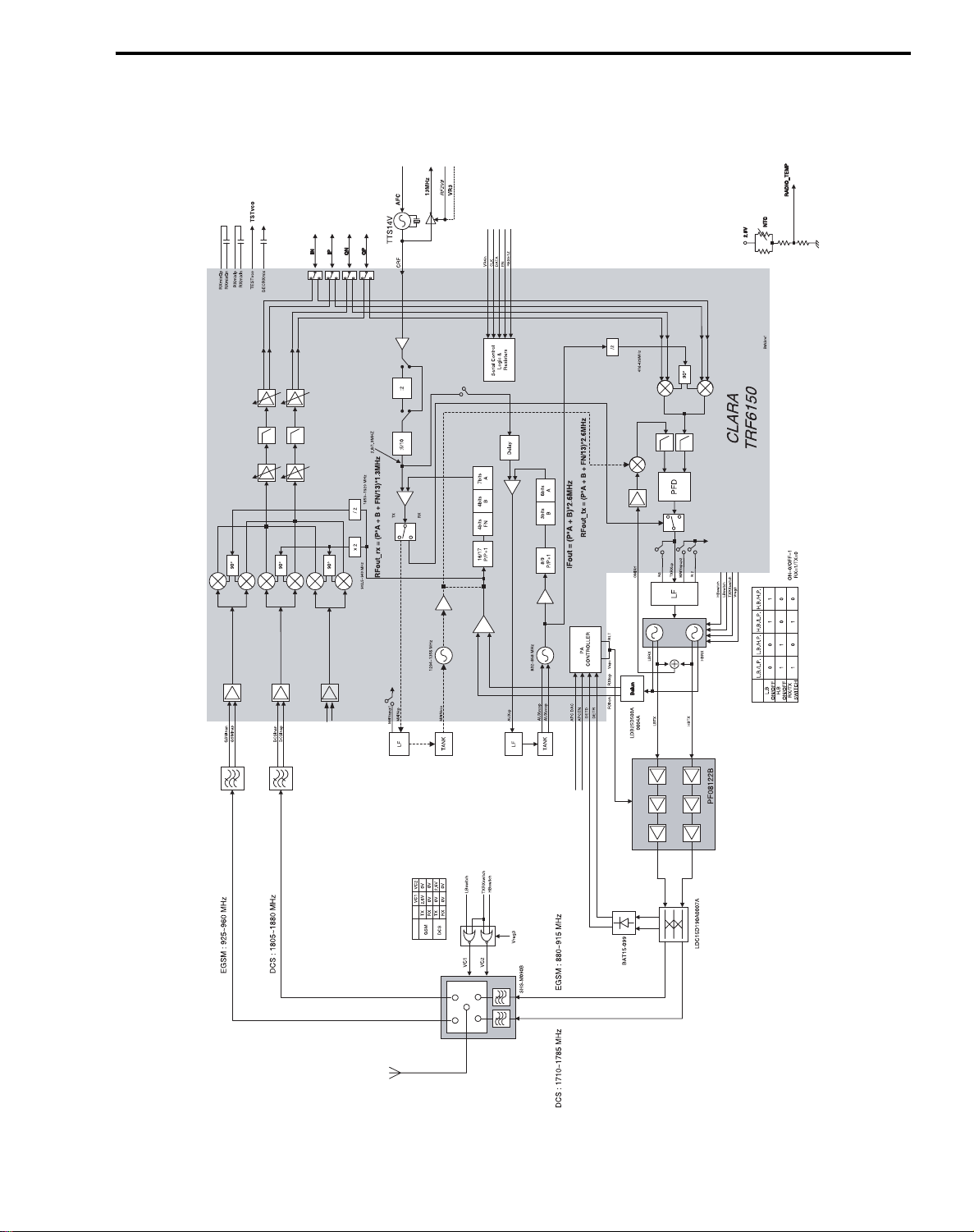
9.3 RF
9. BLOCK DIAGRAM
Figure 9-3. RF Block diagram
- 87 -
Page 4

9. BLOCK DIAGRAM
- 88 -
Page 5

10. CIRCUIT DIAGRAM
10.1 BB Circuit
A
LG_AMP_SIM
B
C
D
E
F
L
2
3
CLK
RST
J100
VPP
IO
6
7
27
26
VCHG2
VCHG1
BATT2
BATT1
AUXI
CTS
RTS
TX
TXD
AUXOP
AUXON
RXD
RX
DSR
HANDSFREE
POWER_ON
TDO
TMS
TCK
TDI
DCD
AUXGND
GND2
GND1
25
J101
LG-IO_CONN_24P
123
SIM_CLK
SIM_RST
SIM_I_O
1
VCC
GND
5
FOLDER
ON_OFF
HSP100
HSP101
HSP102
OUT
IN
Q101
RN1307
HSP103
GND
C109
100n/16V
(2012)
C103
150p
RPWRON
R100
20K
A(3)
MAIN_CS
SN74HC1GU04DCKR
U101
VR2B
R121
10K
U103
NC7SZ32
SIM_VDD
VR2B
R117
0R
5
2
4
3
VR2B
R120
0R
5
1
4
2
3
SUB_CS
VCHG
VBAT
BLM15AG100PN1
4
5
21
22
24
23
20
15
14
18
17
13
10
3
2
6
11
9
8
7
16
1
12
19
L100
BLM15AG100PN1
L102
HSP104
HSP106
HSP105
P0402FC12C
HSP107
V100
HSP108
HSP109
P0402FC12C
V101
R101
20K
HSP110
HSP112
HSP111
C105
47p
HSP113
HSP114
HSP116
HSP115
R103
MNR04
10K
HSP117
VR2B
HSP118
78
HSP119
123456
HSP120
HSP121
R104
10K
HSP122
C106
47p
C107
47p
R105
100R
R102
33K
1
4
VR2B
R118
10K
A(2)
R123
0R
R106
47R MNR04
2
4.7RR107
R108 4.7R
R110
47R
1K
R111
8
n.mR113 MNR04
1
34
56
78
12
34
56
78
12
34
56
7
12
34
56
78
MNR04
MNR04R112 47R
1
A0
2
B0
3
O0
4
A1
5
B1
6
O1
7
GND
MC74VHC126
BATT_TEMP
AUX_IN
CTS
RTS
TX
TXD
AUXOP
AUXON
RXD
RX
DTR
HANDSFREE
RPWRON
TDO
TMS
TCK
TDI
DCD
PCM_TX
PCM_SYNC
PCM_CLK
PCM_RX
U102
5
14
VCC
13
A2
12
B2
11
O2
10
A3
9
B3
8
O3
D(0:7)
MAIN_BACKLIGHT
SUB_BACKLIGHT
(REC_N)
5
VCHG
ICTL
_WR
LCD_RESET
I_LED1
I_LED2
I_LED3
SUB_CS
A(2)
MOTOR
EARN
REC_P
SPKN
SPKP
R124
0R
VR2B
_CS3
MAIN_CS
A(1)
D(0)
D(1)
D(2)
D(3)
D(4)
D(5)
D(6)
D(7)
L105
L106
L107
L108
L109
L110
L111
L112
L113
L114
L190
L124
L115
L116
L117
L118
L119
L120
R119
0R
R122
10K
R115
0R
6
C100
10u/16V
A_case
A(0)
MIDI_CS
L103
L104
BLM15AG121PN1
BLM15AG121PN1
BLM15AG121PN1
BLM15AG121PN1
BLM15AG121PN1
BLM15AG121PN1
BLM15AG121PN1
BLM15AG121PN1
BLM15AG121PN1
BLM15AG121PN1
BLM15AG121PN1
BLM15AG121PN1
BLM15AG121PN1
BLM15AG121PN1
BLM15AG121PN1
BLM15AG121PN1
BLM15AG121PN1
BLM15AG121PN1
HSP134
6234
HSP133
HSP135
HSP136
C101
22n
BLM15AG121PN1
BLM15AG121PN1
HSP131
HSP130
HSP137
HSP132
issue
456
3
12
D100
CRS08
R116
0.2R(1%)
(2012)
C104
10u
VCC_EXT
(2012)
R109
220R
HSP512
HSP127
HSP126
HSP128
Notice NO. Data Name
7
Q100
NDC652P
VBAT_2
VBAT
VBAT
C108
47p
Section
Designer
Checked
Approved
7
V102
P0402FC12C
R114
1M
VBACKUP
HSP514
HSP513
Date
02.04.11
02.04.11
LG
Electronics Inc
HSP129
LG_LCD_CON_30P
1
2
3
4
5
6
7
8
9
10
11
12
13
14
15
16
17
18
19
20
21
22
23
24
25
26
27
28
29
30
C110
1uF
(1608)
Sign & Name
D.S.JUNG
N.S.KIM
J102
VDD_3.0V
MAIN_CS
(D/I)
A0
D0
D1
D2
D3
D4
D5
D6
D7
_WR
_RES
VSS
LED_EN
VBACKUP
I_LED1
I_LED2
I_LED3
EL_EN
VBAT
SUB_CS
(A2)
CS2
VSS1
VBAT1
MOTOR
RECREC+
SPKSPK+
Model
Drawing
BASEBAND INTERFACE
Name
Drawing
No.
8
A
B
C
D
E
Sheet/Sheets
F
1/6
8
- 89 -
Page 6

10. CIRCUIT DIAGRAM
12 8910
KEYLIGHT
LCD_RESET
JACK_DETECT
SUB_BACKLIGHT
MELODY_INT
A
SUB_LED2
SUB_LED3
SUB_LED1
MELODY_RESET
PCM_CLK
PCM_SYNC
B
RXIR_IRDA
TXIR_IRDA
FOLDER
XO_ENA
RF_ENA
PCM_RX
PCM_TX
SD_IRDA
PWT
DTR
DCD
CTS
RXD
RTS
TXD
RX
TX
0RR231
C
J14
TP214
H11
H13
H12
H14
G12
M12
M14
L12
L13
J10
K11
K13
K12
K14
J11
J12
J13
B7
D7
E7
D6
A6
C6
E6
C5
B5
D5
E5
B4
C4
D4
A3
B3
F3
F2
G5
G4
G2
G3
H1
H3
H2
H4
H5
J1
J2
J3
J4
K3
K2
K4
J5
L1
L2
L3
D2
TSPCLKX
TSPDO
TSPEN0
TSPEN1
TSPEN2
nSCS2_TSPEN3
TSPACT00
TSPACT01
TSPACT02
TSPACT03
TSPACT04
TSPACT05
TSPACT06
TSPACT07
TSPACT08
TSPACT09
TSPACT10
TSPACT11
DATA00
DATA01
DATA02
DATA03
DATA04
DATA05
DATA06
DATA07
DATA08
DATA09
DATA10
DATA11
DATA12
DATA13
DATA14
DATA15
ADD00
ADD01
ADD02
ADD03
ADD04
ADD05
ADD06
ADD07
ADD08
ADD09
ADD10
ADD11
ADD12
ADD13
ADD14
ADD15
ADD16
ADD17
ADD18
ADD19
ADD20
ADD21
ADD22
0RR227
0RR228
CLK
DATA
EN
RESET_RF
PA_ON
D
TP208
D(0:15)
D(0)
D(1)
D(2)
D(3)
D(4)
D(5)
D(6)
D(7)
D(8)
D(9)
D(10)
D(11)
D(12)
TP210
TP211
TP212
D(13)
D(14)
D(15)
A(0)
A(1)
A(2)
A(3)
A(4)
A(5)
A(6)
A(7)
A(8)
A(9)
A(10)
A(11)
A(12)
A(13)
A(14)
A(15)
A(16)
A(17)
A(18)
A(19)
A(20)
A(21)
A(22)
TP213
E
A(0:22)
F
TP209
_WR
_RD
G
_CS3
_CS2
_CS1
_CS0
_BLE
_BHE
FDP
KBC(0:4)
KBR(0:4)
RnW_
B2
TP221
nFOE_X_A3
E2
nCS3_
D3
K8
M9
SDI_SDA
SDO_INT10n
nCS1_
nCS2_
C3
C1
3
L9
P9
NSCS0_SCL
SCLK_INT1n
nCS0_
C2
TP222
N9
NSCS1_X_A2
nBLE_I_O15
F5
E4
C8
TX_IRDA
nBHE_I_O14
nFWE_X_A0
FDP_nIACK
F4
E3
FWE
D8
A8
B8
B9
C7
RX_IRDA
X_A1RXIR_IRDA
X_A4_TXIR_IRDA
CLKOUT_DSP_SD_IRDA
KBC0_NFIQN4KBC1_NIRQK5KBC2_XD1_00
KBC3_XD1_01
KBC4_XD1_02
L5
P5
M5
KBC(0)
KBC(1)
KBC(2)
KBC(3)
KBC(4)
4 6
5
TP220
VR2B
R222n.m
10K R223
L4
E8
A9
C9
D9
TX_MODEM
RX_MODEM
CTS_MODEM_XF
DSR_MODEM_LPG
RTS_MODEM_TOUT
K9
L10
N10
M10
TXD_MCSI_1_09
RXD_MCSI_1_010
FSYNCH_MCSI_1_012
CLK_MCSI_1_011
N1
A13
A12
TCXOEN
RFEN_NoPC
niBOOT
P3
N3
M4
I_O2_IRQ4
I_O0_TPU_WAIT
I_001_TPU_IDLE
N11
H10
TSPDI_I_O4
BCLKX_I_O6
I_O3_SIM_RnW
N2
M2
P11
IDDQ
ARMCLK_BCLKR
I_O7_NRESET_OUT
U200
CALYPSO
XD1_03_KBR0
XD1_04_KBR1
XD1_05_KBR2
K6
P6
M6
KBR(0)
KBR(1)
KBR(2)
XD1_07_KBR4
XD1_06_KBR3
L6
N6
KBR(3)
KBR(4)
A11
VDDS_2
C223
100n
A4
VDDS_MIF0
B6
VDDS_MIF1G1VDDS_MIF2D1VDDS_MIF3
L14
VDDS_1_1
VDDS_1_2
N5
VDD0
VDD1
VDD2
VDD3
A5
P7
B12
N14
C224
100n
GND2
GND3
C225
100n
GND0F1GND1
N8
GND4
K1
P2
P4
P10
VDD5
VDD4
E1
M1
C226
GND5
100n
7
VR2B
10KR672
VDD_RTC
C233
100p
C229
C204
D10
H10
100n
18p
F6
D7
F7
H4
F2
C8
B8
A9
B9
C7
A7
B7
A8
J5
K5
G5
H5
K7
G6
G7
H6
J6
K6
F5
B2
C4
B3
K3
D2
G9
K2
J1
H3
E2
D3
H1
E1
C1
D1
R201
220K
ON_OFF
RESPWRONZ
RTC_ALARM
INT1
INT2
TESTRESETZ
TEST1
TEST2
TEST3
TEST4
TDO
TDI
TCK
TMS
BFSX
BDX
BFSR
BDR
VDR
VDX
VFS
VCK
UDX
UDR
UEN
SDIO3
SCLK3
SRST3
VCC1
VCC2
VCC3
SWITCH
FDBK
RESERVED
VR2IN
VR2SEL
VR1OUT
VR2OUT
VR3OUT
VR1BOUT
VR2BOUT
UPR
VBAT
J4
K4
A10
F1
B10
TDR
PWON
OSCAS
RPWON
U201
NAUSICA_CS
GRND1
GRND2
GRND3
F3
K1
C2
G10
VBAT
A4
TEN
CK13M
ADIN4_TSCXP
ADIN5_TSCYP
REFGND
RPWRON
nBSCAN
LCDSYNC
TSCYM
TSCXM
ADIN1
ADIN2
ADIN3
DAC
AFC
APC
AUXGND
BDLQM
BDLQP
BDLIM
BDLIP
BULQM
BULQP
BULIM
BULIP
MICBIAS
AUXI
AGNDA1
MICIP
MICIN
EARP
EARN
AUXOP
AUXON
BUZZOP
VAUX
VS2
VS1
SVDD
SDIO5
SCLK5
SRST5
UPR
VBACKUP
VBAT
VCHG
ICTL
BGTR1
BGTR2
BGTR3
BGTR4
BGTR5
IBIAS
VREF
TDI
TDO_ARM
C5
A6
B6
B5
A5
E6
D6
C6
F10
F8
F9
G8
E10
E9
E8
E7
D9
D8
C10
C9
K9
H7
J7
K8
J8
H9
H8
J9
J10
K10
A3
A1
B1
A2
D4
B4
D5
C3
J3
E5
E4
E3
G4
G3
G2
H2
J2
G1
F4
UPR
C232
33u/6.3V
A-CASE
VBAT_2
UPR
C228
100n
R220
10K
C202
C203
20P
R224
0R
INT4n_IT_WAKEUP
MCUEN1_I_O8
MCUEN2_I_O13
SIM_CD_MAS0
SIM_PWCTRL_I_O5
VDD_PLL
GND_ANG
GND_PLL
F11
E14
CLKTCXO
ON_OFF
nRESPWON
EXT_FIQ
EXT_IRQ
NEMU0_
NEMU1_
NBSCAN_
VFSRX
VCLKRX
MCUDI
MCUDO
MCUEN0
SIM_IO
SIM_CLK
SIM_RST
N.C
C11
C234
10u
(2012)
R221
n.m
E13
F12
TP218
TP217
TP216
F10
D12
B14
P1
M3
B11
E10
D11
D10
TDI
C10
TDO
B10
TCK
E9
TMS
L11
BFSR
K10
BDR
P12
BFSX
M11
BDX
P14
VDX
N13
VDR
M13
N12
N7
M7
M8
P8
L8
G13
F13
G10
G11
F14
R208
20K
VDD_RTC
D202
1SS388
TP204
SPK_EN
VR2B
VR1
VR2B
V1B
C222
2.2u
(2012)
TP205
VR3
C219
(2012)
VBACKUP
TP206
R225
1M
D201
1SS388
R209
1M
R211
C221
(2012)
20K
10u
VR2
C220
10u
10u
(2012)
20P
X200
MC-146
4
1
3
2
L7
K7
GND6
P13
G14
PWT_BU
GND7
R229
B13
A14
C13
C12
VSSO
PWL_LTGND8
OSC32K_IN
CLK32K_OUT
OSC32K_OUT
START_BIT_CLK13M_OUT
GND10
GND11
VDDS_RTC
VDD_ANG
VDD_RTC
GND9
GND_RTC
A2
B1
A7
A10
E11
E12
D13
D14
C14
0R
C227
100n
H
1
23
4
56
7
89
10 11
C218
100n
TMS
issue
TCK
TDO
1nC205
R204 390R
R205 390R
R206 390R
C215
220n
VBATUPR
Notice NO.
GND
C216
100nC217
R219
120K
_WR
390RR207
Data
(1608)
1u
Name
D200
1SS388
11
UPR
UPR
R203
R202
10K
10K
_WR
TP219
33n
C206
R281 0R
R282 0R
C213
270p
C211
270p
VBACKUP
R226
n.m
VDD_RTC
C231
100n
Section Date Sign & Name
02.04.11
Designer
Checked
02.04.11
Approved
LG
Electronics Inc
D.S.JUNG
N.S.KIM
0RR280
0RR283
U202
3
OUT
1
GND
Model
Drawing
Name
Drawing
No.
S-817
IN
NC
12
ON_OFF
TDI
TMS
TCK
TDO
HANDSFREE
END_ON_OFF
RPWRON
13MHZ
MCLK
BATT_TEMP
RADIO_TEMP
HOOK_DETECT
AFC
PA_LEVEL
QN
QP
IN
IP
MICBIAS
AUXI
MICIP
MICIN
EARP
EARN
AUXOP
AUXON
SIM_VDD
SIM_I_O
SIM_CLK
SIM_RST
VCHG
ICTL
VBACKUP
2
4
C230
100n
Sheet/Sheets
2/6
BASEBAND CHIPSET
12
A
B
C
D
E
F
G
H
- 90 -
Page 7

10. CIRCUIT DIAGRAM
1 52
43
6
A
VR2
VR2
B
78
D(0:15)
A
B
A(1:22)
TP301
A(1)
A(2)
A(3)
A(4)
A(5)
A(6)
A(7)
A(8)
C
R302
_CS1
A(9)
A(10)
A(11)
A(12)
A(13)
A(14)
A(15)
A(16)
A(17)
A(18)
A(19)
A(20)
A(21)
A(22)
0R
D
G2
A0
F2
A1
E2
A2
C2
A3
D2
A4
F3
A5
E3
A6
C3
A7
D6
A8
C6
A9
E6
A10
F6
A11
D7
A12
C7
A13
E7
A14
F7
A15
G7
A16
D3
A17
E4
A18
F5
A19
F4
A20
E5
A21
H2
CE_
J2
OE_
C5
WE_
H7
BYTE_
C4
RY_BY_
D4
WP_
D5
RESET_
U302
TC58FVB641
DQ0
DQ1
DQ2
DQ3
DQ4
DQ5
DQ6
DQ7
DQ8
DQ9
DQ10
DQ11
DQ12
DQ13
DQ14
DQ15
VDD
VSS0
VSS1
NC0
NC1
NC2
NC3
NC4
NC5
NC6
NC7
NC8
NC9
NC10
NC11
NC12
NC13
NC14
G3
K3
G4
K4
K5
G5
K6
G6
H3
J3
H4
J4
H5
J6
H6
J7
J5
K2
K7
A1
A2
A7
A8
B1
B7
B8
L1
L2
L7
L8
M1
M2
M7
M8
C300
100n
D(0)
D(1)
D(2)
D(3)
D(4)
D(5)
D(6)
D(7)
D(8)
D(9)
D(10)
D(11)
D(12)
D(13)
D(14)
D(15)
D(0)
D(1)
D(2)
D(3)
D(4)
D(5)
D(6)
D(7)
D(8)
D(9)
D(10)
D(11)
D(12)
D(13)
D(14)
D(15)
C301
J3
G4
K4
H5
H6
K7
G7
J8
K3
H4
J4
K5
J7
H7
K8
H8
J5
J6
K6
J9
G3
A1
A10
B1
B10
C1
F1
F10
G1
G10
L1
L10
M1
M10
U301
TH50VSF4683
DQ0
DQ1
DQ2
DQ3
DQ4
DQ5
DQ6
DQ7
DQ8
DQ9
DQ10
DQ11
DQ12
DQ13
DQ14
DQ15
VCCF
VCCS
DU_CIOS
VSS0
VSS1
NC0
NC1
NC2
BYTE_
NC3
NC4
RY_BY_
NC5
NC6
RESET_
NC7
NC8
NC9
NC10
CE1S_
NC11
CE2S_
NC12
R301 n.m
CEF_
OE_
WE_
WP_
UB_
G2
A0
F2
A1
E2
A2
D2
A3
F3
A4
E3
A5
D3
A6
C3
A7
C7
A8
E7
A9
F7
A10
C8
A11
D8
A12
E8
A13
F8
A14
D9
A15
G9
A16
F4
A17
E4
A18
D7
A19
E6
A20
E9
A21
H2
H3
C6
H9
E5
C5
D5
C4
LB_
D4
J2
D6
G8
DU
A(10)
A(11)
A(12)
A(13)
A(14)
A(15)
A(16)
A(17)
A(18)
A(19)
A(20)
A(21)
A(22)
R305
10K
A(1)
A(2)
A(3)
A(4)
A(5)
A(6)
A(7)
A(8)
A(9)
VR2
R300 0R
0RR303
_CS0
_RD
_WR
FDP
_BLE
_BHE
_CS2
C
D
C304
33n
100n
E
F
123 678
45
issue Notice NO. Data Name
Section Date Sign & Name
Designer
02.04.11
02.04.11
LG
Electronics Inc
D.S.JUNG
N.S.KIM
Checked
Approved
Model
Drawing
Name
Drawing
No.
Sheet/Sheets
MEMORY DEVICE
E
F
3/6
- 91 -
Page 8

10. CIRCUIT DIAGRAM
1
23 5
4
6
78
VR3
R400
1K
MICBIAS
A
C400
47p
C401
10u
(2012)
JACK_DETECT
2
56
4
1
3
U404
MAX4599
D401
KDS160E
R401
2.4K
C402
47p
A
MICIP
C405
47p
C403
n.m
C408
100n
C404
100n
C406
47p
C407
47p
HSP400
HSP401
MIC400
OB-22S40-C33
Microphone
MICIN
B
VR3
VR3
R404
VR3
U400
MAX9075
5
3
+
C
JACK_DETECT
1
4
-
2
18K
R405
1M
C409
47p
R407
1M
AUXI
AUX_IN
AUXOP
R420
HOOK_DETECT
C427
47p
100R
D
C416
220n
VBAT
R402
1.2K
C413
100n
1
2
3
4
C414
47p
U401
CNIOSE
DELAY ERROP_
GND
SENSE_ADJ
VIN VOUT
SI9182
R419
7.5K
R408
R409
R410
SD_
B
C410
33p
EARNEARN
Receiver
REC_P
C411
47p
C412
47p
HSP403
HSP402
C
J400
9001-8905-040
4.7R
4.7R
4.7R
HSP404
C415
47p
8
7
6
5
HSP405
HSP406
VCC_EXT
C417
2.2u
(2012)
V400
P0402FC05C
V401
P0402FC05C
2
4
3
1
Headset jack
D
VR3
ON_OFF
C420
R422
C419
10n
390p
n.m
D(5)
D(6)
D(2)
D(3)
D(4)
23
D126D225D324D4
U403
YMU762
NC
-IRQ3-RST
4
5
6
22
PLLC
R418
3.3K
C426
D(7)
21
20
19
D5
D6
D7
MTR
SPOUT2
SPOUT1
SPVSS
SPVDD
HPOUT-R
HPOUT-L
VDD
VREF
VSS
7
9
8
C424
100n
1n
R421
18
17
16
15
11
10
VR2B
C425
100n
D(0)
D(1)
27
D0
12
EQ1
13
EQ2
14
EQ3
28
WR_
29
_CS
30
A0
31
_RD
32
IOVDD
LED
CLK1
1
2
5
C418
2
+
-
31
6
4
U402
MAX4624
C421
18p
E
EARP
5
SPK_EN
R417
10K
F
1 34
2
22n
MELODY_INT
MELODY_RESET
R414
33K
R450
150K
MIDI_CS
SUB_LED1
_WR
_RD
MCLK
A(1)
R416
82K
R415
39K
C422
47p
6
D(0:7)
0R
HSP408
V402
P0402FC05C
issue
1
2
C423
47p
Notice NO.
VIBRATOR
V403
Data
HSP407
Speaker
1
2
SPKP
SPKN
E
P0402FC05C
F
4/6
Name
Section
Designer
Checked
Approved
Date
02.04.11
02.04.11
LG
Electronics Inc
Sign & Name
D.S.JUNG
N.S.KIM
Model
Drawing
Name
Drawing
No.
Sheet/Sheets
AUDIO
78
- 92 -
Page 9

10. CIRCUIT DIAGRAM
A
B
C
D
E
F
TXRXSW
HBSW
LBSW
VREG3
PA_LEVEL
PA_ON
CLK
DATA
VR2B
C661
2.2u
(2012)
RF_ENA
XO_ENA
VR3
AFC
13MHZ
RESET_RF
RADIO_TEMP
EN
QN
QP
C626
4.7u
P-CASE
48
47
46
45
44
43
42
41
40
39
38
37
36
35
34
33
C678
n.m
R634
R601
300R
R606
100R
L612
6.8N
R646
2.2K
C642
C646
C648
C657
5
C605
12p
C608
47p
100n
100n
100n
R638
2.2K(1%)
C698
100n
C637
39p
15p
2
AN1CAT
D601
HVC369B
TXRXSW
LBSW
HBSW
8
PIN_DCS
1
PIN_GSM
U601
PF08122B
1.2nC691
C671
12n
(3216)
R641
390R(1%)
VBAT
3
VDD16VDD2
VAPC7VCTL
2
L608
3.3N
R635
LB_LP
R649
10R
R624
620K
1K
1
1
GND110GND2
9
C662
3p
C603
POUT_DCS
POUT_GSM
C670
1.2n
C674
1n
(2012)
470u
C649
3p
L609
3.9N
LB_HP
0
0
1
C600
C601
47p
12p
5
C609
4
C611
1.5p
C643
7p
C645
7p
L605
18N
L606
18N
HB_LP HB_HP
1
10
0
6
L635
C612
n.m
C602
1n
4.7N
47p
L602
L603
0
1
0
issue
N600
LDC15D190A0007A
C610
C613
1.2p
n.m
R616
n.m
R622
120R
SAFSD1G84CB0T00R00
2.7N
2.7N
SAFSD942MCL0T00R00
3.3p
C658
3.3p
C660
TXRXSW
VREG3
Notice NO.
ANT_PAD_LGX
2345
67
R608
51R
C629
27P n.m
D600
BAT15-099
4
123
BPF600
6
12345
BPF601
6
12345
HBSW
LBSW
Data Name
ANT600
1
C630
7
8
Section
Designer
Checked
Approved
R609
0R
R623
n.m
L601
L632
3.3N
C639
n.m
L633
3.3N
C640
n.m
Date
02.04.11
02.04.11
LG
Electronics Inc
12n
R617
51R
L600
0R
C606
C690
0.5p
Sign & Name
n.m
Y.M.CHO
D.H.KIM
SW600
MHC-173
U607
NC7WZ02
1
2
3
4
C683
100n
Model
Drawing
Name
Drawing
No.
8
10
6
2
12
3456
DCS_TX
EGSM_TX
DCS_RX
EGSM_RX
C627
1n
R625
1K
867
8
7
6
5
8
C604
27p
VC17VC2
1
RF MAIN
U603
SHS-M090B
4
ANT
GND1
GND2
GND3
GND4
GND5
GND6
Sheet/Sheets
13
12
11
9
5
3
C628
1n
R626
1K
6/6
A
B
C
D
E
F
1
3
5
4
3
R673
270k
2
ENFVZ4L07
8
PWR_SW
9
DCS_SW
10
GSM_SW
11
VCC
12
GND3
13
VT
C619
1n
C636
33u/6.3V
A-CASE
R632
0R
C664
2.2u
(2012)
U606
VC-TCXO-208C
4
VCC
1
CTL
OUT
GND
2
2
U629
SN74HC1GU04DCKR
TP610
R674
680R
U600
GND414GND5
7
C623
R678
0R
3
C680
1n
R675
4.7k
H_H_PWR
GND2
H_L_PWR
L_L_PWR
GND1
L_H_PWR
100n
R679
n.m
C665
10n
C675
34
R600
18R
7
6
5
2.2K R615
33R R620
1.2K R621
55
56
57
VCC6
GNDTXCP
MAINSPUP2
AUXVCON
RXMIXQN
RXMIXQP
24
26
25
C666
1n
L611
6.8N
R648
D602
HVB387BWK
C632
4.7p
54
27
2.2K
R602
300R
C620
27p
27p C621
52
53
RXLOP
RXLON
RXMIXIN
RXMIXIP
28
29
C667
1n
2
C62227p
C633
100n
50
51
VCC4
VBAT1
OMIXRF
BIASREF
DECRXMIX
TESTVCO
31
30
C668
100n
C681
4.7p
A2
3
R605
R607
100R
VBAT
C635
4.7u
P-CASE
49
VREG1
VAPC
FILT
DETD
DETR
DCSLNAN
DCSLNAP
VCC3
PCSMIXN
PCSMIXP
GNDLNAN
VCC2
GSMLNAN
GSMLNAP
MAINVCO
VCC1
VCC8
BANDGAP
32
C669100n
1
CAT
68R
9.76K(1%)
C682
4.7p
A1
10pR603
R604 1K
6
5
4
3
2
1
VBAT
C624
2.2u
(2012)
U602
LDB32942M05D-429
8
2
4
C614
330p
R610
0R
C625
1n
(1608)
OUTN
DCS
NC2
GSM
OUTP
NC1
GND13GND2
1
C615
12n
(3216)
R619n.m
C634
100n
64
63
61
62
58
60
LB-SW
RESETZ
18QN19
17
VCC5
VBAT3
VREG3
IN
QP
20
59
R3
IP
21
22
R2
TXRXCP
U604
TRF6150
AUXVCOP
VCC7
23
C687
2.2u
(2012)
C638
C641
C647
C672
1.2n
(1608)
1n
R647
3.3N
C684
n.m
100n
100n
100n
10
11
12
13
14
15
16
R636
2.7K(1%)
C673
5.6n
(1608)
1
HB-SW
2
TXRX-SW
3
VCC10
4
MAINSPUP1
5
MAINCP
6
VBAT2
7
VREG2
8
APC
9
APCEN
VR4IN
CLK
DATA
EN
AUXCP
VCC9
CRF
C685
100n
1
C692 1n
R656 1K
R630 1K
1KR657
1KR629
1KR631
VBAT
100n
C663
U605
ADP3330_2V85
2
IN
OUT
5
NR
n.m
R633
R637
R642
1K
R644
1.5K
1K
C679
12p
6
R640
n.m
-ERR
-SD
GND
4
R643
1M
1KR645
IN
IP
C686
12p
TH601
22K_NTC
R677 0R
n.mR676
1
2
3
45
- 93 -
Page 10
10. CIRCUIT DIAGRAM
10.2 RF Circuit
A
B
C
D
E
F
TXRXSW
HBSW
LBSW
VREG3
PA_LEVEL
PA_ON
CLK
DATA
VR2B
C661
2.2u
(2012)
RF_ENA
XO_ENA
VR3
AFC
13MHZ
RESET_RF
RADIO_TEMP
300R
C626
4.7u
P-CASE
48
47
46
45
44
43
42
41
40
39
38
37
36
35
34
33
R634
9.76K(1%)
C678
n.m
R646
R601
R606
100R
L612
6.8N
2.2K
C642
C646
C648
C657
5
C605
12p
C608
47p
100n
100n
100n
R638
2.2K(1%)
C698
100n
C637
15p
2
D601
HVC369B
TXRXSW
LBSW
HBSW
8
PIN_DCS
1
PIN_GSM
U601
PF08122B
39p
AN1CAT
1.2nC691
C671
12n
(3216)
R641
390R(1%)
VBAT
3
VDD16VDD2
VAPC7VCTL
2
L608
3.3N
R635
LB_LP
R649
10R
R624
620K
1K
1
1
GND110GND2
9
C662
3p
C603
POUT_DCS
POUT_GSM
C670
1.2n
C674
1n
(2012)
470u
C649
3p
L609
3.9N
LB_HP
0
0
1
C600
C601
47p
5
4
C611
1.5p
C643
7p
C645
7p
L605
18N
L606
18N
HB_LP HB_HP
6
12p
L635
C609
C612
1
10
0
n.m
C602
1n
4.7N
47p
issue
N600
LDC15D190A0007A
C610
C613
1.2p
n.m
R616
n.m
R622
120R
SAFSD1G84CB0T00R00
2.7N
L602
2.7N
L603
SAFSD942MCL0T00R00
3.3p
C658
3.3p
C660
0
1
0
Notice NO.
R608
51R
C629
27P n.m
6
BPF601
6
HBSW
TXRXSW
LBSW
VREG3
Data Name
ANT600
ANT_PAD_LGX
2345
8
1
67
C630
D600
BAT15-099
4
123
BPF600
12345
12345
Section
Designer
Checked
Approved
7
R609
0R
R623
n.m
L632
L633
3.3N
3.3N
C639
C640
02.04.11
02.04.11
L600
0R
L601
12n
C606
n.m
C690
0.5p
R617
51R
n.m
n.m
Sign & Name
Date
Y.M.CHO
LG
Electronics Inc
D.H.KIM
MHC-173
U607
NC7WZ02
1
2
3
4
C683
100n
Model
Drawing
Name
Drawing
SW600
No.
8
10
6
2
12
3456
DCS_TX
EGSM_TX
DCS_RX
EGSM_RX
C627
1n
R625
1K
867
8
7
6
5
8
C604
27p
VC17VC2
1
RF MAIN
U603
SHS-M090B
4
ANT
GND1
GND2
GND3
GND4
GND5
GND6
Sheet/Sheets
13
12
11
9
5
3
C628
1n
R626
1K
6/6
A
B
C
D
E
F
1
3
5
4
3
R673
270k
2
ENFVZ4L07
8
PWR_SW
9
DCS_SW
10
GSM_SW
11
VCC
12
GND3
13
VT
C619
1n
C636
33u/6.3V
A-CASE
R632
0R
C664
2.2u
(2012)
U606
VC-TCXO-208C
4
VCC
1
CTL
OUT
GND
2
2
U629
SN74HC1GU04DCKR
TP610
R675
R674
4.7k
680R
U600
H_H_PWR
H_L_PWR
L_L_PWR
L_H_PWR
GND414GND5
7
C623
100n
R678
0R
3
C680
1n
R679
C665
10n
GND2
GND1
n.m
C675
34
R600
18R
7
6
5
33R R620
1.2K R621
56
57
R2
GNDTXCP
MAINSPUP2
AUXVCON
AUXVCOP
RXMIXQP
24
25
L611
6.8N
R602
300R
C620
27p
27p C621
2.2K R615
C632
C633
100n
4.7p
52
55
53
54
51
VCC4
VCC6
RXLOP
RXLON
RXMIXIN
RXMIXIP
RXMIXQN
TESTVCO
30
28
27
26
29
C666
C667
1n
1n
R648
2.2K
2
D602
HVB387BWK
C62227p
49
50
VBAT1
VREG1
OMIXRF
DCSLNAN
DCSLNAP
PCSMIXN
PCSMIXP
GNDLNAN
GSMLNAN
GSMLNAP
MAINVCO
BANDGAP
BIASREF
DECRXMIX
32
31
C668
100n
C681
4.7p
A2
CAT
3
R607
100R
C635
P-CASE
VAPC
DETD
DETR
VCC3
VCC2
VCC1
VCC8
C669100n
1
R605
68R
VBAT
4.7u
FILT
C682
4.7p
A1
10pR603
R604 1K
6
5
4
3
2
1
VBAT
C624
2.2u
(2012)
U602
LDB32942M05D-429
8
2
4
C614
330p
R610
0R
C625
1n
(1608)
OUTN
DCS
NC2
GSM
OUTP
NC1
GND13GND2
1
C615
12n
(3216)
R619n.m
C634
100n
64
63
61
62
58
60
LB-SW
RESETZ
17
18QN19
VCC5
VREG3
QP
20
VBAT3
IN
21
59
R3
TXRXCP
U604
TRF6150
IP
VCC7
22
23
C687
2.2u
(2012)
C638
C641
C647
C672
1.2n
(1608)
1n
R647
3.3N
C684
n.m
100n
100n
100n
10
11
12
13
14
15
16
R636
2.7K(1%)
C673
5.6n
(1608)
1
HB-SW
2
TXRX-SW
3
VCC10
4
MAINSPUP1
5
MAINCP
6
VBAT2
7
VREG2
8
APC
9
APCEN
VR4IN
CLK
DATA
EN
AUXCP
VCC9
CRF
C685
100n
1
C692 1n
R656 1K
1KR657
1KR629
R630 1K
EN
1KR631
VBAT
100n
C663
U605
ADP3330_2V85
2
IN
OUT
5
NR
n.m
R633
R637
R642
1K
R644
1.5K
1K
C679
12p
6
R640
n.m
-ERR
-SD
GND
4
R643
1M
1KR645
QN
QP
IN
IP
C686
12p
TH601
22K_NTC
R677 0R
n.mR676
1
2
3
45
- 94 -
 Loading...