

lg w1941s Service Manual
E-mail: http://www.LGEservice.com/techsup.html
COLOR MONITOR
SERVICE MANUAL
MODEL: W1941S (****************) **Sales Market
CAUTION
BEFORE SERVICING THE UNIT,
READ THE SAFETY PRECAUTIONS IN THIS MANUAL.
*To apply the MSTAR Chip.
http://www.wjel.net
- 1 -

CONTENTS
SPECIFICATIONS ...................................................2
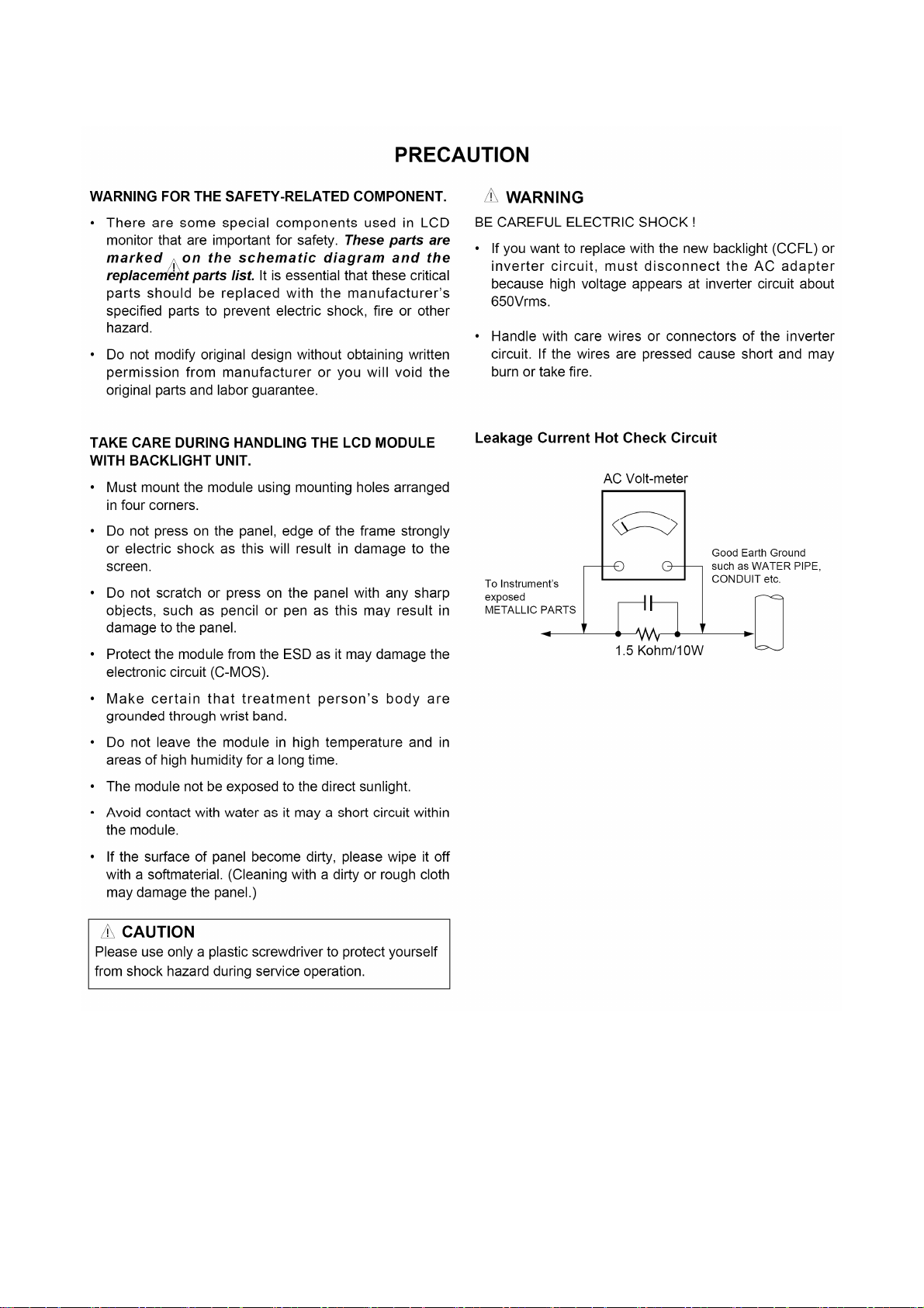
PRECAUTIONS .......................................................3
TIMING CHART .......................................................7
DISASSEMBLY ........................................................8
BLOCK DIAGRAM...................................................11
DISCRIPTION OF BLOCK DIAGRAM .................. 13
ADJUSTMENT ...................................................... 15
SERVICE MODE ......................................................... 17
TROUBLESHOOTING GUIDE .............................. 18
WIRING DIAGRAM ................................................... 24
EXPLODED VIEW...................................................... 25
REPLACEMENT PARTS LIST ................................. 27
SCHEMATIC DIAGRAM......................................... 35
SPECIFICATIONS
1. LCD CHARACTERISTICS
Type : TFT Color LCD Module
Active Display Area : 18.51 inch
Pixel Pitch : 0.3 (H) x 0.3 (V)mm
Color Depth : 16.7M colors
Size : 430.4(H) x 254.6(V) x 13.0(D) mm(Typ.)
Interface : LVDS 2Port
Surface Treatment : Hard-coating(3H), Anti-Glare
Operating Mode : Normally White, Transmissive mode
Backlight unit: 2 CCFL
2. OPTICAL CHARACTERISTICS
2-1. Viewing Angle by Contrast Ratio > 10
Left : 70°min, 85°(Typ) Right : 70°min, 85°(Typ)
Top :60° min, 75°(Typ) Bottom : 70°min,85°(Typ)
2-2.Luminance :250Cd / m
:170Cd / m
2-3. Contrast Ratio : 600(min), 1000(Typ)
3. SIGNAL (Refer to the Timing Chart)
3-1. Sync Signal
Type : Separate Sync, SOG (Sync On Green)
3-2. Video Input Signal
1) Type : R, G, B Analog
2) Voltage Level : 0~0.7 Vp-p
3) Input impedance: 75
3-3. Operating Frequency
Horizontal : 30 ~ 61kHz
Vertical : 56 ~ 75Hz
2
(min), 300Cd / m2 (Typ) -6500K
2
(min) -9300K
4. Max. Resolution
D-sub Analog : VESA 1360 x 768 @ 60 Hz
5. POWER SUPPLY
5-1. Power : AC 100-240V~ 50/60Hz 0.8A
5-2. Power Consumption
On Mode : 21 W(Typ.)
Sleep Mode: 1 W
Off Mode : 1 W
6. ENVIRONMENT
6-1. Operating
Temperature : 10°C~35°C
Humidity: 10 % to 80 % non-Condensing
6-2. Storage
Temperature: -20°C to 60 °C
Humidity: 5 % to 90 % non-Condensing
6-3. MTBF : 70000 Hours (Not include panel)
Lamp Life : Depend on Module spec
7. DIMENSIONS (with Stand)
Width : 44.84 cm (17.65 inches)
Depth : 35.79 cm (14.09 inches)
Height : 19.84 cm (7.81 inches)
8. WEIGHT (excl. packing)
Weight : 3.3 kg (7.28 lbs)
http://www.wjel.net
- 2 -
http://www.wjel.net
- 3 -
http://www.wjel.net
- 4 -
http://www.wjel.net
- 5 -
http://www.wjel.net
- 6 -
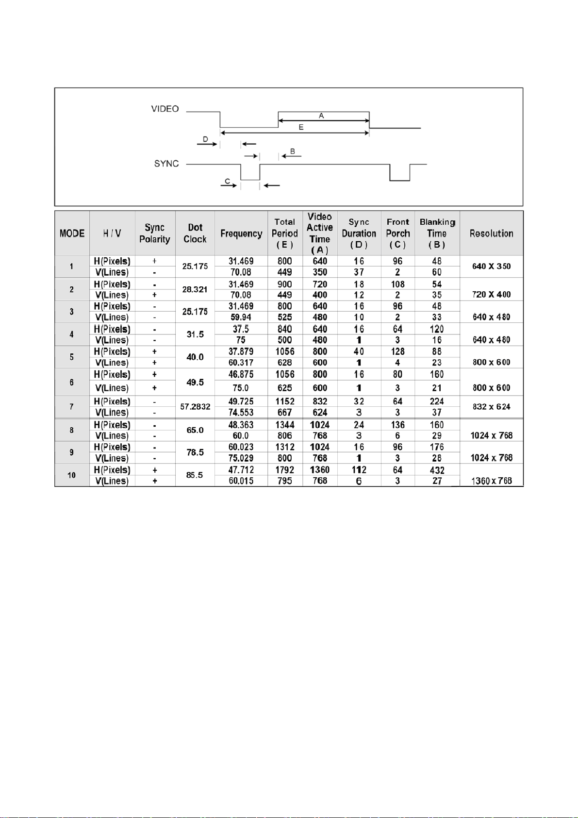
TIMING CHART
http://www.wjel.net
- 7 -
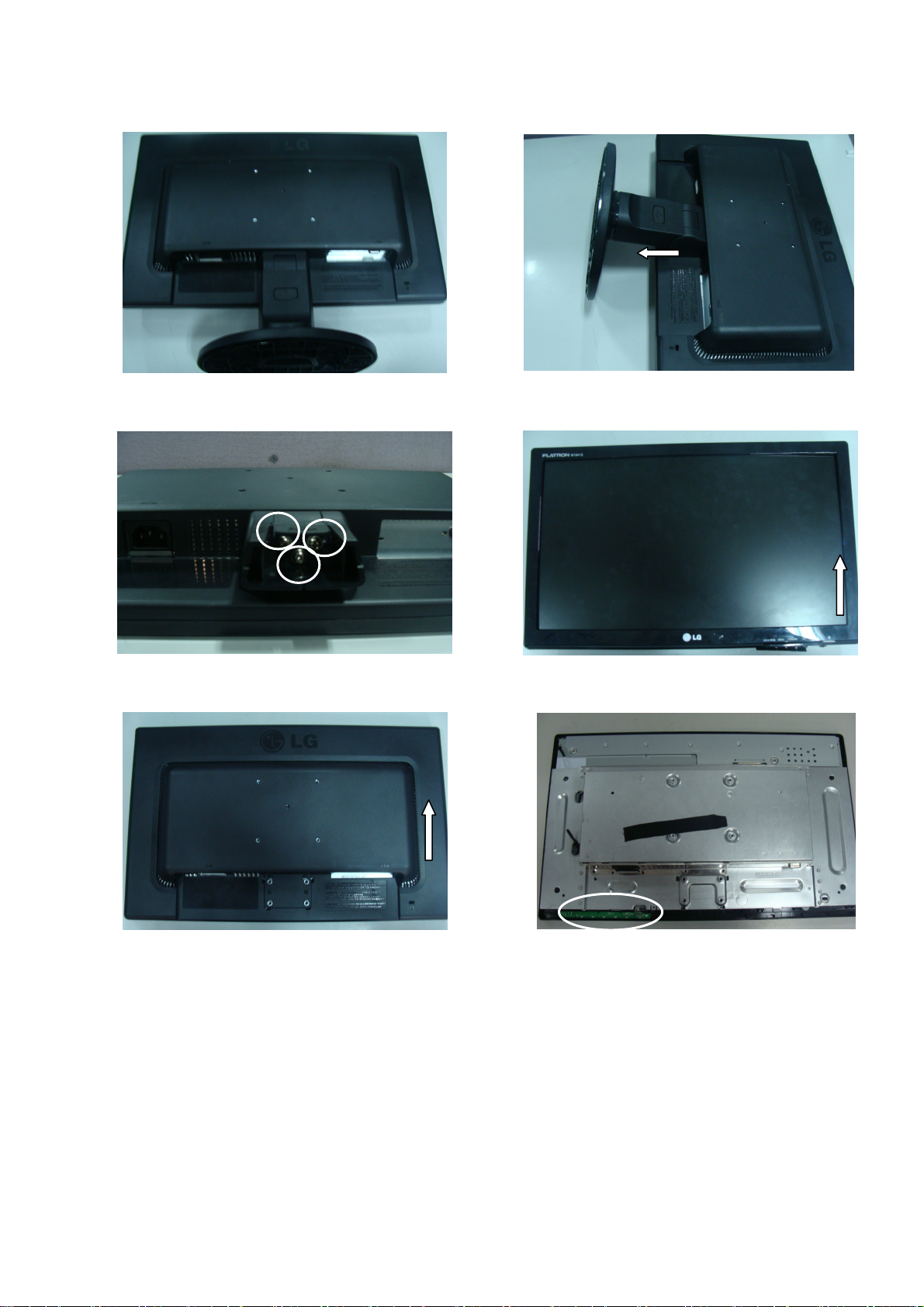
DISASSEMBLY-Set
#1
Put the monitor on a soft flat.
#3
#2
Pull out the stand and the hinge cover.
#4
Remove the three screws.
#5
Put the front face down, disassembly back
cover.
http://www.wjel.net
Put the front cover upward. Then let the all
latches are separated.
#6
Pull the key board out of bezel.
- 8 -
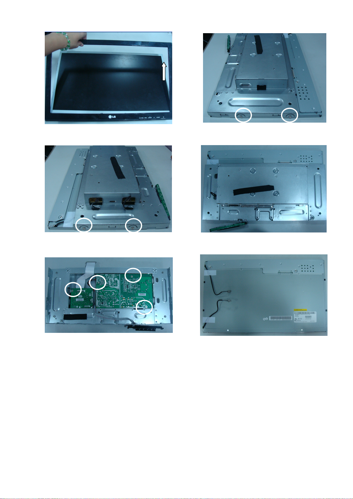
#7
Disassembly the bezel.
#9
#8
#10
Disassembly the connector and screw.
#11
Remove the screw.
Main board and power board.
http://www.wjel.net
#12
Disassemble the FFC cable.
The panel.
- 9 -
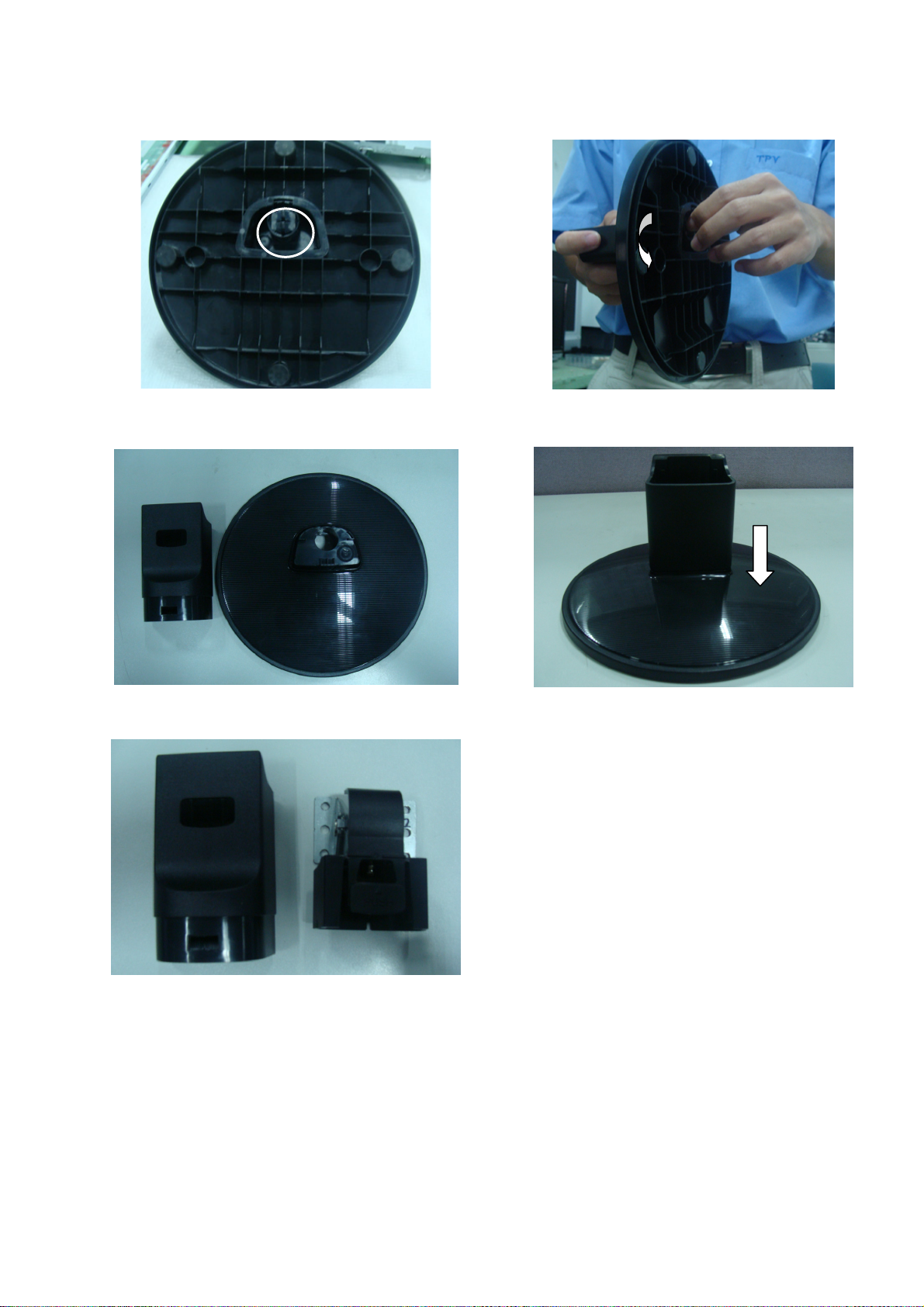
DISASSEMBLY-Stand
#1
Pull the Base Latches to inside until losing
elasticity.
#3
#2
Consequently, pull the stand body directly.
#4
Separate Stand Body & Stand Base.
#5
http://www.wjel.net
Separate the hinge and stand.
Fix Stand Base & Stand Body.
- 10 -
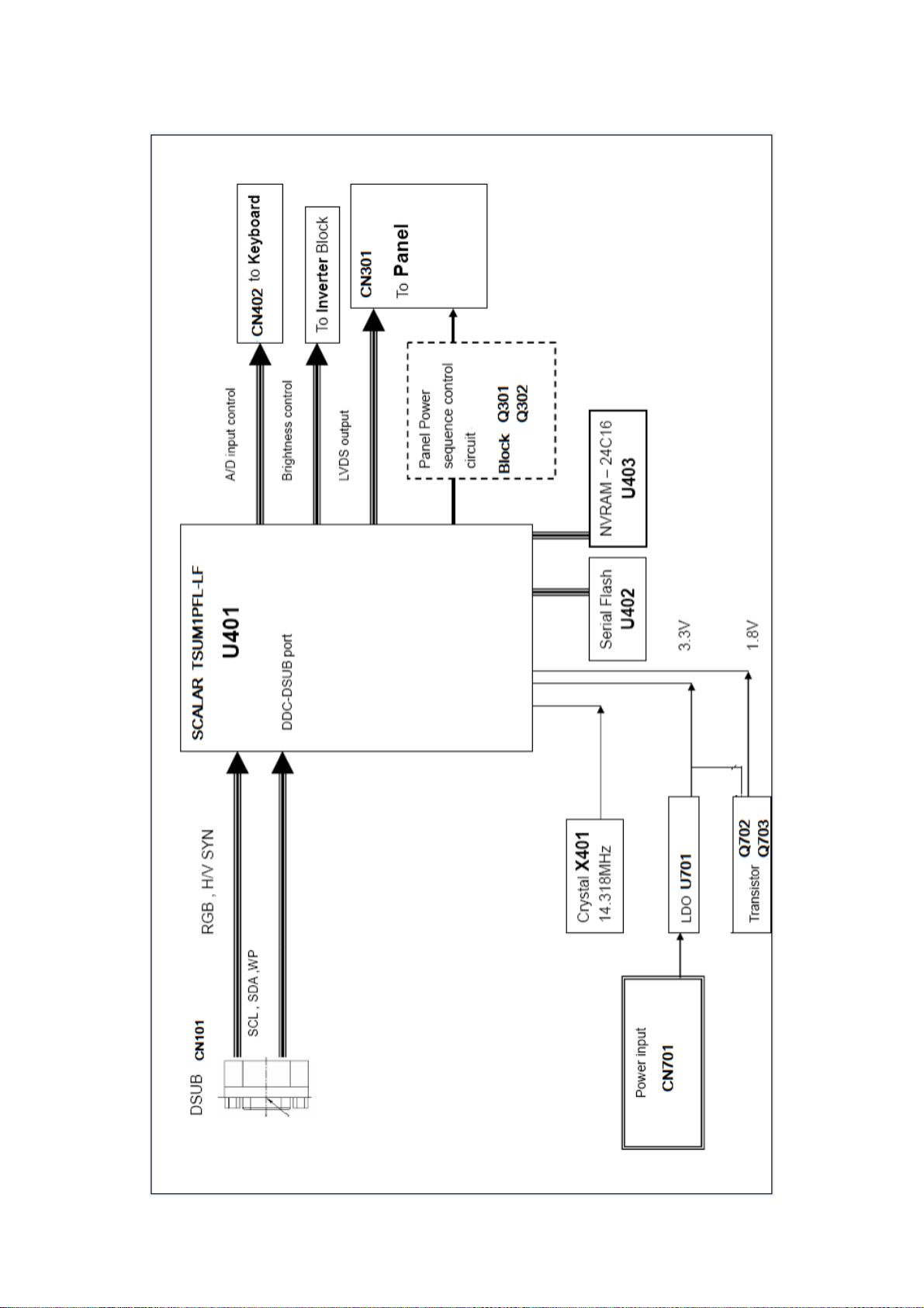
BLOCK DIAGRAM
http://www.wjel.net
- 11 -
Power
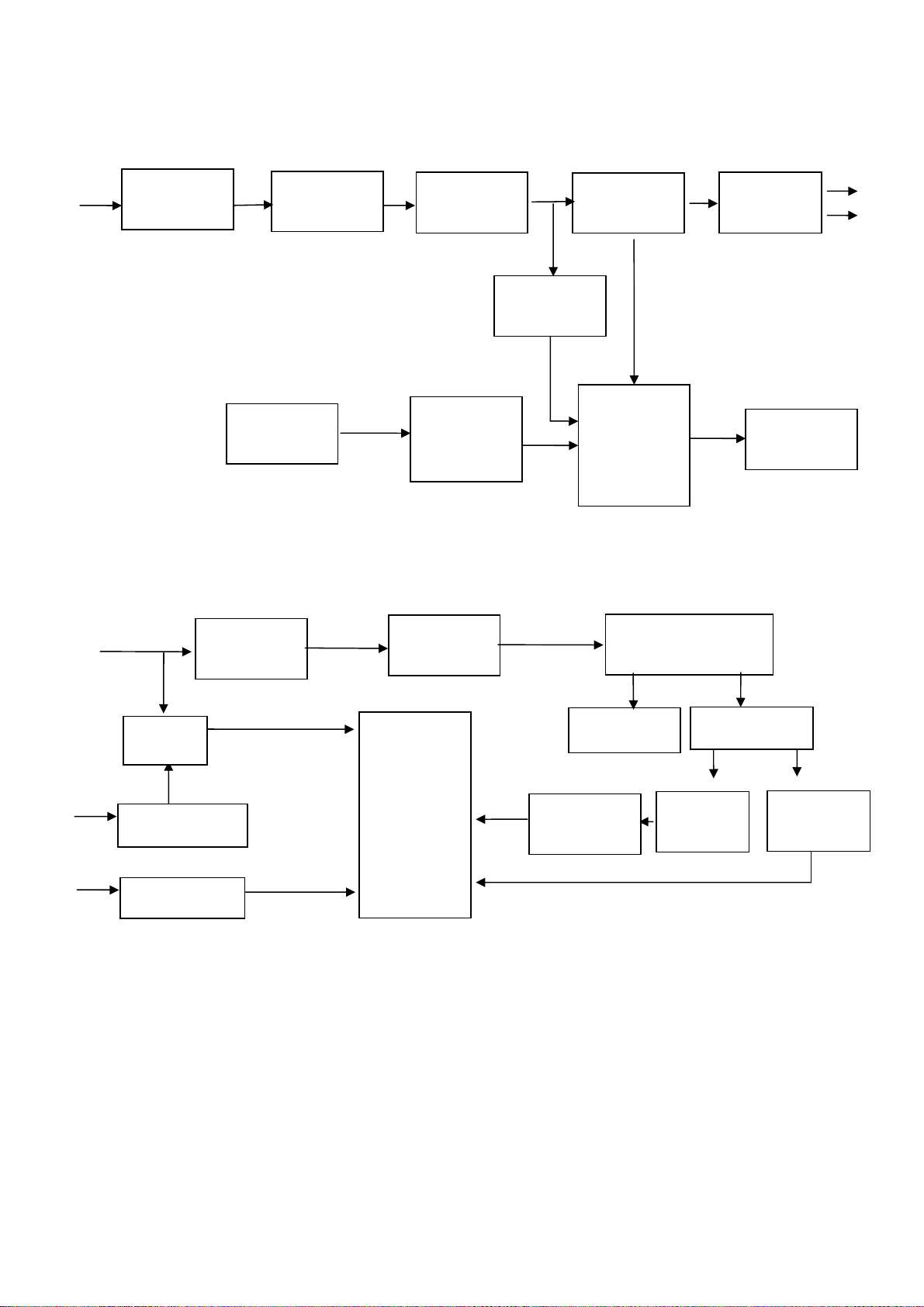
BLOCK DIAGRAM-POWER
100~240V
Inverter
EMI filter
12V
5V/12V
output OVP
Push-pull
circuit
Rush
prevention
Rectification
Feedback
control
circuit
Transformer
conversion
Starting
resistor
Transformer
Switching
circuit (PWM
control IC &
MOSFER)
LC resonance
Diode
rectifier
OVP protect
circuit
5V
12V
ON/OFF
ON/OFF circuit
DIM
DIM circuit
VDDA
PWM IC
OZ9938GN
OVP circuit
Feedback
circuit
2 CCFL lamps
Sampling
Lamp open
protection
http://www.wjel.net
- 12 -

DESCRIPTION OF BLOCK DIAGRAM
1. Video Controller Part.
This part amplifies the level of video signal for the digital conversion and converts from the analog video signal to
the digital video signal using a pixel clock.
The pixel clock for each mode is generated by the PLL.
The range of the pixel clock is from 79.5MHz to 90MHz.
This part consists of the Scaler, ADC converter, TMDS receiver and LVDS transmitter.
The Scaler gets the video signal converted analog to digital, interpolates input to 1360 X 768 resolution signal and
outputs 8-bit R, G, B signal to transmitter.
2. Power Part.
This part consists of the one 3.3V, and one 1.8V regulators to convert power which is provided 5V in Power board.
12V is provided for inverter, 5V is provided for LCD panel.
Also, 5V is converted 3.3V and 1.8V by regulator. Converted power is provided for IC in the main board.
The inverter converts from DC 12V to AC 700Vrms and operates back-light lamps of module.
3. MICOM Part.
This part is including video controller part. And this part consists of NVRAM which stores control data, Reset IC and
the Micom.
The Micom distinguishes polarity and frequencies of the H/V sync are supplied from signal cable.
The controlled data of each mode is stored in NVRAM.
http://www.wjel.net
- 13 -
 Loading...