

Page 1
ROBOTIC CLEANER
SERVICE MANUAL
MODEL : VR657* LVMP
VR657** LVMP
VR95** Ser
VR86** Ser
Caution
Please read the safety cautions of this booklet
before the maintenance of the product.
P/NO : MFL67646518
July, 2015
Printed in Korea
Page 2

Table of Contents
1. Product SPEC
2. Structure and Name of Each Part
3. Cautions and Methods during the Usage
4. How to Use Main Body Operation Buttons and Remote Controller
5. Technical Descriptions of the Parts
6. Safety Cautions and Verifications During the Repair
7. How to Disassemble/Assemble and Repair Major Parts
8. Cabling Diagram
9. Types of Defects and the Countermeasures
10. How to Use R-Manager RK diagnosis program
11. How to Use Black Box Viewer
12. Deal Drawing of the Structure and List of the Parts
-2-
Page 3
Product Specifications
■ Main Unit
ITEM LG Robot Cleaner
MODEL
Battery (Fully Charging)
Power Consumption
Charging Time
Use Time
Traveling Velocity
Cleaning Mode
Weight
External Dimensions
Accessary
Scheduled Cleaning / Error Displaying / Navigation / Auto/Manual Recharging /
Main Function
Spot Cleaning / Repeat Cleaning / My Space Cleaning / Cell by Cell cleaning /
VR657*LVMP / VR657**LVMP / VR95** Ser / VR86** Ser
Li ion, DC 16.8V
58W
3 hours
Approx. 100 minutes
(based on general wooden oor )
0.35 m/s
zigzag cleaning / Cell by Cell Cleaning / My Space Cleaning / Spot Cleaning
3kg
340mm x 340mm x 89mm
Home station / remote controller / Filter / Cleaning Brush / Brush
Turbo Mode / Learning Mode / Obstacle Sensing / Anti-Plunge function /
Corner Clean / Voice Messaging / Map Drawing /
Zigzag Cleaning /
■ Home Station
ITEM Home Station
Model
Rating
Power Consumption
Output Voltage/Current
■ Remote Controller
ITEM AKB73296002
Battery
Type
Operating Range
Size(WxLxH)
VR621
AC 220V, 60Hz
23W
DC 17.1V / 1.1A
DC 3V(AAA, 2ea)
Infra Red(38kHz)
5m
45 X 22 X 115 mm
-3-
Page 4
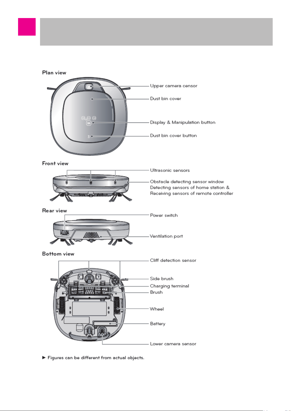
Structure and Name of Each Part
– Robot Cleaner
-4-
Page 5

Structure and Name of Each Part
– Robot Cleaner
-5-
Page 6
Cautions and Methods during the Usage
-6-
Page 7
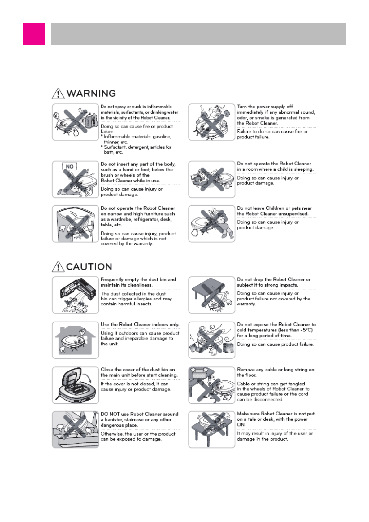
Cautions and Methods during the Usage
-7-
Page 8
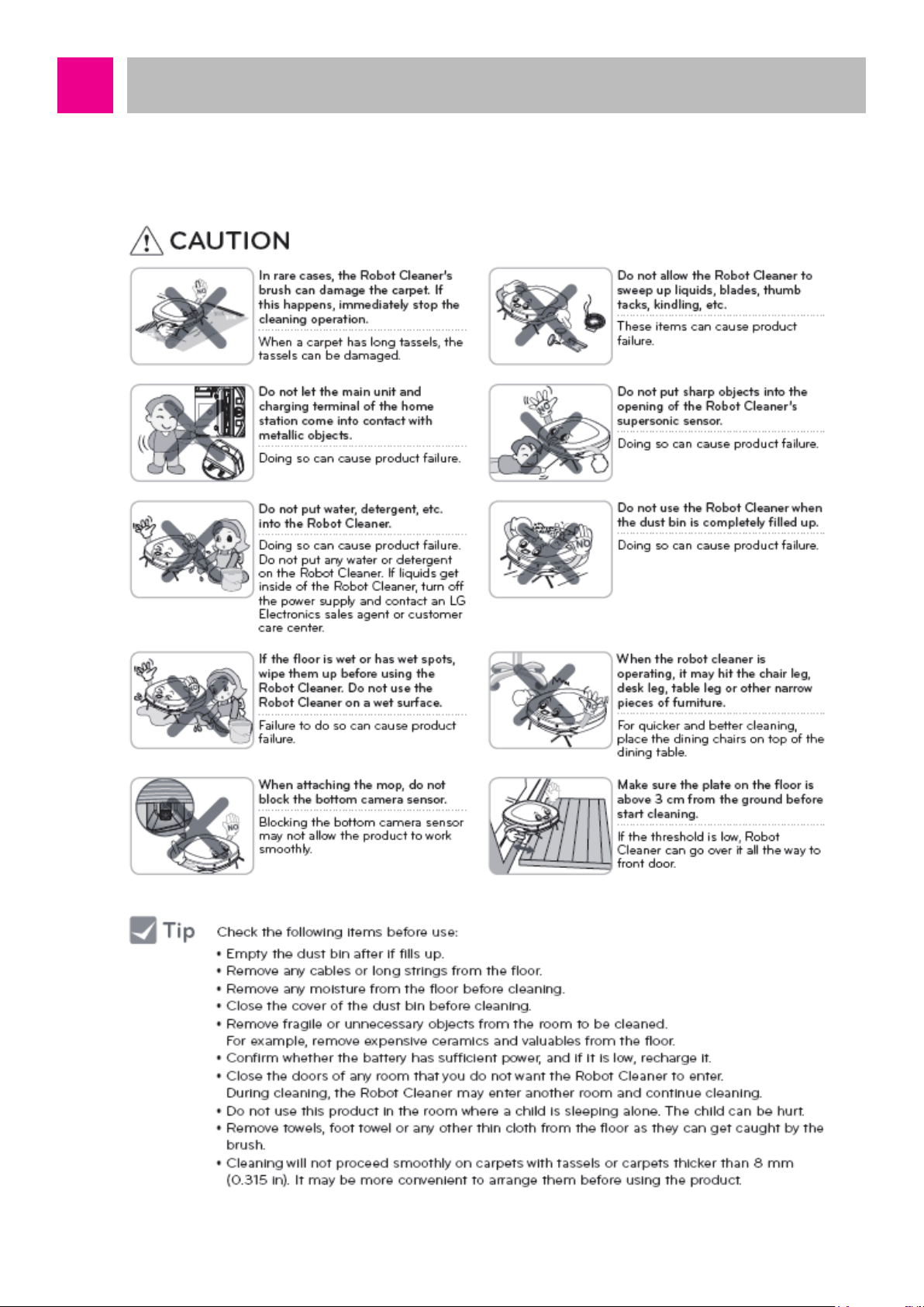
Cautions and Methods during the Usage
-8-
Page 9
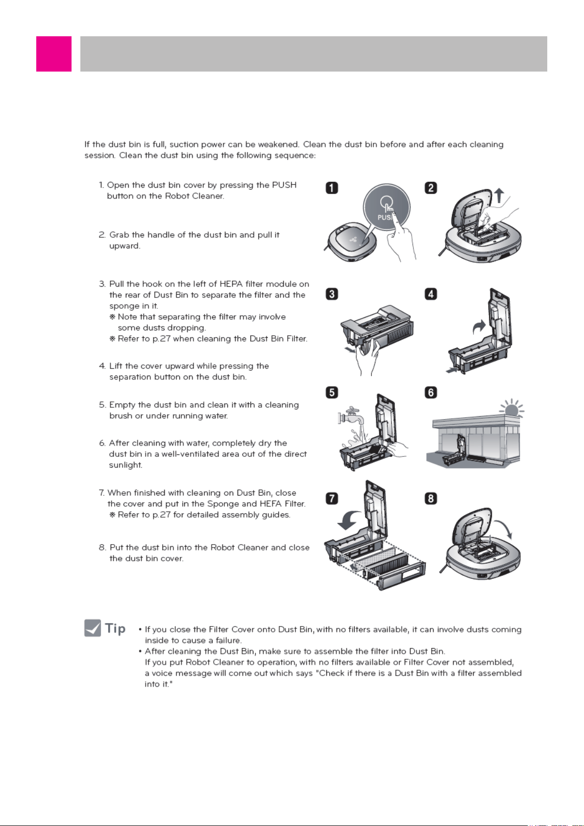
Cautions and Methods during the Usage
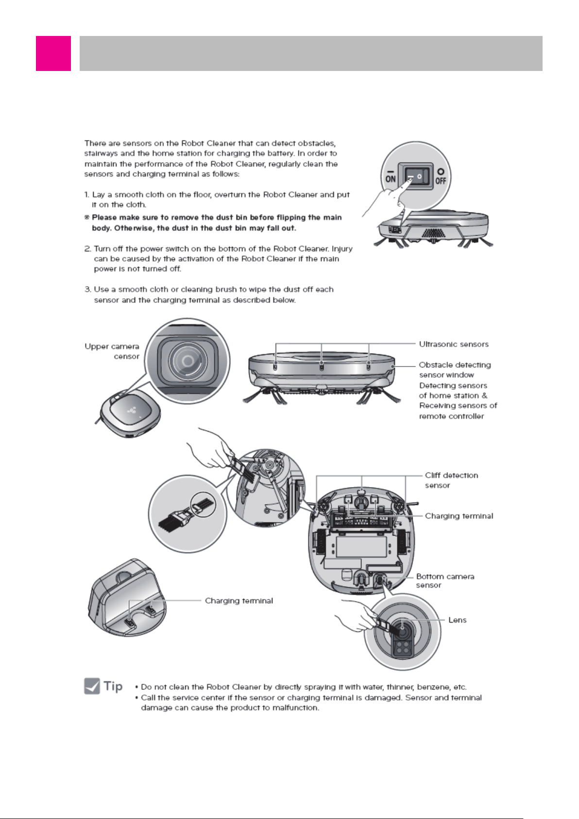
1. About Dust Bin
-9-
Page 10
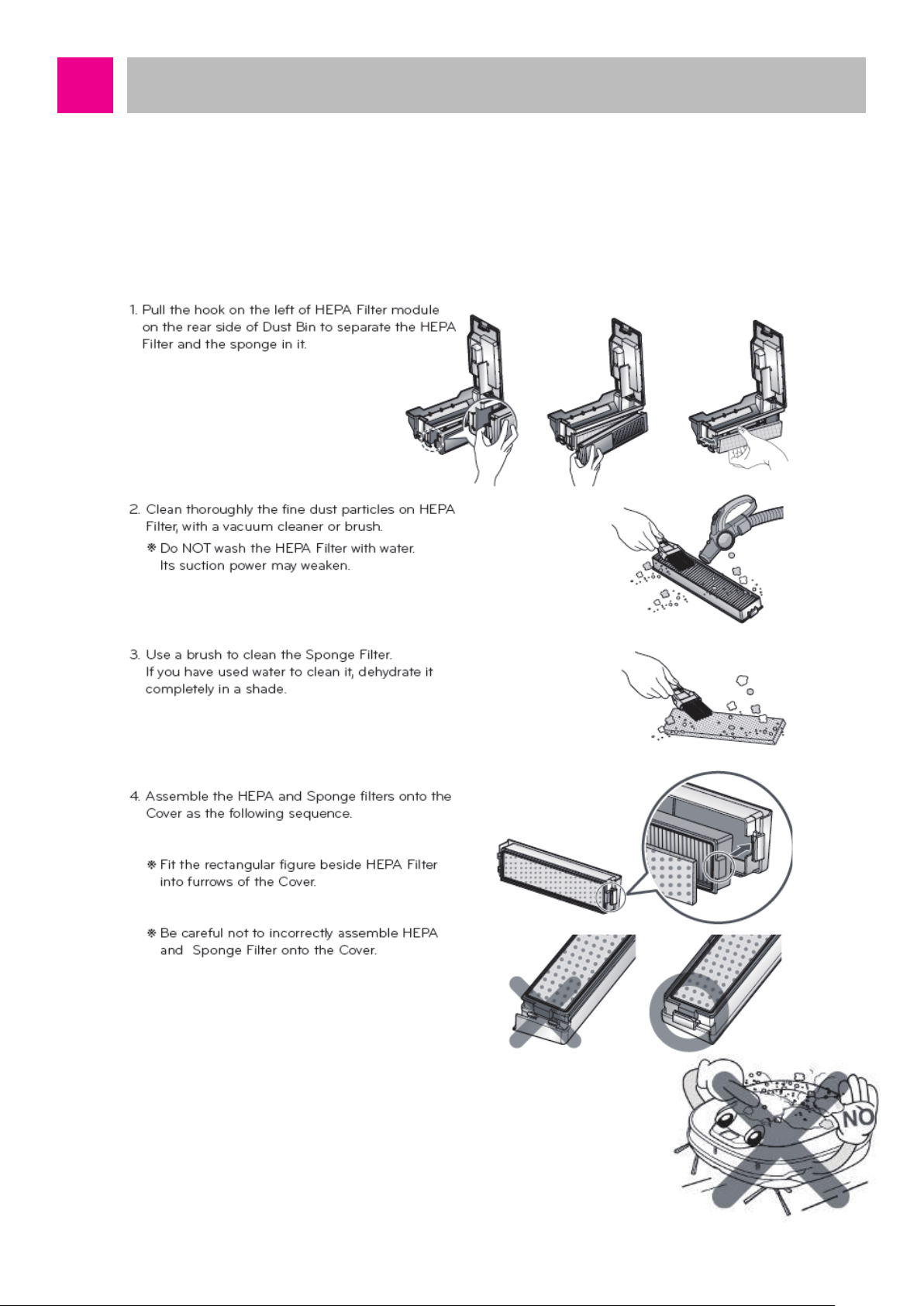
Cautions and Methods during the Usage
2. About Filter
■
Dust Bin Filter
It is recommended to clean the dust bin filter with HEPA 11 once a week. During the cleaning,
clean thoroughly with cleaning brush and the cleaner. Never clean the filter with water. When it
is washed with water, the cleaning performance will be degraded.
Make sure to install the dust bin filter (HEPA filter, sponge
filter) to the dust bin after the cleaning.
If the dust bin or dust bin filter is not installed, dust may enter
inside Roboking and cause disorder.
-10-
Page 11

Cautions and Methods during the Usage
3. About Agitator
If foreign object is stuck in the agitator, it decreases the rotation speed and degrades the
cleaning performance to cause disorder. Especially, after cleaning hair or hair of pets, make
sure to clean the agitator. Clean periodically after 10 usages in ordinary homes.
If the agitator stops by foreign object during the cleaning, a voice alarm of “check foreign object
in the agitator at the bottom” will sound. At this time, remove the foreign object stuck in the
agitator before the usage.
Side agitator rotates synchronized with the bottom agitator. If the bottom agitator does not
rotate, the side agitator will not rotate either.
-11-
Page 12

Cautions and Methods during the Usage
4. Cleaning the Side Brush
-12-
Page 13
Cautions and Methods during the Usage
5. Cleaning the Sensor / Charging Terminal
-13-
Page 14
Cautions and Methods during the Usage
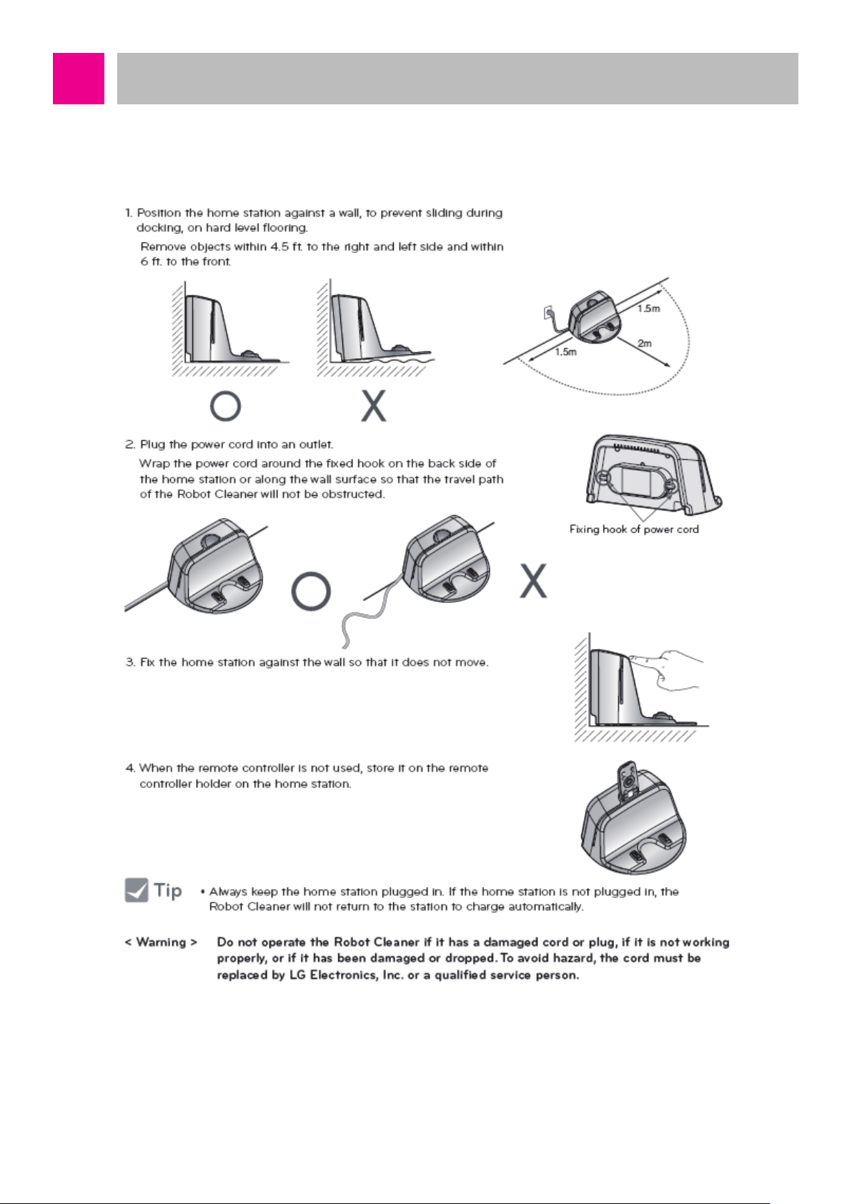
6. How to Install the Home Station
-14-
Page 15
Cautions and Methods during the Usage
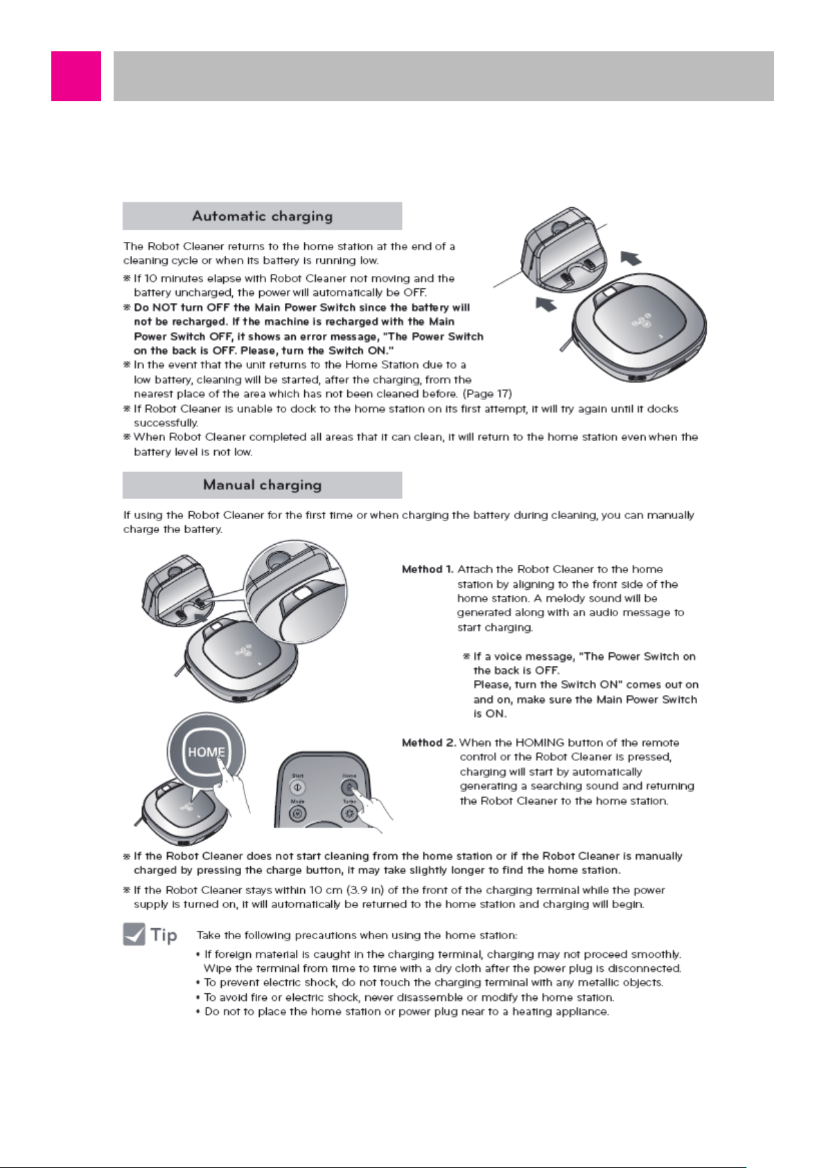
7. How to Charge the Battery
-15-
Page 16
Cautions and Methods during the Usage
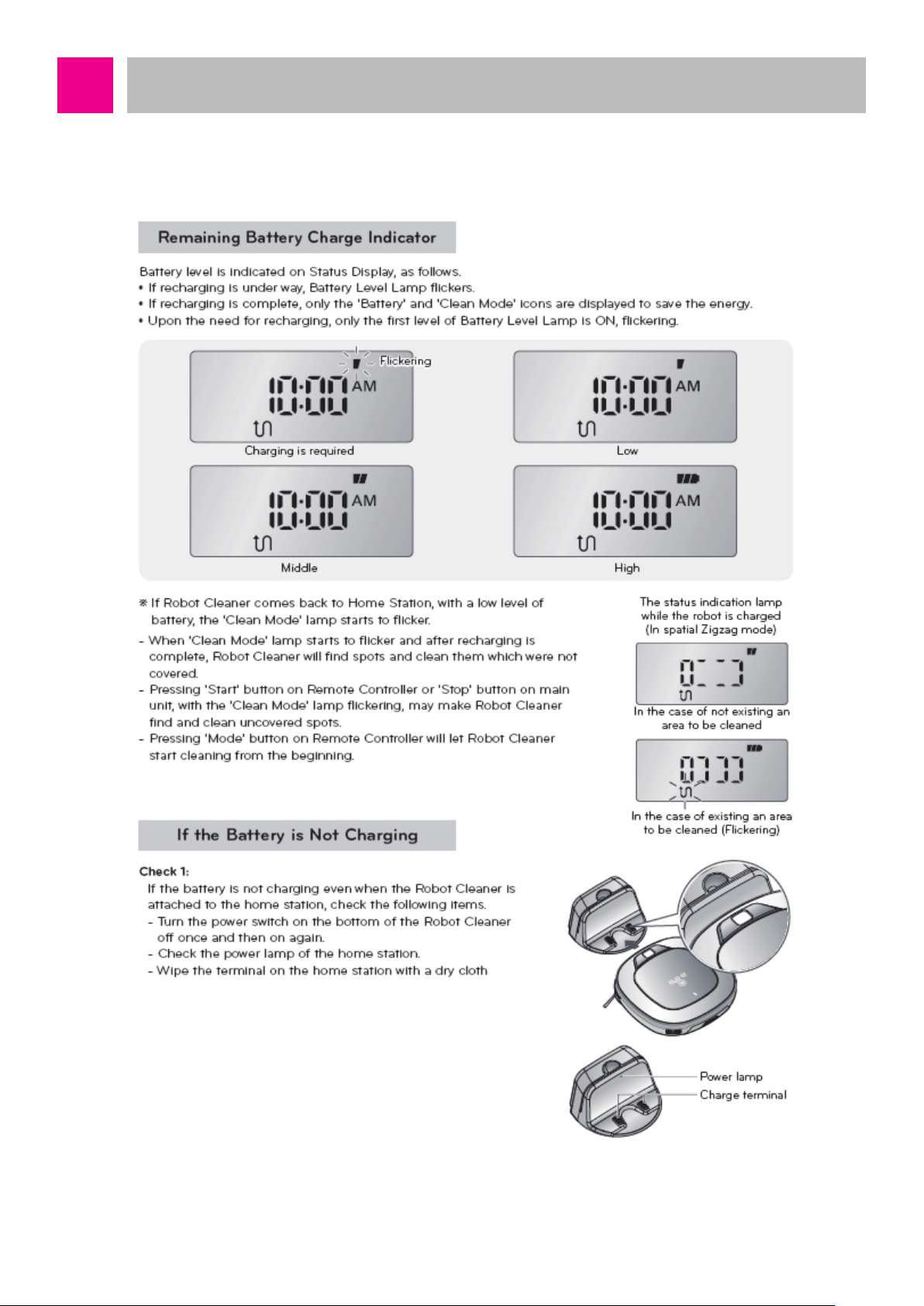
8. Remaining Battery Charge Indicator
-16-
Page 17
How to Use Main Body Operation Buttons
and Remote Controller
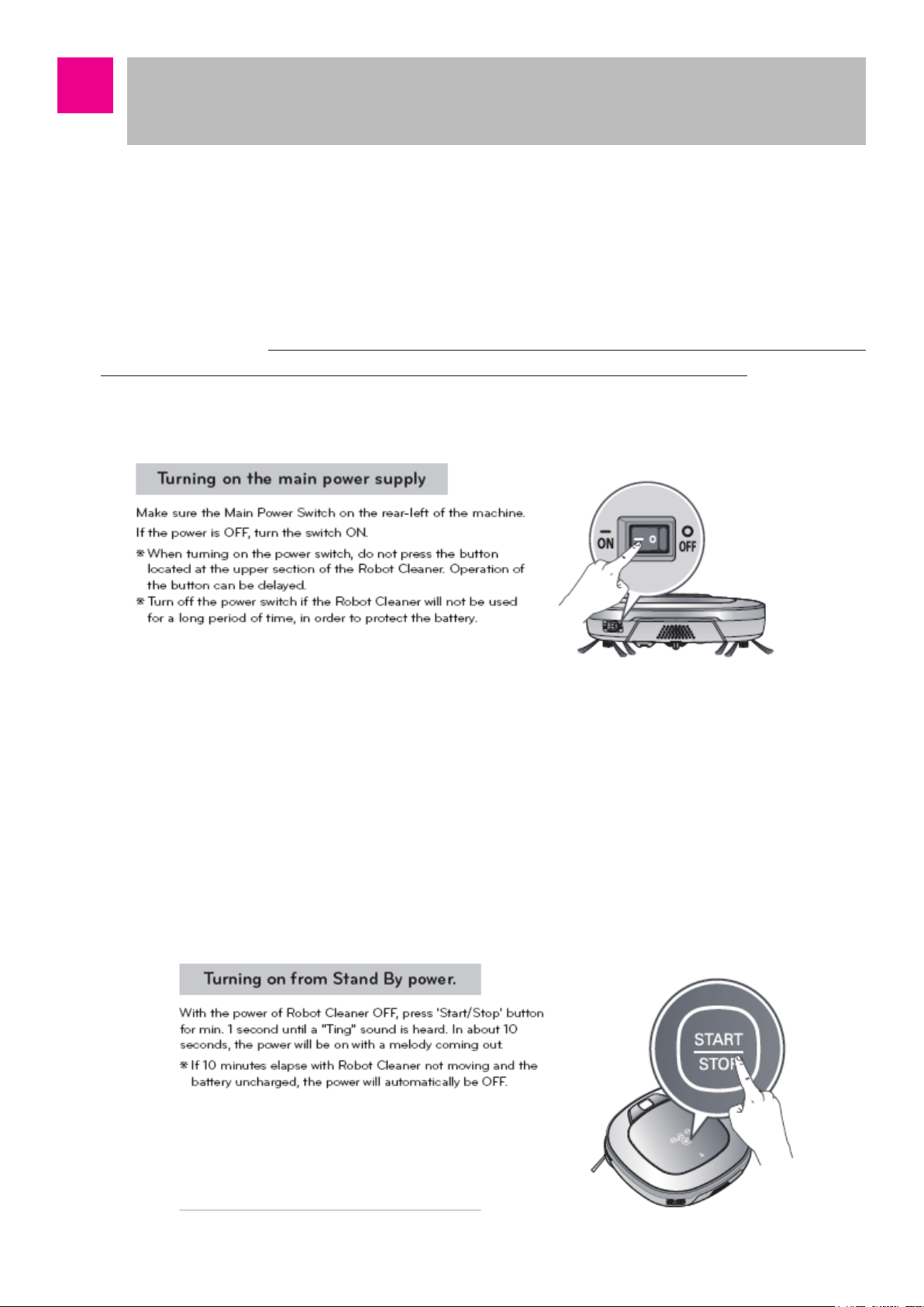
■ Turning ON/OFF the Power Button
The power switch at the left backside of the main body is connected between the battery and the Main circuit to
function to supply or block the power. Also, it is connected between the recharging connector of the main body
and the Main circuit to functions to supply or block the power of the recharging station.
When the main body power switch remains in ON state, the product can be turned on by pressing the button
on the main body, and recharge is possible. If the power is not turned ON even if the power button on the
main body is pressed, or if power is not turned on even if the main body is connected to the recharging
station, check the status of the main power switch at the left backside of the main body.
※ When you turn on the main power button, do not turn it on while pressing the button at the top of the cleaning
robot. Button operation may be delayed.
Even if the main body power switch is turned on, Micom does not operate, so there is no change is the status
indication window. To start Micom, press the start/stop button of the main body for 1 second after turning on
the main body power switch. Then, Micom will start, LED of the screen display window will be turned on, and
Booting will start. Booting time may be different for each model, and when the Booting is over, it converts to
standby state with a melody.
In the standby state, if the start/stop button of the main body is pressed for 2 seconds or longer, the power will
be turned off with the ending melody.
It is the state with the power off, but a small amount of electricity is used for button operation, so when it is left
alone for long period of time, the battery may be consumed and power may not be turned on. When it is not
used for long period of time, please store it with the power switch turned off.
-17-
Page 18
How to Use Main Body Operation Buttons
and Remote Controller
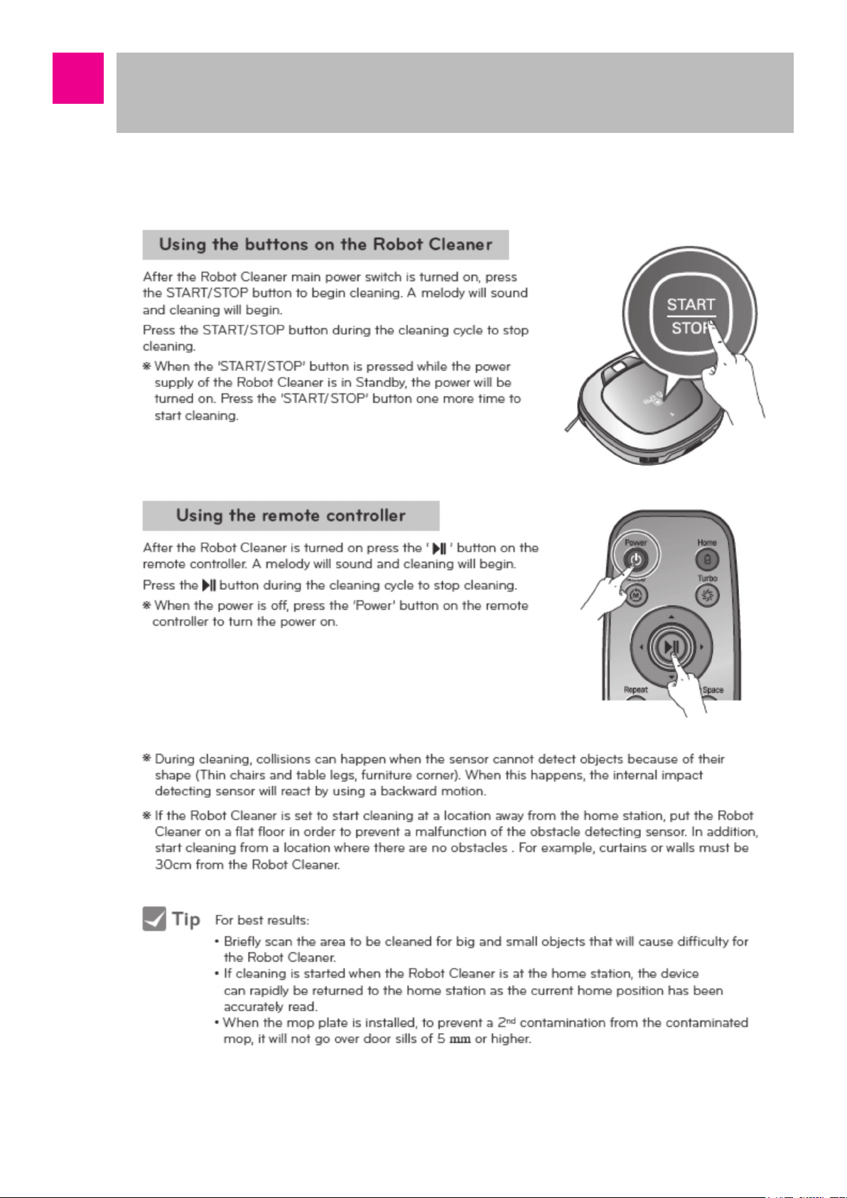
■ How to Start and Stop Cleaning
-18-
Page 19
How to Use Main Body Operation Buttons
and Remote Controller
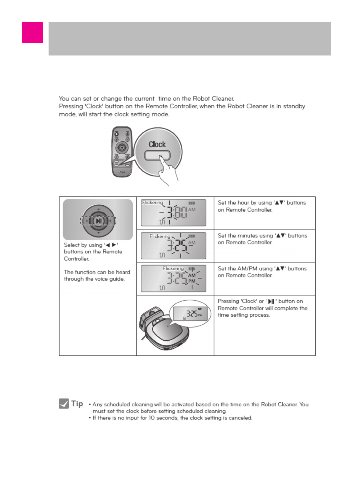
■ Time Setting
-19-
Page 20
How to Use Main Body Operation Buttons
and Remote Controller
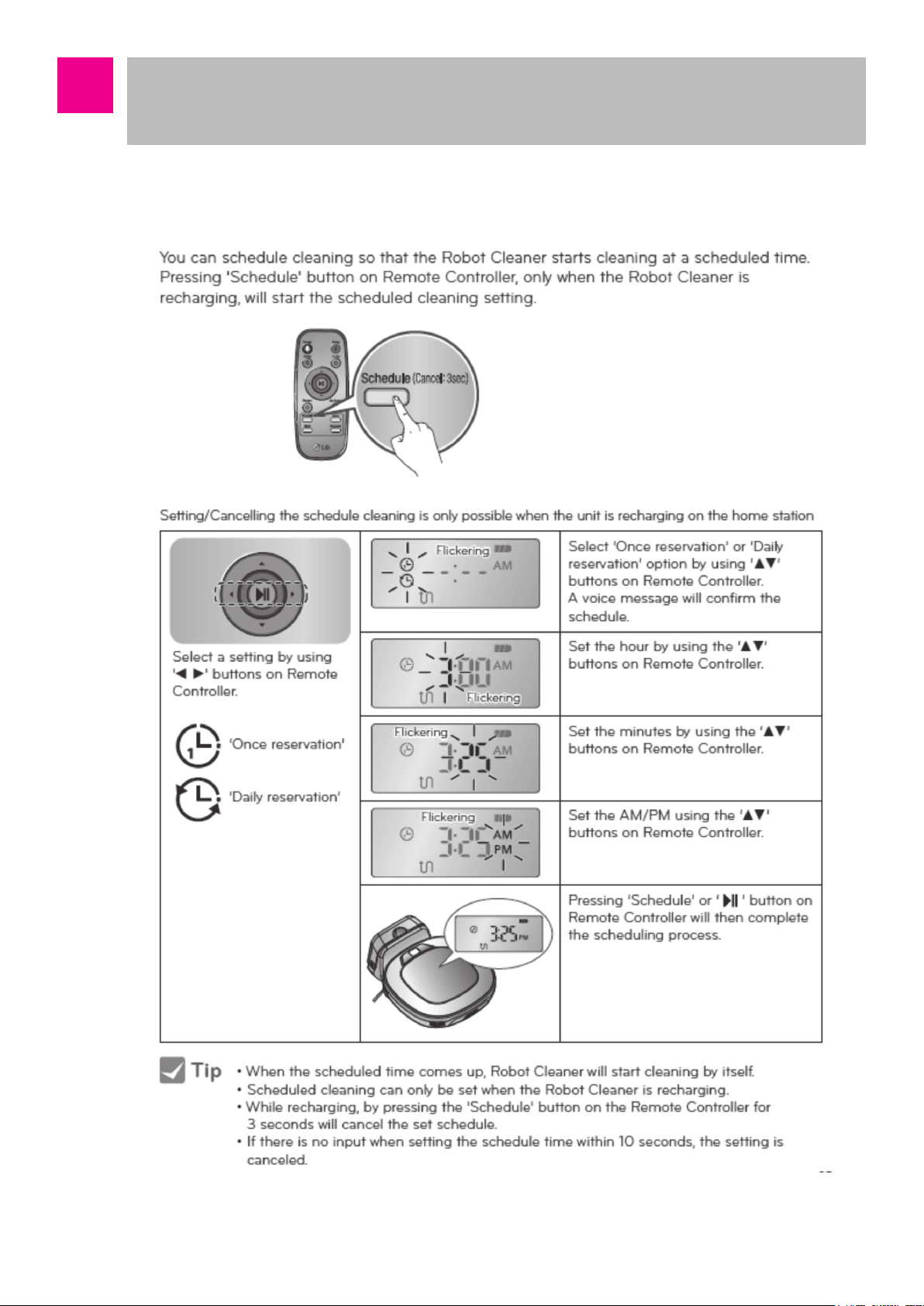
■ Schedule Cleaning
-20-
Page 21
How to Use Main Body Operation Buttons
and Remote Controller
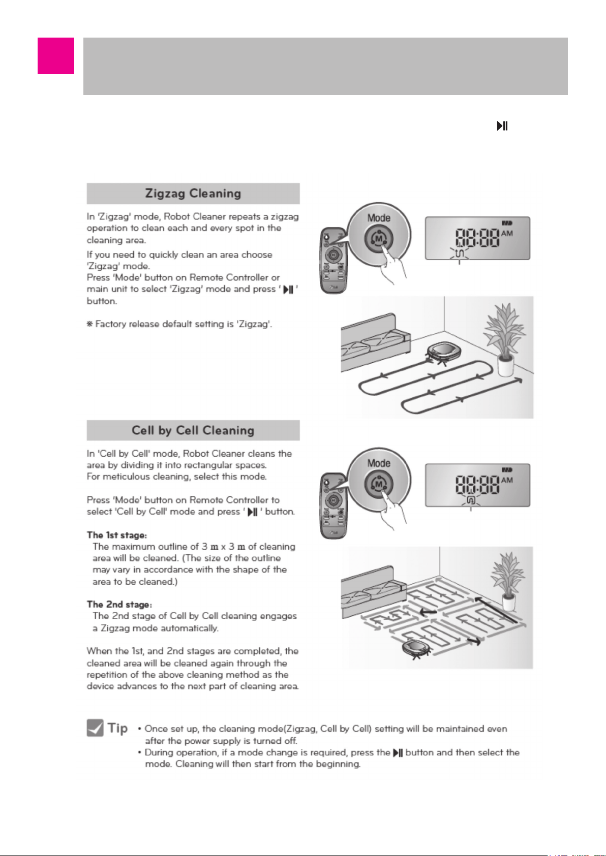
■ Cleaning Modes ※ If you want to change the mode during the operation, press and select
the mode.
-21-
Page 22
How to Use Main Body Operation Buttons
and Remote Controller
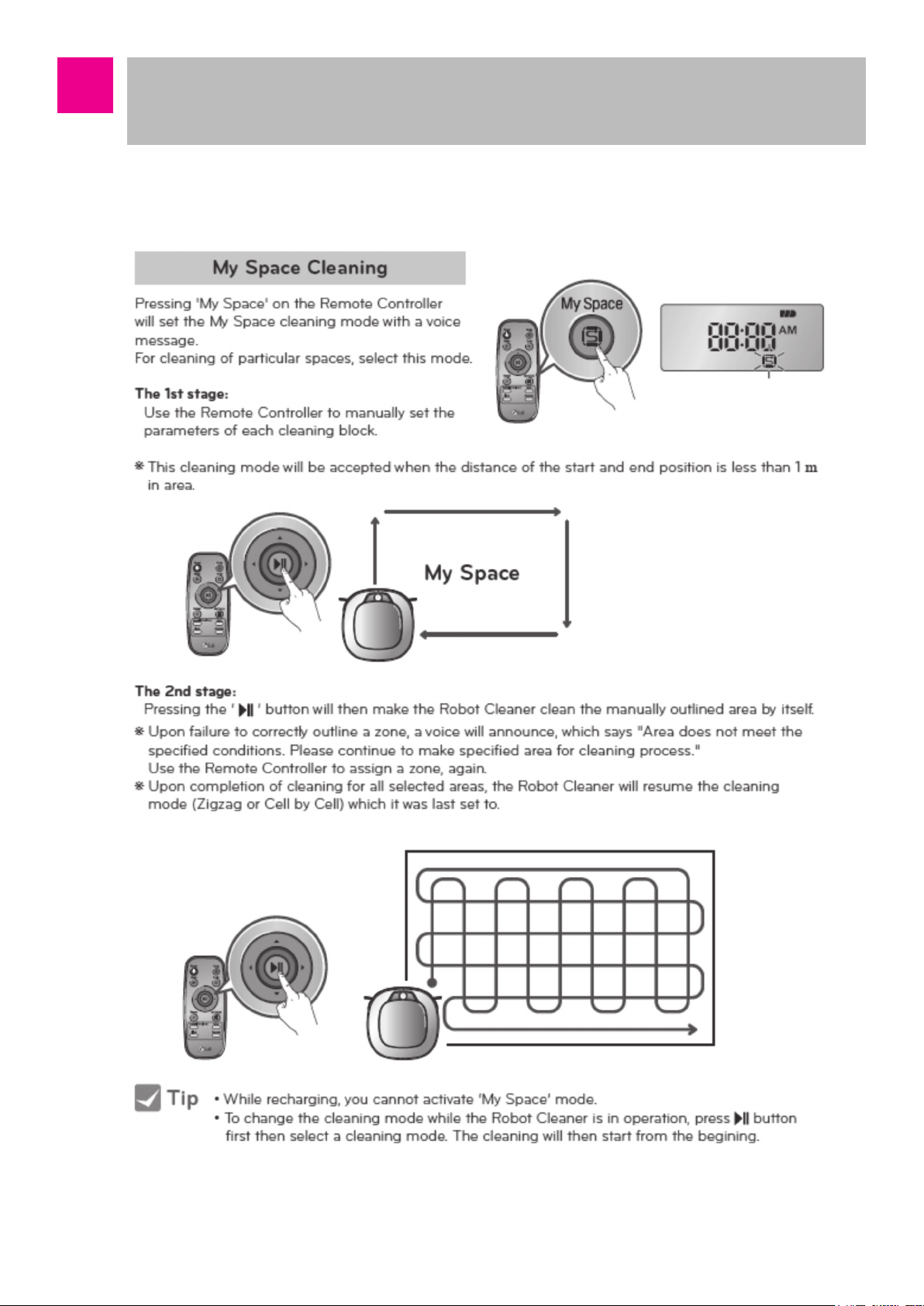
■ My space clean
-22-
Page 23
How to Use Main Body Operation Buttons
and Remote Controller
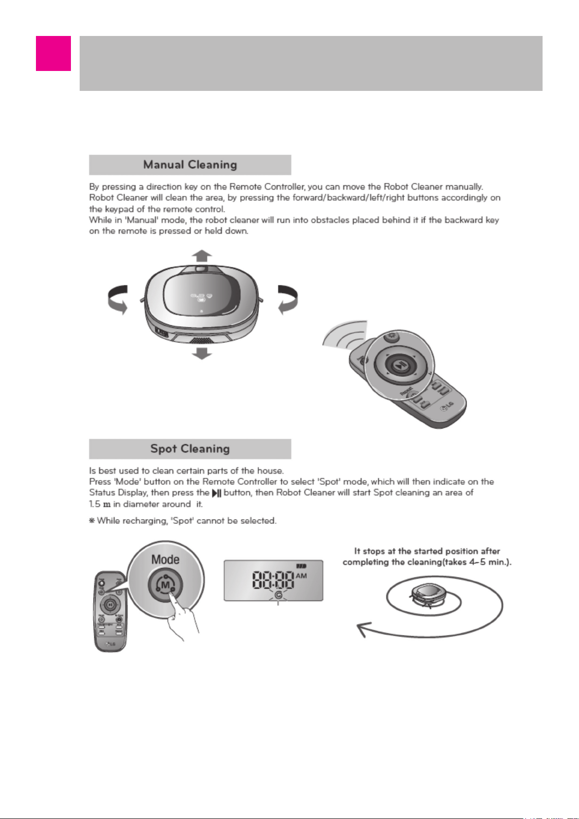
■ Manual Cleaning and Spot Cleaning
-23-
Page 24
How to Use Main Body Operation Buttons
and Remote Controller
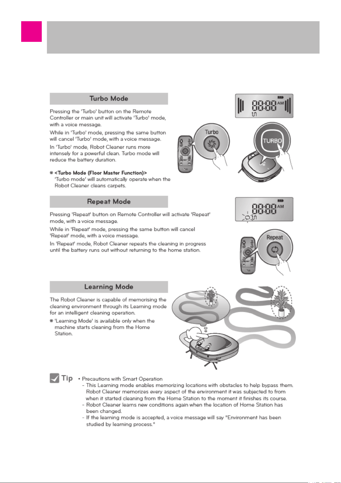
■ Turbo Mode, Repeat Mode and Learning Mode
-24-
Page 25
How to Use Main Body Operation Buttons
and Remote Controller
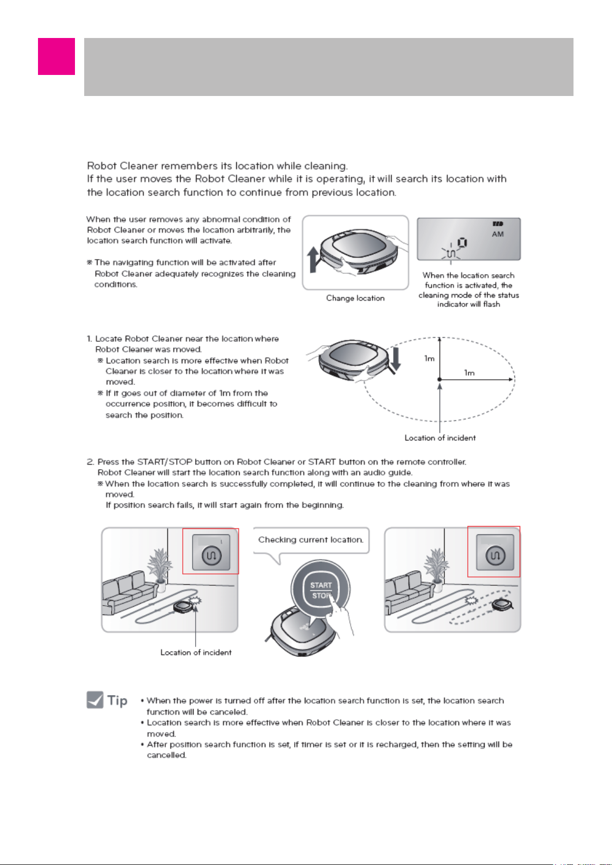
■ Location Search Function
-25-
Page 26
How to Use Main Body Operation Buttons
and Remote Controller
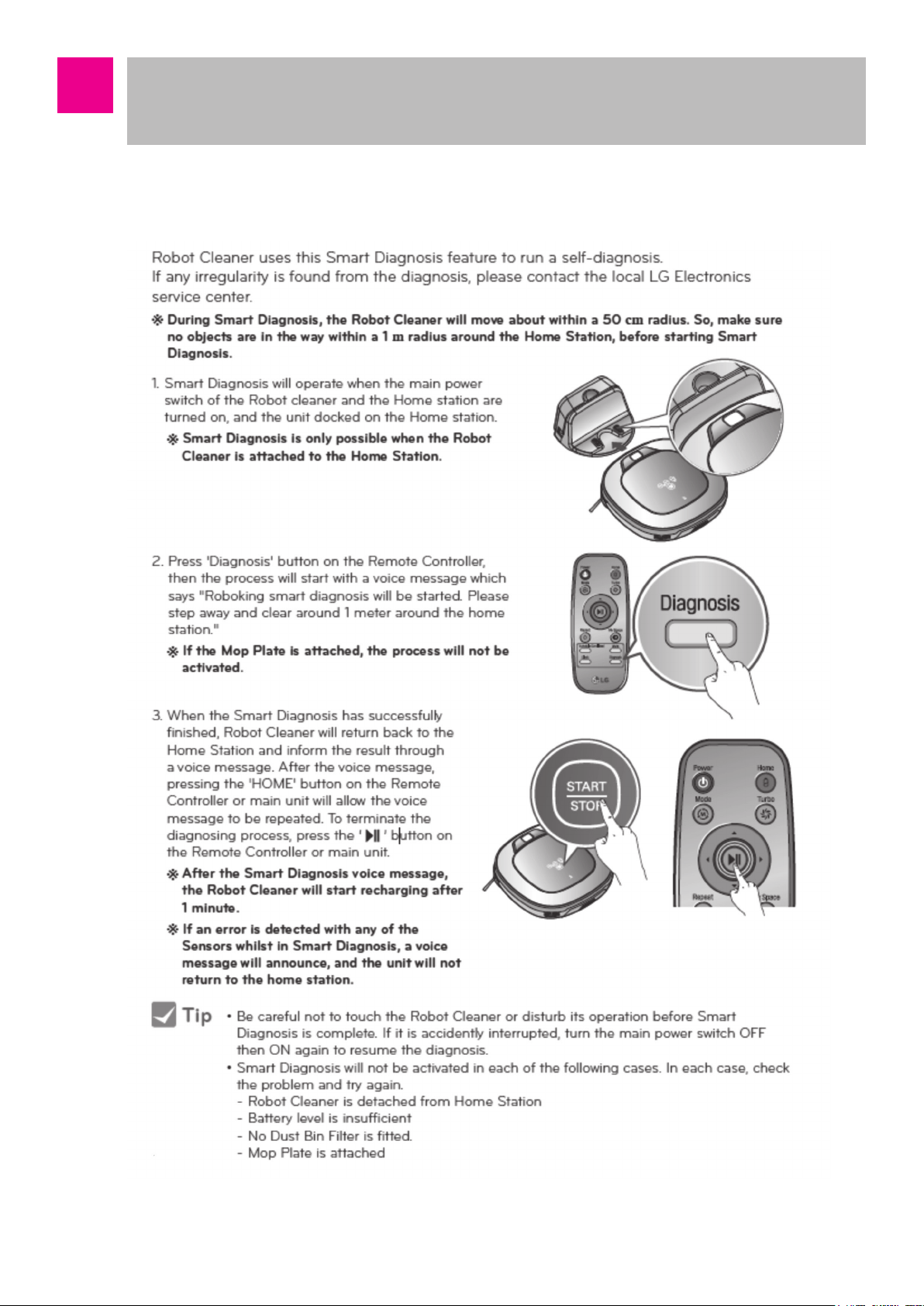
■ Smart Diagnosis
-26-
Page 27
How to Use Main Body Operation Buttons
and Remote Controller
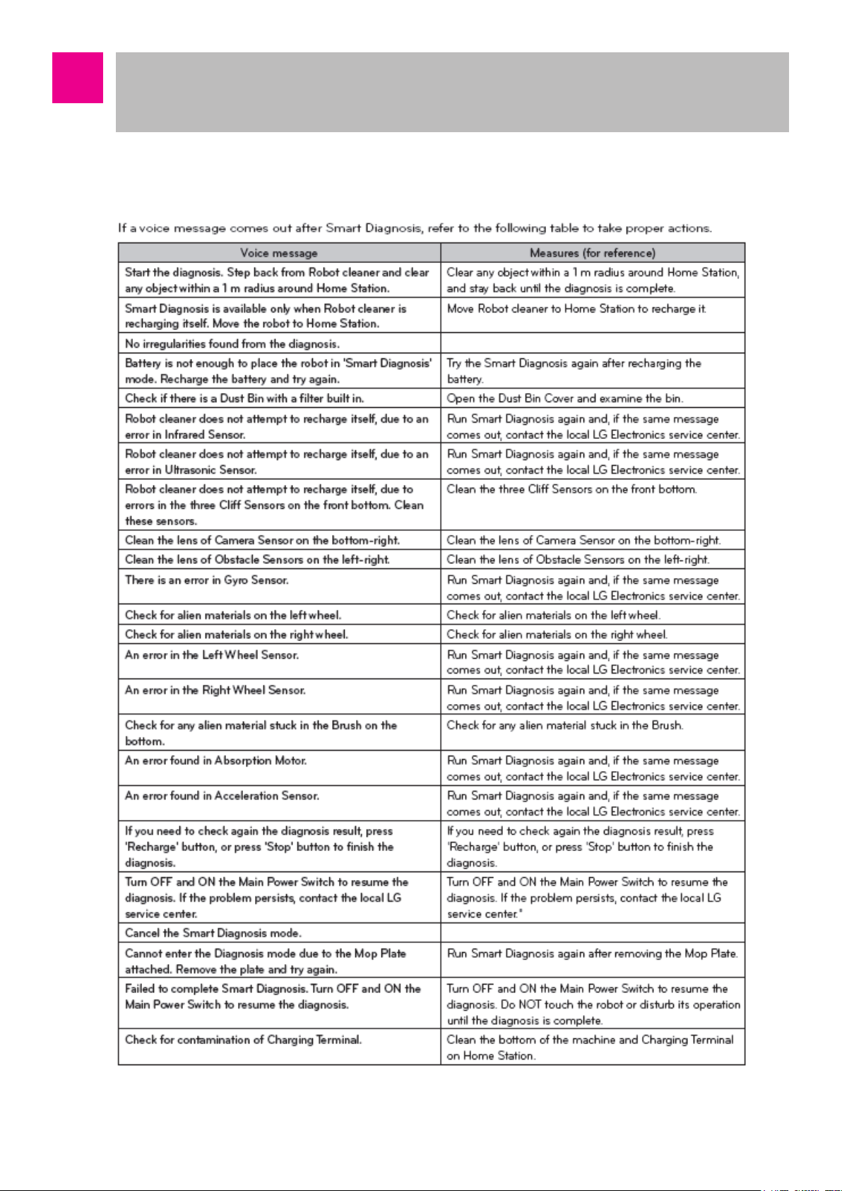
■ Smart Diagnosis
-27-
Page 28
Technical Descriptions of the Parts
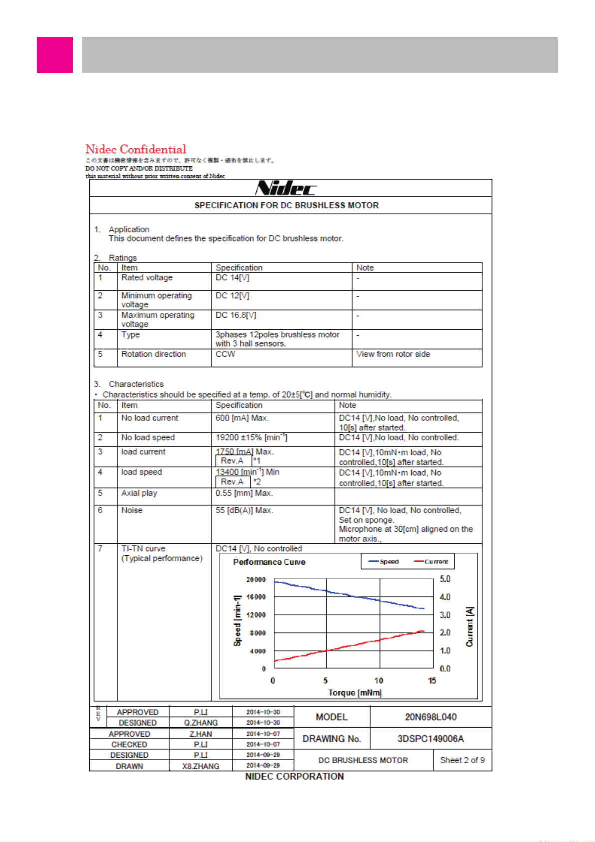
■ Suction Motor
Manufacturer: Nidec
-28-
Page 29
Technical Descriptions of the Parts
■ Agitator Motor
Manufacturer: STANDARD
-29-
Page 30
Technical Descriptions of the Parts
■ Wheel Motor
Manufacturer: SHARP
-30-
Page 31

Technical Descriptions of the Parts
■ Wheel Motor
Manufacturer: SHARP
Model Name
Operation Voltage
Measurable Distance
Connector Voltage Output (L=30)
Minimum/Maximum Distance
Voltage Difference
Average Current Supply
GP2Y051SK0F
DC 4.5V ~ 5.5V
2 ~ 15 cm
Min = 0.25 / Typ = 0.4 / Max = 0.55 (V)
Min = 1.95 / Typ = 2.25 / Max = 2.55 (V)
Typ = 12 / Max = 22 (mA)
-31-
Page 32

Technical Descriptions of the Parts
■ Wheel Motor
Manufacturer: SensorTech
Category Specication
Applied frequency
Transmission Sound Pressure Level
Reception Sensitivity
122.00 ~ 123.16
-58.06 ~ -54.54
Angle of Beam Spread
Capacitance
Max Input Voltage 20 Vrms
Operation Temperature Range -30 ~ 80
Storage Temperature Range -40 ~ 85
40 ± 1
90 ± 10°
2100 ± 20%
Remark
0dB = 0.02mPa, 10Vrms, 30cm
0dB = 10V/Pa, 30cm
-6 dB down angle
@1KHz
-32-
Page 33

Technical Descriptions of the Parts
■ Battery
Manufacturer: LG Chem.
-33-
Page 34

Technical Descriptions of the Parts
■ PCM(Protection Circuit Module)
Manufacturer: LG Chem.
-34-
Page 35

Technical Descriptions of the Parts
■ Battery
Manufacturer: LG Chem.
-35-
Page 36

Technical Descriptions of the Parts
■ PCM(Protection Circuit Module)
Handling and Cautions
8.1 Disassembly: Never disassemble the battery pack. If the pack is damaged and short
circuit is caused by conductive material inflow, overcurrent will flow and there is a risk
of device damage or heat generation.
8.2 Handling: It may cause the falling out of soldered area or welded area, so be careful
during the handling of the battery pack.
8.3 Short circuit: Be careful of the short circuit of the batter pack. If there is a short circuit
in the batter pack, over-current will flow and there is a risk of device damage or heat
generation. Do not expose it to heat.
8.4 Exposure to moist environment: Do not use the battery pack in a moist state. The
current leakage by the moist of the insulating material inside the pack may cause
degradation of the performance.
8.5 Recharging station: Use only the recharging station specified for this battery pack.
Using other recharging station other the specification may cause heat generation,
flame, or an explosion.
-36-
Page 37

Safety Cautions and Verifications During the Repair
1. Make sure to convert the power to “Off” state when you check, disassemble, or repair
the cleaning robot. (Turn off the power button at the left backside of the main body.)
2. The circuits used in the cleaning robot are sensitive to static electricity, so repair in an
environment without static electricity. (Wear antistatic gloves and sleepers.)
3. During the electricity applied inspection of the circuit, do not have pin or coin contact
with the recharging part.
4. Make sure to use the designated parts for replacement parts during the repair.
5. Use appropriate tools for repair.
6. Make sure to check the damage of the power cable, etc. before the repair. If the sheath
is peeled or if there is a short circuit, make sure to firmly connect it and wrap it with
insulation tape.
7. Check the parts with problems using the diagnosis program before and after the repair.
8. Check if the upper part and lower part of the main body are completely combined. (It
may cause degradation of the suction power or noise generation. Especially, check the
handling of the lead line.)
9. Make sure to carry out the insulation test of the motor. (It is OK if it is 5MΩ or more
between the impeller cover of the motor and the power connector.)
-37-
Page 38

How to Disassemble/Assemble Major Parts
g
■ Battery Disassembly
Make sure to disassemble the battery before the disassembly/assembly work. After
setting power switch to OFF, then unscrew two battery screws by using a (+) driver and
disassemble the battery.
Battery is at the bottom
when the main body is
flipped over
Disassemble the battery
by unscrewing the bolts
usin
a (+) driver
Hold the bottom part and lightly
hit the set to the table to take out
the battery
Take out the separated
battery out of the set
Separate by pressing the battery
connector hook with hand
-38-
Battery is completely
separated from the set
Page 39

How to Disassemble/Assemble Major Parts
■ Cover Assembly
Open cover by pressing the
pressing point
Separate dust bin
from the set
1. Open COVER 2. Take out Dust Bin
After lig htly pressing front
of the set with one hand
Insert (- )driver under
the hook to lift
The front hook of the
set is lifted with a tick
sound
3. Separate DÉCOR COVER 3. Separate DÉCOR COVER
Insert both hands into the
separatedgap
Separate left and right hook to
down direction
3. Separate DÉCOR COVER 3. Separate DÉCOR COVER
-39-
Page 40

Take out DÉCOR
COVER from the set
Remove 8 bolts
3. Separate DÉCOR COVER 3. Separate DÉCOR COVER
Lift BODY COVER
4. Separate BODY COVER
Main board
connector position
Insert hand under BODY
COVER to separate the
connector
4. Separate BODY COVER 5. After separating COVER
ASSEMBLY
-40-
Page 41

Separate 3 connectors
Separate 1 screw to
separate Usb pcb
6. Separate VISION BOARD wire 7. Separate USB PCB
Take out wire from
hook and separate
micro switch
Take out wire from hook
and separate speaker
8. Separate Dust Bin Sensor Switch 9. Separate Speaker
Lightly lift top
coverto take out
Remove 3 screws
WINDOW GLASS
10. Separate WINDOW GLASS 10. Separate WINDOW GLASS
-41-
Page 42

Take out vision board
Take out wire from hook
11. Separate VISION BOARD 12. Separate TOP COVER ASS’Y
Separate 6 screws
13. After TOP COVER ASS’Y is
14. Separate HOLDER
separated
Separte UI PCB
Separate wire
15. Separate UI PCB, wire 16. After INNER COVER is separated
-42-
Page 43

How to Disassemble/Assemble Major Parts
■ Cautions during Top Cover reassembly
Insert all wires
into the hook
Divide to 3 wires
each centered
around boss
During the assembly, wire may be
imprinted, so insert into the hook to divided
to groups of 3
Lift top cover while wire
is not pressed
Insert into wire
guide
If it is not inserted in to the guide, wire
may be pressed by the vision board and
disconnected
Insert into both sides
spring guides with (-)
driver
Arrange the wires not to be stuck in the top
cover and lock spring to top cover
Arrange the length and
shape so that the wire
can move well
Arrange well after top cover assembly so
that the wire can move well
Assembly by pressing the ends of both
springs using (-) driver
-43-
Page 44

How to Disassemble/Assemble Major Parts
■ Window viewing disassembly
Carefully separate
hook using narrow
(- ) driver
1. Separte left hoo
(Be careful not to break)
Carefully separate
hook using narrow
(- ) driver
2. Separate right hook
(Be careful not to break)
Separate hook
using narrow (-)
driver
3. Separate center hook 4. Separate WINDOW VIEWING (1)
(Be careful not to break)
Lock indicated eight
hooks with both
sides
Pull hard upward
5. Separate WINDOW VIEWING (2) 6. Reassemble WINDOW VIEWING
-44-
Page 45

How to Disassemble/Assemble Major Parts
■ Base Assembly
Lift by pressing the
hooks next to the both
side wheels
1. Shape of BASE ASSEMBLY 2. Separate WINDOW LED
Separate connector
to separa te
WINDOW LED
2. Separate WINDOW LED 2. After WINDOW LED is separated
Separate 2 PSD
Separate 4 IR PCB
3. Separate Ultrasonic Sensor 4. Separate IR PCB, PSD sensor
-45-
Page 46

Separate from hook
5. Separate SUCTION module 6. Separate both side WHEEL ASS’Y
Remove 3 screws to
separate main board
7. Separate main board connector 8. Separate main board
Spread the guide with
fingers to separate
micro switch
9. Separate MOP sensor wire 10. Separate CLIFF sensor wire
-46-
Page 47

Separate 3 CLIFF sensors
11. Separate CLIFF sensor 12. Separate OFS sensor
13. Separate recharging connector 14. Separate AIR guide
Lift by inserting dr iver
into the groove in the
caster
Lift by inserting
driver into the caster
15. Separate front caster 16. Separate rear caster
-47-
Page 48

How to Disassemble/Assemble Major Parts
■ Cautions during Base assembly reassembly
Be careful for dust prevention
cap not to be taken off
Assemble according to the
power switch ON/OFF
Assemble power switch according to the
assembly directions and be careful for the
dust prevention cap not to be taken off
during the assembly.
Recharging
connector (+)
line
CLIFF left line
CLILFF right
line
R / L directions are
marked
Connector CONTACT has R / L markings,
so assemble according to the directions
Assemble harness in the connector
CONTACT guide to prevent assembly
defect
First insert the connector, and then
assemble CLIFF to minimize the insufficient
insertion of the connector during the
assembly.
-48-
Page 49

Check CLIFF sensor assembly
direction and wire direction
(blue is right side)
Assemble both side CLIFF to have the
connector to be at the bottom, and the
central CLIFF to be at the left side
Check PSD sensor
assembly direction
Do not have wire passing
over the guide
If wire is over the guide, it may be pressed
by the main board during the assembly, and
it may cause short circuit.
Assemble PCB after wire
connection
First insert the connector, and assemble
both sides PSD for the connector to be at
the top
Be careful for IR wire not to
be inserted
During the assembly of WINDOW LED in
BASE, be careful not to have the rear IR
wire pressed
Assemble after inserting all connectors
before the assembly of front IR and
ultrasonic.
Insert TP sensor all
the way
Cover rubber after
assembly of wire
After pushing in wire into rubber, assemble
TP sensor fully in the guide, and insert
connector,
-49-
Page 50

Insert all the way
Assemble mop sensor wire
on the guide so that it
does not go over to motor
fan side
If it is not properly inserted, the mop sensor
function will not work properly, so check
whether it works after the assembly
The rubber gasket
shall not go out of
the support
If the wire touches the fan, it causes
abnormal noise, so firmly fix to the guide.
Assemble the marked part to face upward,
and assemble rubber gasket inside the
support
-50-
Page 51

How to Disassemble/Assemble Major Parts
■ Separate Wheel
Disassemble by
spreading the hook to
1. Separate harness and spring 2. Separate COVER WHEEL
Disassemble motor by
unscrewing 2 screws
3. Separate WHEEL 4. Disassemble Motor
5. When WHEEL is disassembled
-51-
Page 52

How to Disassemble/Assemble Major Parts
■ Cautions during the reassembly of the Wheel
Do not hold the
magnetize with hand
After inserting motor in the COVER, rotate
left and right to assemble according to the 3
holes of the motor and the COVER
Do not impose unnecessary force on motor
PCB or magnetize during the reassembly.
■ Cautions during the reassembly of the Wheel Wire
Insert wire into the
first guide with Ishaped way
Insert the wire into
first and second
guide with Ushaped way
First, insert 2-line wire into the guide after
assembly the micro switch
Insert IR signal wire into first and second
guide with u-shaped way and wheel cover
guide consecutively
-52-
Page 53

Insert NTC wire into wheel cover guide with
U-shaped way and then arrange the NTC
part.
Fasten the wire and NTC with attaching
EPDM not to be taken off from wheel
assembly
-53-
Page 54

How to Disassemble/Assemble Major Parts
■ Separate Agitator
1. Separate SIDE brush 2. Separate COVER DÉCOR
3. Separate BASE ASS’Y nozzle 4. Separate BASE ASS’Y nozzle
5. Separate agitator brush 6. Separate agitator motor ASS’Y
-54-
Page 55

How to Disassemble/Assemble Major Parts
7. Right side agitator motor ASS’Y 8. Left agitator motor ASS’Y
■ Cautions during the reassembly of Nozzle cover
First assemble the
yellow part of the brush
First insert the yellow part, push the bar all
the way to the right, and then assemble the
left part.
Slide in hook askew
to the hole
First assemble the left hook
Press or hit hard the
hook with palm
Assemble by pressing with finger
Assemble by pressing the upper side hook
with a finger
Assemble the hook by pressing hard the
right side hook with palm
-55-
Page 56

How to Disassemble/Assemble Major Parts
■ Separate TANK ASS’Y DUST
Lift by slightly pushing to
the right side
Open thecover completely and
urn until it is separated
1. Separate handle 2. Separate dust bin cover
Take out dust bin filter
from the hook with hand
3. Separate PLATE COVER 4. Disassemble dust bin filter
5. Dust bin deal drawing
-56-
Page 57

■ Cautions during reassembly of TANK ASS’Y DUST
Assemble by pressing the hook
part from the top
Place the cover on the dust bin, and
assemble by pressing the left part of the
cover with hand
■ Separate power switch ASS’Y
Press the guides on
both sides of the
switch using (-) driver
When you lightly hit the right part of the
cover, it will be inserted.
Take out of BASE with
finger
1. Separate power switch (1) 2. Separate power switch (2)
Power switch and
wires are connected
3. Separate power switch (3)
-57-
Page 58

Do not insert switch wire
into base hook
Off polar wire should not
be exposed to upper of
X
■ SUCTION module disassembly
switch assembly
Off polar wire should be
pushed and arranged
manually at the top of
the baseplane
Make sure polar direction
of switch
O
-58-
Page 59

How to Disassemble/Assemble Major Parts
■ Separate Charger Battery Assembly
During the disassembly of
the recharging station, pull
out the power cord
Being switch -applied, first
of all turn off the switch
1. Disassemble power cord from
2. Disassemble BODY BASE
Disassemble after removing
the screw
condenser
Disassemble after
removing 2 screws
Push up with both thumbs
3. Disassemble COVER BODY 4. Disassemble COVER FRONT
5. Separate connector 6. Separate wire
-59-
Push up lightly the
receptacle with (-)
driver
Page 60

While slowly rotating to one
direction, separate the spring
Separate the connector
7. Separate spring 8. Separate power cord (1)f
Pick out receptacles
Push top of holder,
pull and pick out
8. Separate power cord (2)
(switch-applied)
from switch pushing
8. Separate power cord (3)
(switch-applied)
Take out for wire
working part to be
facing to the right.
8. Separate power cord (4) 9. Separate PLATE GUIDE and PCB
-60-
Page 61

eparate stopper with
hands or equipments
eparate stopper
with hands or
equipment
10. Separate STOPPER(1) 10. Separate STOPER(2)
-61-
Page 62

Cabling Diagram
-62-
Page 63

Types of Defects and the Countermeasures
-63-
Page 64

Types of Defects and the Countermeasures
-64-
Page 65

Types of Defects and the Countermeasures
-65-
Page 66

Types of Defects and the Countermeasures
-66-
Page 67

Types of Defects and the Countermeasures
-67-
Page 68

Types of Defects and the Countermeasures
-68-
Page 69

Types of Defects and the Countermeasures
-69-
Page 70

Types of Defects and the Countermeasures
-70-
Page 71

Types of Defects and the Countermeasures
-71-
Page 72

Types of Defects and the Countermeasures
-72-
Page 73

Types of Defects and the Countermeasures
-73-
Page 74

Types of Defects and the Countermeasures
-74-
Page 75

Types of Defects and the Countermeasures
-75-
Page 76

How to Use R-Manager RK diagnosis program
-76-
Page 77

How to Use R-Manager RK diagnosis program
-77-
Page 78

How to Use R-Manager RK diagnosis program
-78-
Page 79

How to Use R-Manager RK diagnosis program
-79-
Page 80

How to Use R-Manager RK diagnosis program
-80-
Page 81

How to Use R-Manager RK diagnosis program
-81-
Page 82

How to Use R-Manager RK diagnosis program
-82-
Page 83

How to Use R-Manager RK diagnosis program
-83-
Page 84

How to Use R-Manager RK diagnosis program
-84-
Page 85

How to Use R-Manager RK diagnosis program
-85-
Page 86

How to Use R-Manager RK diagnosis program
-86-
Page 87

How to Use Black Box Viewer
-87-
Page 88

How to Use Black Box Viewer
-88-
Page 89

How to Use Black Box Viewer
-89-
Page 90

How to Use Black Box Viewer
-90-
Page 91

How to Use Black Box Viewer
-91-
Page 92

How to Use Black Box Viewer
-92-
Page 93

How to Use Black Box Viewer
-93-
Page 94

How to Use Black Box Viewer
Repeat Repeat
-94-
Page 95

M
W1
#EV#
Deal Drawing of the Structure and List of Parts
■ Base Assembly
ACS1
BBA1
BHS2
GJ185
BBU1
BPM1
BCS1
1
BHS9
BSN2
N2
ACS2
BBA2
BBB1
BHS5
BHS4
BAW1
BAA1
BSN1
BRL1
-95-
Page 96

#EV#
BSG1
SC02
BCD1
AAB1
BRB2
AAB2
BFC1
SC02
BAC1
BCD2
BSC2
BCB1
BSB1
BRB1
BBN1
-96-
Page 97

#EV#
BHS1
BHS1
BSC3
BWW1
BWH1
BMD1
BMD1
BWA1 BWA2
BWW2
BSC3
BWH1
BGT1
BHS3
BMD2
-97-
BGA1
BFF1
Page 98

#EV#
BCS2
BSN2
BPS1
BPS2
BSS1
BHS8
BHS6
BHS7
BWL1
-98-
Page 99

#EV#
Deal Drawing of the Structure and List of Parts
■ Cover Assembly
CCD1
CWA1
CPA2
CHD1
CWV1
CPB1
CGK1
CSP1
CCT1
CSP2
CLA1
CHS3
CCV1
CCC1
CPU1
CCI1
CSA1
CHS2
-99-
Page 100

#EV#
Deal Drawing of the Structure and List of Parts
■ Charger, Battery
ACB1
AAC1
ABB1
AHR1
APC1
APG1
ACF1
APP1
AAS1
CSW1
AAS2
AHS1
CCP1
-100-
ATC1
ASC1
 Loading...