

LG V194XH Users manual
Owner's Manual
Contents
Important Safety Inst ructions
Installation
Features
Operation
Using the Metal Rack
Cooking
Maintenance
Recommended Utensil
Trouble Shooting
3
6
22
25
36
37
42
44
45
Covering Model MV-194S
Part No.3828W5A2393
El ectric Microwav e
Keep instructi ons f or future r eference.
Be sure manual stay s wi th microwav e.
Thank you for buying an Amana Microwave!
- 2 -
Please take the time to complete the registration card and return promptly.
If the registration card is missing, call Amana Consumer Affairs Department.
When contacting Amana, provide product information from serial plate:
Model Number _______________________________
Manufacturing (P) Number _____________________
Serial Number (S/N) __________________________
Purchase Date ______________________________
Dealer Name ________________________________
Dealer Address ______________________________
Dealer Phone _______________________________
Keep this manual and your sales receipt together in a safe place for
future reference or if warranty service is required.
For answers to questions or to locate an authorized servicer, call
1-800-NAT-LSVC (1-800-628-5782) inside USA or 319-622-5511 outside
USA. Warranty service must be performed by an authorized servicer.
Amana Appliances also recommends contacting an authorized servicer if
service is required after warranty expires.
Questions on cooking, cleaning or usage?
Refer to
Product Assistance at www.amana.com
or
call Consumer Affairs at 1-800-843-0304
Asure Extended
Service Plan
Amana Appliances offers long-term
service protection for this new range.
Asure™ Extended Service Plan,
covering functional parts, labor, and
travel charges, is specially designed to
supplement a strong warranty.
Call 1-800-528-2682 for information.
Parts and Accessories
Purchase replacement parts and
additional accessories by phone.
To order accessories for your Amana
product, call
1-800-843-0304 inside USA or
319-622-5511 outside USA.
Save Time and Money
If something seems unusual, please
check “Troubleshooting” section,
which is designed to help you solve
problems before calling service. If you
have a question, call us at
(800) 843-0304 or write us at:
Consumer Affairs Department
Amana Appliances
2800 - 220th Trail
Amana, Iowa 52204
What You Need to Know
About Safety Instructions
Warning and Important Safety
Instructions appearing in this manual are
not meant to cover all possible
conditions and situations that may
occur. Common sense, caution, and care
must be exercised when installing,
maintaining, or operating microwave.
Always contact your dealer, distributor,
service agent, or manufacturer about
problems or conditions you do not
understand.
Remember to include model number
of your appliance and your phone
number.
Recognize Safety Symbols, Words, Labels
DANGER
!
DANGERImmediate hazards which WILL result in severe personal
injury or death.
WARNING
!
WARNINGHazards or unsafe practices which COULD result in severe
personal injury or death.
CAUTION
!
CAUTIONHazards or unsafe practices which COULD result in minor
personal injury or product or property damage.
IMPORTANT SAFETY INFORMATION
- 3 -
PRECAUTIONS TO AVOID POSSIBLE EXPOSURE
TO EXCESSIVE MICROWAVE ENERGY
a. DO NOT attempt to operate this oven with the
door open since open-door operation can result
in harmful exposure to microwave energy. It is
important not to defeat or tamper with safety
interlocks.
b. DO NOT place any object between the oven
front face and the door or allow soil or cleaner
residue to accumulate on sealing surfaces.
CAUTION
!
To avoid personal injury or property damage, observe the following:
1. Briskly stir or pour liquids before heating with
microwave energy to prevent spontaneous boiling
or eruption. Do not overheat. If air is not mixed
into a liquid, liquid can erupt in oven or after
removal from oven.
2. Do not deep fat fry in oven. Fat could overheat
and be hazardous to handle.
3. Do not cook or reheat eggs in shell or with an
unbroken yolk using microwave energy. Pressure
may build up and erupt. Pierce yolk with fork or
knife before cooking.
4. Pierce skin of potatoes, tomatoes, and similar
foods before cooking with microwave energy.
When skin is pierced, steam escapes evenly.
5. Do not operate equipment without load or food in
oven cavity.
6. Use only popcorn in packages designed and
labeled for microwave use. Popping time varies
depending on oven wattage. Do not continue to
heat after popping has stopped. Popcorn will
scorch or burn. Do not leave oven unattended.
c. DO NOT operate oven if it is damaged. It is
particularly important that oven door close
properly and that there is no damage to the:
(1) door (bent), (2) hinges and latches (broken
or loosened), (3) door seals and sealing
surfaces.
d. Oven should NOT be adjusted or repaired by
anyone except properly qualified service
personnel.
7. Do not use regular cooking thermometers in
oven. Most cooking thermometers contain
mercury and may cause an electrical arc,
malfunction, or damage to oven.
8. Do not heat baby bottles in oven.
9. Do not use metal utensils in oven.
10. Never use paper, plastic, or other combustible
materials that are not intended for cooking.
11. When cooking with paper, plastic, or other
combustible materials, follow manufacturer's
recommendations on product use.
12. Do not use paper towels which contain nylon
or other synthetic fibers. Heated synthetics could
melt and cause paper to ignite.
13. Do not heat sealed containers or plastic bags
in oven. Food or liquid could expand quickly and
cause container or bag to break. Pierce or open
container or bag before heating.
14. To avoid pacemaker malfunction, consult
physician or pacemaker manufacture about
effects of microwave energy on pacemaker.
SAVE THESE INSTRUCTIONS
IMPORTANT SAFETY INFORMATION
- 4 -
WARNING
!
When using electrical equipment, basic safety precautions should be followed to reduce the risk of burns, electrical
shock, fire, or injury to persons.
1. READ all instructions before using equipment.
2. READ AND FOLLOW the specific
PRECAUTIONS TO AVOID POSSIBLE
EXPOSURE TO EXCESSIVE MICROWAVE
ENERGY on page 3.
3. This equipment MUST BE GROUNDED. Connect
only to properly GROUNDED outlet. See
GROUNDING INSTRUCTIONS on page 6.
4. Install or locate this equipment ONLY in
accordance with the installation instructions in
this manual.
5. Some products such as whole eggs and sealed
containersfor example, closed glass jarsmay
explode and SHOULD NOT be HEATED in this
oven.
6. Use this equipment ONLY for its intended use as
described in this manual. Do not use corrosive
chemicals or vapors in this equipment. This type
of oven is specifically designed to heat or cook. It
is not designed for industrial or laboratory use.
7. As with any equipment, CLOSE SUPERVISION
is necessary when used by CHILDREN.
8. DO NOT operate this equipment if it has a
damaged cord or plug, if it is not working
properly, or if it has been damaged or dropped.
9. This equipment, including power cord, must be
serviced ONLY by qualified service personnel.
Special tools are required to service equipment.
Contact nearest authorized service facility for
examination, repair, or adjustment.
10. DO NOT cover or block filter or other openings on
equipment.
11. DO NOT store this equipment outdoors. DO NOT
use this product near waterfor example, near a
kitchen sink, in a wet basement, or near a
swimming pool, and the like.
12. DO NOT immerse cord or plug in water.
13. Keep cord AWAY from HEATED surfaces.
14. DO NOT let cord hang over edge of table or counter.
15. See door cleaning instructions in Care and
Cleaning section of manual on page 42.
16. Do not use this oven for commercial purposes. It is
made for household use only.
17. Clean the ventilating hood frequently.
18. Do not allow grease to accumulate on the hood or
filters.
19. Use care when cleaning the venttilating hood filters.
Corrosive cleaning agents such as lye-based oven
cleaners may damage the filters.
20. When flaming foods under the hood, turn the fan on.
21. Suitable for use above both gas and electric cooking
equipment 36 inches or less wide.
!
To reduce the risk of fire in the oven cavity:
a. DO NOT overcook food. Carefully attend
equipment if paper, plastic, or other combustible
materials are placed inside the oven to facilitate
cooking.
b. Remove wire twist-ties from paper or plastic
bags before placing bag in oven.
SAVE THESE INSTRUCTIONS
CAUTION
c. KEEP oven DOOR CLOSED, turn oven off, and
disconnect the power cord, or shut off power at
the fuse or circuit breaker panel, if materials
inside the oven should ignite. Fire may spread if
door is opened.
d. DO NOT use the cavity for storage. DO NOT
leave paper products, cooking utensils, or food
in the cavity when not in use.

- 5 -
SAVE THESE INSTRUCTIONS
This equipment generates and uses ISM frequency
energy and if not installed and used properly, that is
in strict accordance with the manufacturer's
instructions, may cause interference to radio and
television reception. It has been type tested and
found to comply with limits for ISM Equipment
pursuant to part 18 of FCC Rules, which are
designed to provide reasonable protection against
such interference in a residential installation.
However, there is no guarantee that interference will
not occur in a particular installation. If this equipment
does cause interference to radio or television
reception, which can be determined by turning the
equipment off and on, the user is encouraged to try
to correct the interference by one or more of the
following:
• Reorient the receiving antenna of the radio or
television.
• Relocate the Microwave Oven with respect to the
receiver.
• Move the microwave oven away from the receiver.
• Plug the microwave oven into a different outlet so
that the microwave oven and the receiver are on
different branch circuits.
The manufacturer is not responsible for any radio or
TV interference caused by unauthorized
modification to this microwave oven. It is the
responsibility of the user to correct such interference.
FEDERAL COMMUNICATIONS COMMISSION RADIO FREQUENCY INTERFERENCE
STATEMENT ( U.S.A. ONLY)
IMPORTANT SAFETY INFORMATION
- 6 -
INSTALLATION
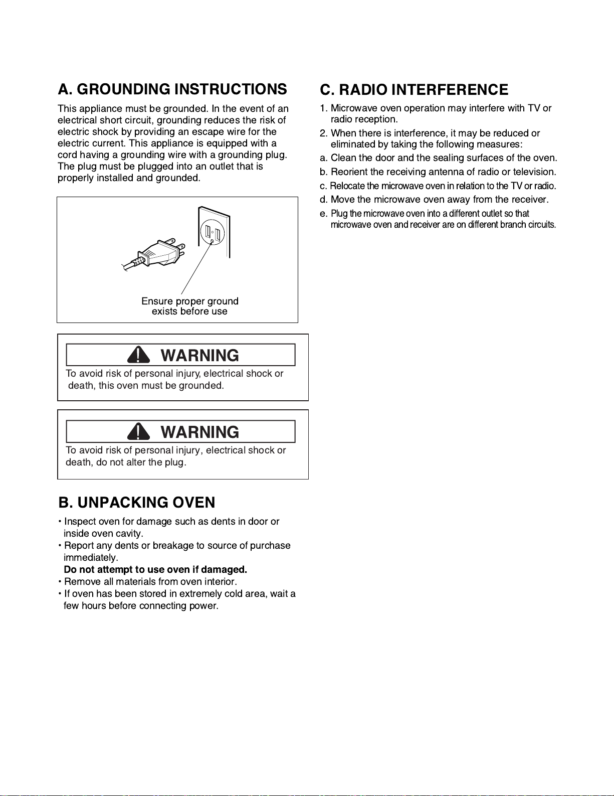
A. GROUNDING INSTRUCTIONS
This appliance must be grounded. In the event of an
electrical short circuit, grounding reduces the risk of
electric shock by providing an escape wire for the
electric current. This appliance is equipped with a
cord having a grounding wire with a grounding plug.
The plug must be plugged into an outlet that is
properly installed and grounded.
B. UNPACKING OVEN
¥ Inspect oven for damage such as dents in door or
inside oven cavity.
¥ Report any dents or breakage to source of purchase
immediately.
Do not attempt to use oven if damaged.
¥ Remove all materials from oven interior.
¥ If oven has been stored in extremely cold area, wait a
few hours before connecting power.
C. RADIO INTERFERENCE
1. Microwave oven operation may interfere with TV or
radio reception.
2. When there is interference, it may be reduced or
eliminated by taking the following measures:
a. Clean the door and the sealing surfaces of the oven.
b. Reorient the receiving antenna of radio or television.
c.
Relocate the microwave oven in relation to the TV or radio.
d. Move the microwave oven away from the receiver.
e.
Plug the microwave oven into a different outlet so that
microwave oven and receiver are on different branch circuits.
Ensure proper ground
exists before use
WARNING
!
To avoid risk of personal injury, electrical shock or
death, this oven must be grounded.
WARNING
!
To avoid risk of personal injury, electrical shock or
death, do not alter the plug.
- 7 -
INSTALLATION
Read this entire manual before you begin.
BEFORE YOU START
•
Proper installation is the installer's responsibility!
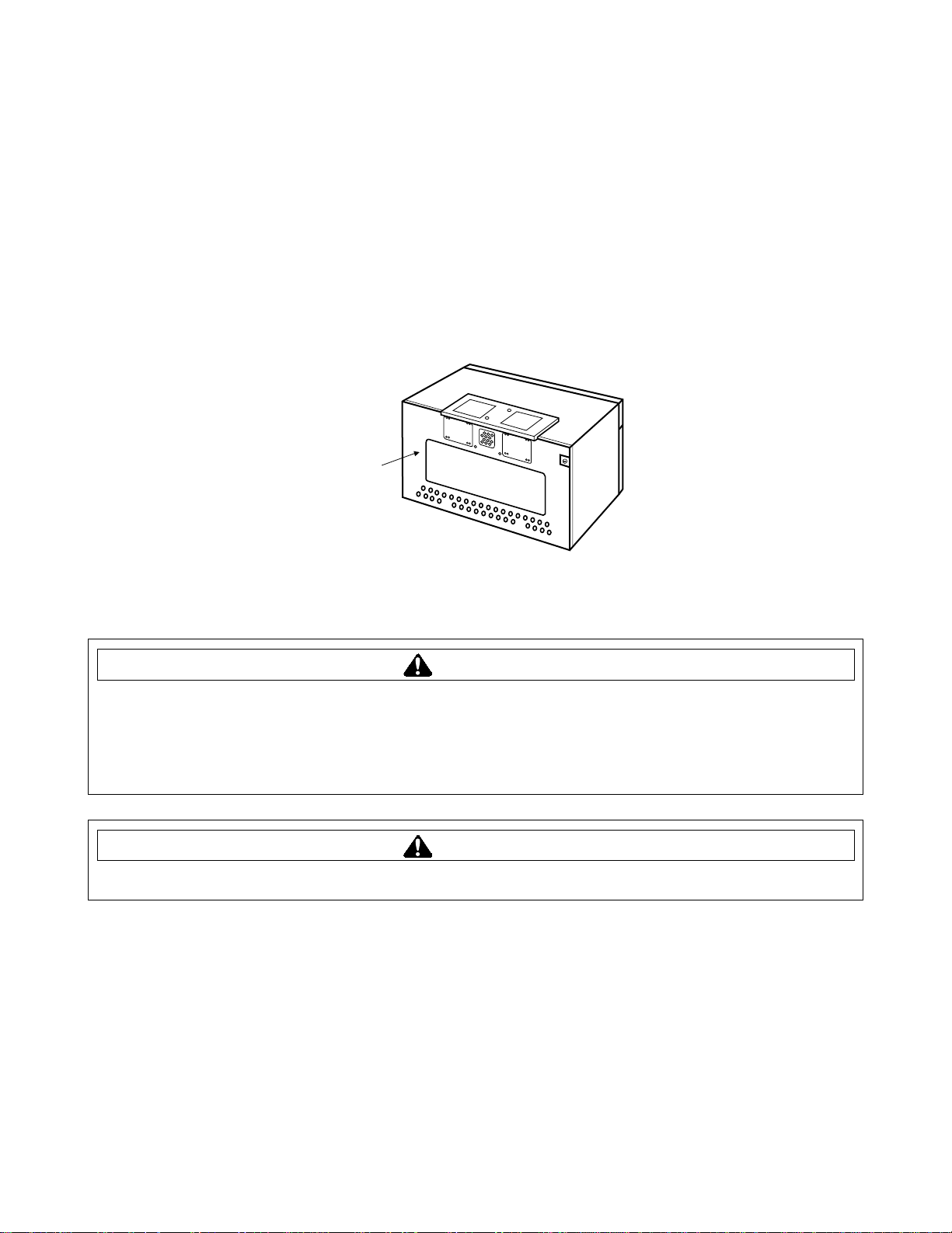
- Write the model & serial numbers on the owner’s manual. The model number label is located on the oven
front. The mounting plate is located on the back side of the microwave oven. See Figure 1.
BE SURE TO READ THE FOLLOWING SAFETY INSTRUCTIONS:
YOUR SAFETY FIRST
Mounting
plate
( Remove from
oven to install. )
Back of oven
Figure 1
To avoid risk of personal injury, electrical shock or death:
• Note where electrical outlets and electrical wires are before you drill into the wall.
• Locate and disconnect power to any electrical circuits that could be affected by installing this oven.
• Microwave must have a dedicated 120V, 60 Hz, AC, 15 or 20A fused electrical supply located in the cabinet
above the microwave, as close as possible to the microwave.
To avoid risk of personal injury or property damage, you will need two people to install this microwave oven.
WARNING
CAUTION
- 8 -
INSTALLATION
•
MAKE SURE YOU HAVE ENOUGH SPACE AND SUPPORT.
- Mount the oven against a flat, vertical wall, so it is supported by the wall. The wall should be constructed of
minimum 2" x 4" wood studding and 3/8" thick drywall or plaster/lath.
- ATTACH AT LEAST ONE of the two lag screws supporting the oven to a vertical, 2" x 4" wall stud.
- DO NOT mount the microwave oven to an island or peninsula cabinet.
- BE SURE the upper cabinet and rear wall structures are able to support 150 lbs., plus the weight of any
items you place inside the oven or upper cabinet.
- Locate the oven away from strong draft areas, such as windows, doors, and strong heating vents.
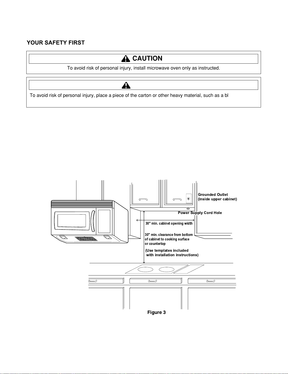
- BE SURE you have enough space. See Figure 3 below for minimum vertical and horizontal clearance.
- This microwave oven can be installed over gas or electric cooking products no more than 36 inches wide.
Figure 3
30" min. cabinet opening width
30" min. clearance from bottom
of cabinet to cooking surface
or countertop
(Use templates included
with installation instructions)
Grounded Outlet
(inside upper cabinet)
Power Supply Cord Hole
YOUR SAFETY FIRST
To avoid risk of personal injury, install microwave oven only as instructed.
To avoid risk of personal injury, place a piece of the carton or other heavy material, such as a blanket, over
the countertop or cooktop to protect it. DO NOT use a plastic cover.
CAUTION
CAUTION
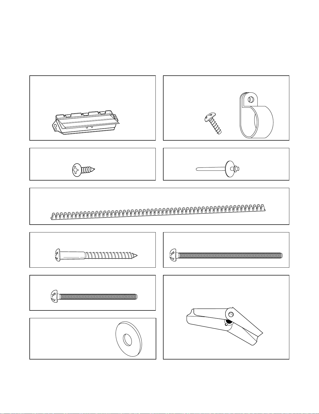
THE FOLLOWING PARTS ARE SUPPLIED WITH THE OVEN:
NOTE: Depending on your ventilation requirements, you may not use all of these parts.
NOTE: You need to install at least 2 lag screws into one 2" x 4" stud and four anchor bolts into the wall.
The mounting area must meet the 150 lbs. weight requirement.
- 9 -
Backdraft damper / duct connector
(for roof-venting or wall-venting installation)
Not Actual Size ( 2 pieces must be
assembled as shown )
INSTALLATION
PARTS, TOOLS, MATERIALS
Two self - tapping screws - Actual Size
(for attaching the damper duct connector)
One power cord clamp and
One dark-colored mounting screw
(to hold the power cord)
Actual Size
One lock pin and one washer-Not Actual size
One power cord clamp bushing - Actual Size
(for the cord hole in a metal upper cabinet)
Four 1/4" x 2" lag screws - Actual Size
(for wall stud holes)
Two 1/4" x 2" or 3" bolts - Actual Size
(for securing to the upper cabinet)
Two washers - Actual Size
(for the two upper cabinet bolts)
Four 1/4" x 3" toggle bolts - Actual Size
(for drywall holes)
Four spring toggle heads - Actual Size
(for the toggle bolts)
- 10 -
INSTALLATION
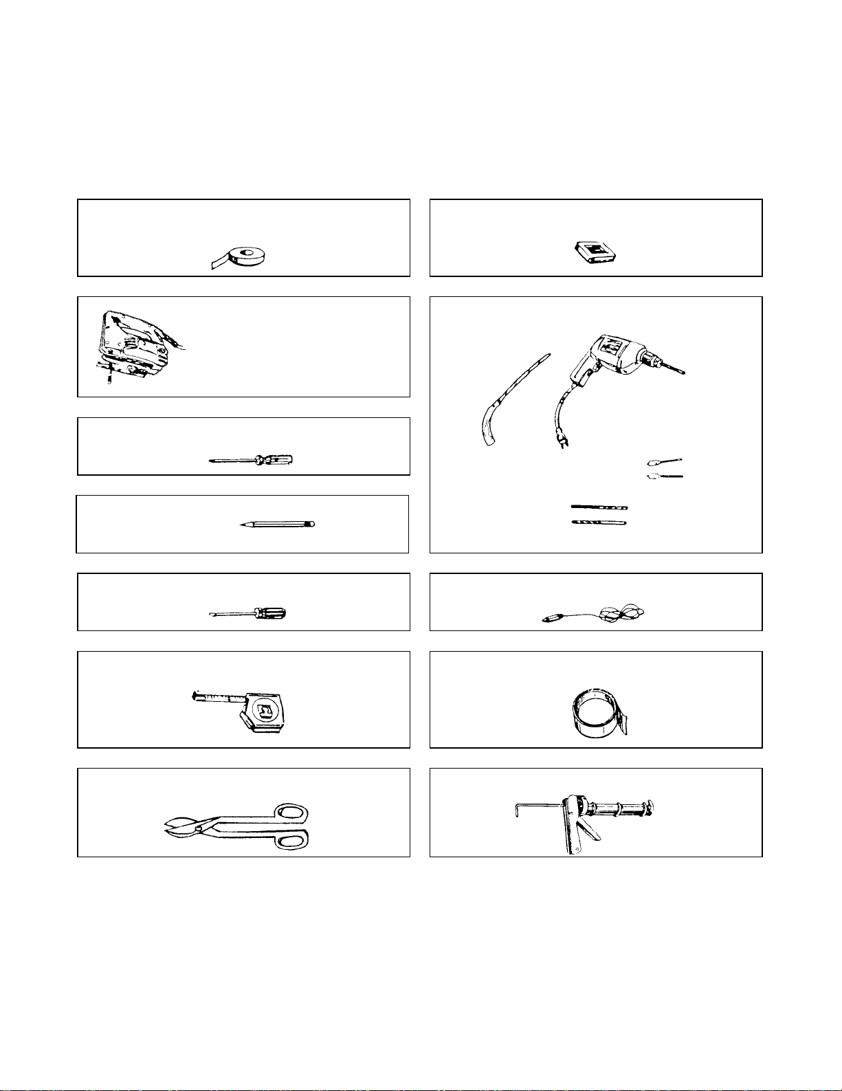
PARTS, TOOLS, MATERIALS
Clear tape
(for taping the templates to the wall)
Stud finder or thin nail.
Saber saw (for cutting vent
holes for roof or wall venting)
Keyhole saw (for the power cord hole)
Electric drill
3/8" and 3/4" wood drill bits
1/2" and 3/16"
drill bits
Phillips screwdriver (for the screws)
Pencil
Flat blade screwdriver (for the toggle bolts)
Measuring tape (metal preferred)
Small side cutters or tin snips Caulking gun
Plumb line
Duct Tape
YOU WILL NEED THE FOLLOWING TOOLS AND MATERIALS FOR THE INSTALLATION:
Carton or other heavy material for covering the counter top.
• If you have brick or masonry walls, you will need special hardware and tools.
• The ductwork you need for the installation is not included. All wall and roof caps must have a back-draft
damper.
- 11 -
INSTALLATION
STEP 1: PREPARE THE ELECTRICAL CONNECTIONS
•
DO NOT, UNDER ANY CIRCUMSTANCES, REMOVE THE POWER SUPPLY CORD GROUNDING
PRONG!
This appliance MUST be grounded!
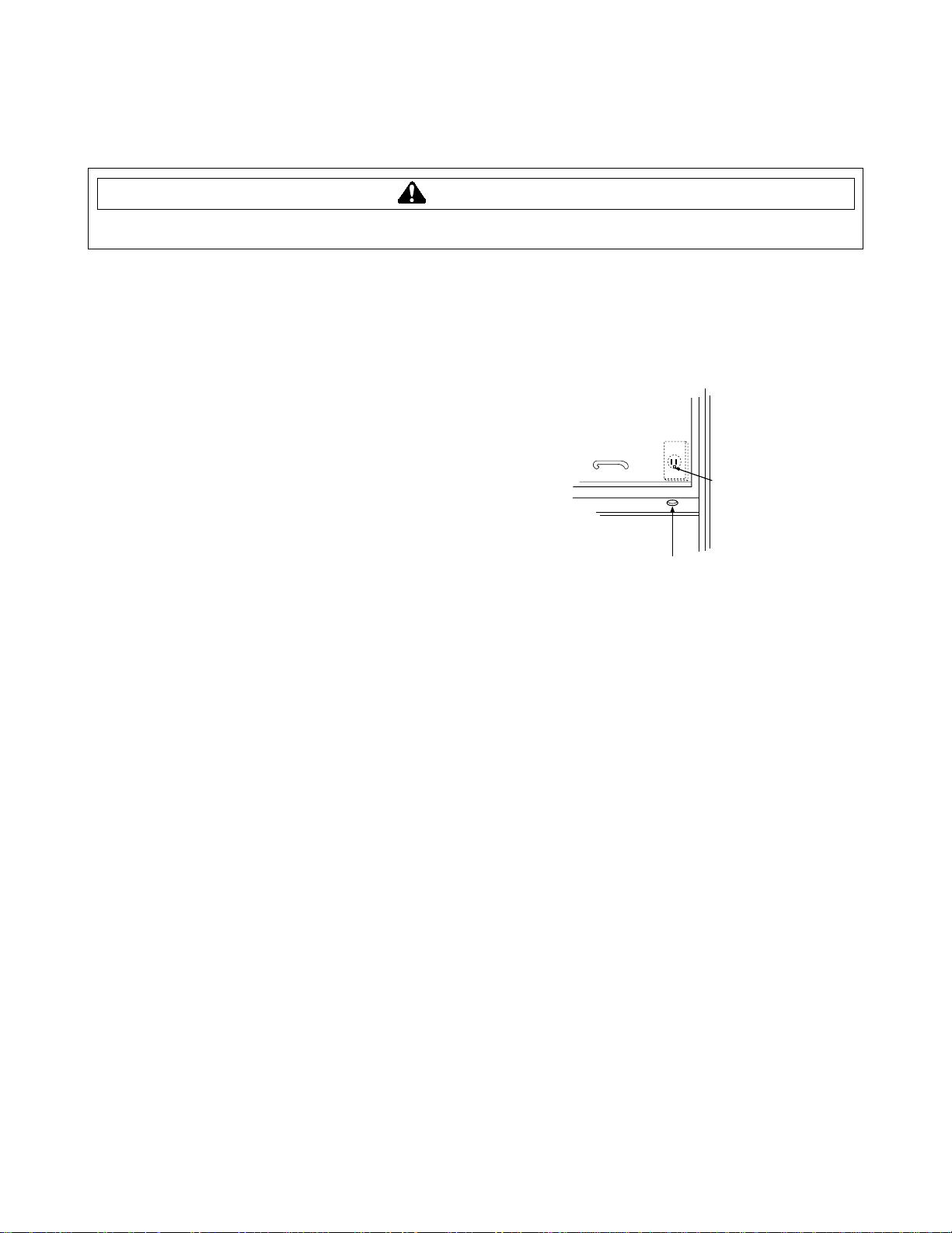
1. Locate the grounded electric outlet for this oven in the cabinet
above the oven, as shown in Figure 4.
NOTE: The outlet should be on a circuit dedicated to the
microwave oven (120V, 60Hz., AC only) with a
15 or 20A fused electrical supply.
IMPORTANT: If you do not have the proper wall outlet, you MUST
have one installed by a qualified electrician.
2. You will cut the power-supply-cord hole (shown in
Figure 4) later when you prepare the wall and upper cabinet in
Step 4.
NOTE: Do not use an extension cord.
Keep the power cord dry and do not pinch or crush it.
Grounded Outlet
( Inside Cabinet )
Upper
Cabinet
Power-Supply-Cord Hole
Figure 4
WARNING
To avoid risk of personal injury, electrical shock or death, this oven must be grounded.
WARNING
- 12 -
INSTALLATION
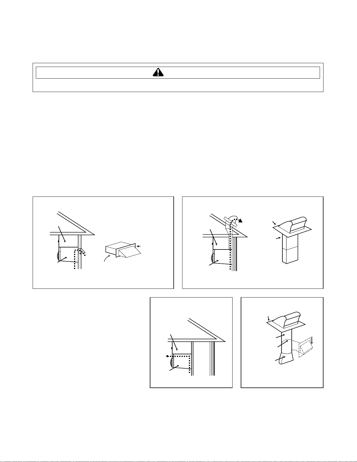
STEP 2: PREPARE THE VENTING SYSTEM
NOTE: The ductwork you need for outside ventilation is not included with your oven. The standard ductwork
fittings and length are shown in Figure 9.
You may vent your oven in one of three ways. However, do NOT vent into a wall cavity, an attic, or an unused area.
Roof-venting If your oven is located on an outside wall near the roof, as in Figures 6 (31/4" x 10" duct) and
Figure 8 (6" round duct.)
Wall-venting If your oven is located on an outside wall of your house, as in Figure 5 (31/4" x 10" duct) and
Figure 8 (6" round duct.)
Room-venting If your oven is located on an inside wall of your house, as in Figure 7.
NOTE: If you choose the rear exhaust method (roof-or wall-venting), be sure there is enough clearance within
the wall for the exhaust duct.
REMEMBER AS YOU INSTALL THE
VENTING:
• Keep the length of the ductwork and the
number of elbows to a minimum to
ventilate your oven efficiently.
See examples on next page.
• Keep the size of the ductwork the same.
• Do not install two elbows together.
• Use duct tape to seal all joints in the duct
system.
• Use caulking gun to seal the exterior wall
or roof opening around the cap.
Wall Venting
Wall venting
through-the-wall
wall cap
3 1/4"x10"
duct
Figure 5
cabinet
oven
To avoid risk of personal injury, property damage, or fire this microwave oven must be properly vented.
WARNING
cabinet
oven
cabinet
oven
Roof venting
Room Venting
Figure 7
Roof Venting
roof cap
3 1/4"x10"
duct
Figure 6
roof cap
6" min.
diameter
round duct
elbow
3 1/4" to round
duct transition
through-the-roof
3 1/4" to round
ductwork transition
Figure 8
wall cap
- 13 -
INSTALLATION
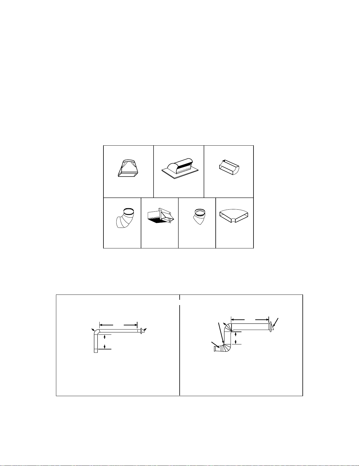
STEP 2: PREPARE THE VENTING SYSTEM
STANDARD FITTINGS
NOTE: If the existing duct is round, you must use a rectangular-to-round adapter, with a rectangular 3"
extension duct installed between the damper assembly and the adapter to prevent the exhaust
damper’s sticking.
DUCT LENGTH
The total length of the duct system, including straight duct, elbows, transitions, and wall or roof caps must not
exceed the equivalent of 140 feet.
For best performance, do not use more than three 90 degree elbows, and keep length as short as possible.
Below are the standard fittings and their equivalent length in feet.
To calculate the equivalent length of each ductpiece used, see the examples below.
Figure 9
1
4567
23
3 1/4"x10"
to 6"=5ft.
90˚ elbow
=10ft.
45˚ elbow
=5ft.
3 1/4"x10"
wall cap
=40ft.
3 1/4"x10"
flat elbow
=10ft.
3 1/4"x10" roof
cap=24ft.
3 1/4"x10" 90˚
elbow=25ft.
Examples
For 3 1/4"x10" SYSTEMS
1-3 1/4" x 10" 90˚ elbow
1-Wall Cap
8 feet straight duct
TOTAL LENGTH
1-transition
2-90˚ elbows
1-Wall Cap
8 feet straight
TOTAL LENGTH
For 6" ROUND SYSTEMS
6ft.
2ft.
2ft.
3 1/4"x10"
90˚ elbow
wall cap
6ft.
90˚ elbows
transition
wall cap
= 25 ft.
= 40 ft.
= 8 ft.
= 73 ft.
= 5 ft.
= 20 ft.
= 40 ft.
= 8 ft.
= 73 ft.
- 14 -
INSTALLATION
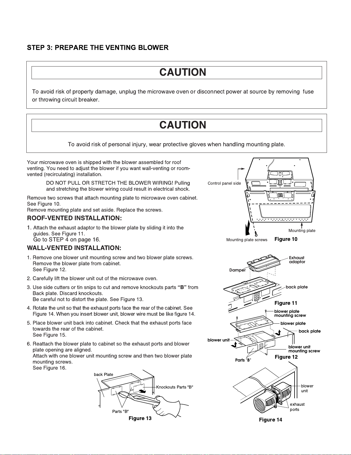
STEP 3: PREPARE THE VENTING BLOWER
Figure 10
Figure 11
Figure 12
Figure 14
Figure 13
Mounting plate
Mounting plate screws
Control panel side
Knockouts Parts "B"
Parts "B"
back Plate
blower
unit
exhaust
ports
back plate
Damper
Exhaust
adaptor
blower plate
mounting screw
blower unit
Parts "B"
back plate
blower plate
blower unit
mounting screw
To avoid risk of property damage, unplug the microwave oven or disconnect power at source by removing fuse
or throwing circuit breaker.
CAUTION
To avoid risk of personal injury, wear protective gloves when handling mounting plate.
CAUTION
Your microwave oven is shipped with the blower assembled for roof
venting. You need to adjust the blower if you want wall-venting or room-
vented (recirculating) installation.
DO NOT PULL OR STRETCH THE BLOWER WIRING! Pulling
and stretching the blower wiring could result in electrical shock.
Remove two screws that attach mounting plate to microwave oven cabinet.
See Figure 10.
Remove mounting plate and set aside. Replace the screws.
ROOF-VENTED INSTALLATION:
1. Attach the exhaust adaptor to the blower plate by sliding it into the
guides. See Figure 11.
Go to STEP 4 on page 16.
WALL-VENTED INSTALLATION:
1. Remove one blower unit mounting screw and two blower plate screws.
Remove the blower plate from cabinet.
See Figure 12.
2. Carefully lift the blower unit out of the microwave oven.
3. Use side cutters or tin snips to cut and remove knockouts parts
ÒBÓ
from
Back plate. Discard knockouts.
Be careful not to distort the plate. See Figure 13.
4. Rotate the unit so that the exhaust ports face the rear of the cabinet. See
Figure 14. When you insert blower unit, blower wire must be like figure 14.
5. Place blower unit back into cabinet. Check that the exhaust ports face
towards the rear of the cabinet.
See Figure 15.
6. Reattach the blower plate to cabinet so the exhaust ports and blower
plate opening are aligned.
Attach with one blower unit mounting screw and then two blower plate
mounting screws.
See Figure 16.
 Loading...