

LG UU09W INSTALLATION INSTRUCTIONS
INSTALLATION MANUAL
AIR
CONDITIONER
www.lg.com
High Efficiency Inverter
Original instruction
Please read this installation manual completely before installing the product.
Installation work must be performed in accordance with the national wiring
standards by authorized personnel only.
Please retain this installation manual for future reference after reading it thoroughly.
Ɠ This product contains Fluorinated Greenhouse Gases. (R410A)
[
Representative
] LG Electronics Inc. EU Representative : LG Electronics European Shared
Service Center B.V. Krijgsman 1, 1186 DM Amstelveen, The Netherlands
[Manufacturer] LG Electronics Inc. Changwon 2nd factory 84, Wanam-ro, Seongsan-gu,
Changwon-si, Gyeongsangnam-do, KOREA
P/NO : MFL67855401
ENGLISH
ITALIANO ESPAÑOL
FRANÇAIS
DEUTSCH
ΕΛΛΗΝΙΚΆ
ČEŠTINA
NEDERLANDS
POLSKI
LIMBA ROMÂNĂ

Air Conditioner Installation Manual
TABLE OF CONTENTS
Installation
Requirements
Safety Precautions .....3
Installation of Indoor,
Outdoor unit................7
The indoor unit
installation.................10
Remote controller
installation.................25
Wiring connection ....29
Connecting Pipes to
the Indoor Unit ..........31
Installation to
decorative panel .......33
Indoor unit drain
piping .........................34
Test running ..............41
Optional operation....43
Required Parts Required Tools
•
•
Connecting cable
• Four Type "A" Screw
• Hanging Bolt
(W 3/8 or M10 length 650mm)
• Pipes: Gas side
Liquid side
• Insulated drain hose
• Additional Drain hose
Inner Dia
Cassette type.............32mm
Duct type....................25mm
• Additional drain pipe
(Convertible type)
(Outer diameter .....15.5mm)
Level
•
Screw driver
•
Electric drill
•
Hole core drill (ø70mm)
• Flaring Tools set
• Torque Wrenches
• Hexagonal Wrench (4mm, 5mm)
• Gas-leak detector
•
Owner’s Manual
•
Thermometer
2
Safety Precautions
Safety Precautions
To prevent the injury of the user or other people and property damage, the following instructions
must be followed.
n Be sure to read before installing the air conditioner.
n Be sure to observe the cautions specified here as they include important items related to safety.
n Incorrect operation due to ignoring instruction will cause harm or damage. The seriousness is
classified by the following indications.
This symbol indicates the possibility of death or serious injury.
This symbol indicates the possibility of injury or damage to properties only.
n The meanings of the symbols used in this manual are as shown below.
Be sure not to do.
Be sure to follow the instruction.
n Installation
Always perform
grounding.
Don’t use a power
cord, a plug or a loose
socket which is damaged.
For installation of the
product, always contact the service center
or a professional installation agency.
ENGLISH
• Otherwise, it may cause
• Otherwise, it may cause
electrical shock.
Securely attach the
electrical part cover to
the indoor unit and the
service panel to the
outdoor unit.
• If the electrical part
• No installation may
cover of the indoor unit
and the service panel of
the outdoor unit are not
attached securely, it
could result in a fire or
electric shock due to
dust, water, etc.
a fire or electrical shock.
Always install an air
leakage breaker and a
dedicated switching
board.
cause a fire and
electrical shock.
• Otherwise, it may cause
a fire, electrical shock,
explosion or injury.
Do not keep or use
flammable gases or
combustibles near the
air conditioner.
• Otherwise, it may cause
a fire or the failure of
product.
Installation Manual 3
Safety Precautions
Ensure that an
installation frame of the
outdoor unit is not
Do not disassemble or
repair the product
randomly.
damaged due to use
for a long time.
• It may cause injury or an
accident.
• It will cause a fire or
electrical shock.
Use caution when unpacking and
installing.
• Sharp edges may cause injury.
n Operation
Do not share the outlet
with other appliances.
Do not use the
damaged power cord.
Do not install the
product at a place that
there is concern of
falling down.
• Otherwise, it may result
in personal injury.
Use a vacuum pump or Inert
(nitrogen) gas when doing leakage
test or air purge. Do not compress
air or Oxygen and Do not use
Flammable gases. Otherwise, it may
cause fire or explosion.
• There is the risk of death, injury, fire or
explosion.
Do not modify or
extend the power cord
randomly.
• It will cause an electric
• Otherwise, it may cause
shock or a fire due to
heat generation.
Take care so that the
power cord may not be
pulled during operation.
• Otherwise, it may cause
• Otherwise, it may cause
a fire or electrical shock.
4
• Otherwise, it may cause
a fire or electrical shock.
Unplug the unit if
a fire or electrical shock.
Keep the flames away.
strange sounds, smell,
or smoke comes from it.
• Otherwise, it may cause
electrical shock or a fire.
a fire.

Safety Precautions
Take the power plug
out if necessary,
holding the head of the
plug and do not touch
it with wet hands.
• Otherwise, it may cause
• Otherwise, it may cause
a fire or electrical shock.
Do not allow water to
run into electrical
parts.
• Otherwise, it may cause
• It may cause electric
the failure of machine or
electrical shock.
Do not step on the
indoor/outdoor unit
and do not put
anything on it.
• It may cause an injury
• Otherwise, it may cause
through dropping of the
unit or falling down.
Do not use the power
cord near the heating
tools.
a fire and electrical
shock.
Hold the plug by the
head when taking it
out.
shock and damage.
Do not place a heavy
object on the power
cord.
a fire or electrical shock.
Do not open the
suction inlet of the
indoor/outdoor unit
during operation.
• Otherwise, it may
electrical shock and
failure.
Never touch the metal
parts of the unit when
removing the filter.
• They are sharp and may
cause injury.
When the product is
submerged into water,
always contact the
service center.
• Otherwise, it may cause
a fire or electrical shock.
ENGLISH
Take care so that children may not step on the outdoor unit.
• Otherwise, children may be seriously injured due to falling down.
Installation Manual 5
Safety Precautions
n Installation
Install the drain hose to
ensure that drain can
be securely done.
Install the product so
that the noise or hot
wind from the outdoor
unit may not cause any
damage to the
neighbors.
• Otherwise, it may cause
water leakage.
• Otherwise, it may cause
dispute with the
neighbors.
Keep level parallel in installing the
product.
• Otherwise, it may cause vibration or
water leakage.
n Operation
Avoid excessive
cooling and perform
ventilation sometimes.
Use a soft cloth to
clean. Do not use wax,
thinner, or a strong
detergent.
Always inspect gas
leakage after the
installation and repair
of product.
• Otherwise, it may cause
the failure of product.
Please install safely at a place that
can sufficiently endure the weight of
the product.
• If the strength is not sufficient, the
product may fall and cause injury.
Do not use an
appliance for special
purposes such as
preserving animals
vegetables, precision
machine, or art articles.
• Otherwise, it may do
harm to your health.
• The appearance of the
air conditioner may
• Otherwise, it may
damage your properties.
deteriorate, change
color, or develop surface
flaws.
Do not place obstacles around the flow inlet or outlet.
• Otherwise, it may cause the failure of appliance or an accident.
6
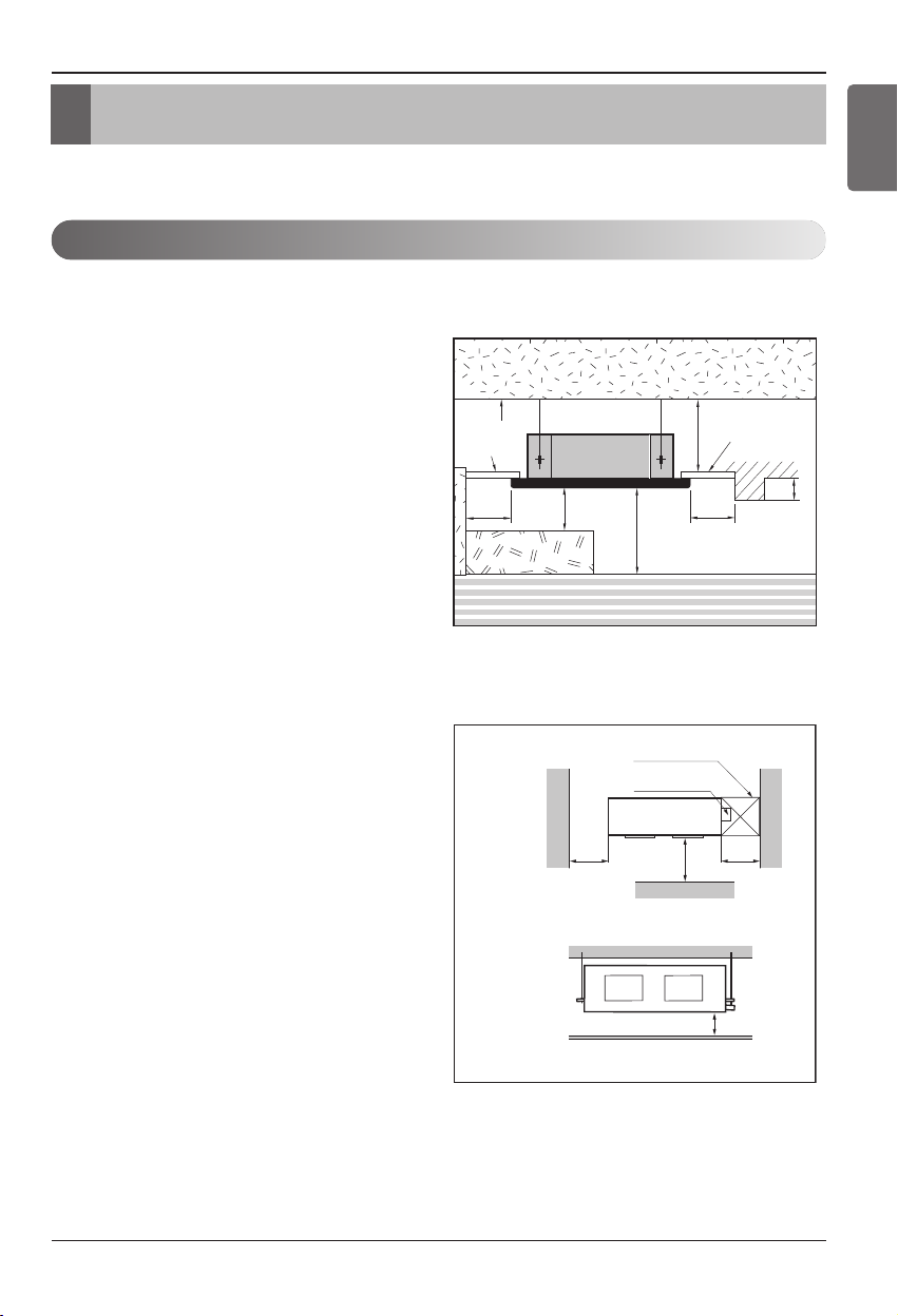
Installation of Indoor, Outdoor Unit
Unit:cm
Ceiling
Ceiling Board
Ceiling Board
30 or more
Above 250
330 or less
100
or more
50 or
more
50 or
more
30 or less
Floor
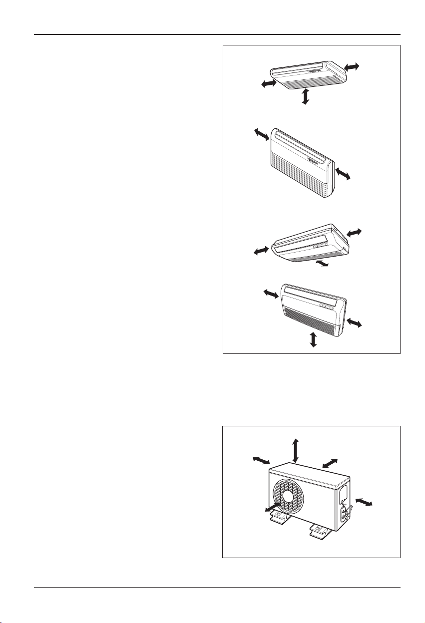
Installation of Indoor, Outdoor Unit
You need to select adequate installation location considering the following conditions, and make
sure to acquire the consent of the user.
Selection of the best location
1. Indoor unit
Cassette type
• There should not be any heat source or steam
near the unit.
• There should not be any obstacles to prevent
the air circulation.
• A place where air circulation in the room will
be good.
•
A place where drainage can be easily obtained.
• A place where noise prevention is taken into
consideration.
• Do not install the unit near the door way.
• Ensure the spaces indicated by arrows from
the wall, ceiling, or other obstacles.
• The indoor unit must keep the maintenance
space.
ENGLISH
Duct type
• The place shall easily bear a load exceeding
four times the indoor unit’s weight.
• The place shall be able to inspect the unit as
shown the figure.
• The place where the unit shall be leveled.
• The place shall allow easy water
drainage.(Suitable dimension “H” is necessary
to get a slope to drain as figure.)
• The place shall easily connect with the
outdoor unit.
• The place where the unit is not affected by an
electrical noise.
• The place where air circulation in the room will
be good .
• There should not be any heat source or steam
near the unit
Top view
(unit: mm)
Front view
Inspection hole
(600X600)
Control box
600600
1000
Front
H
Installation Manual 7
Installation of Indoor, Outdoor Unit
Convertible type
• Do not have any heat or steam near the unit.
• Select a place where there are no obstacles in
front of the unit.
• Make sure that condensation drainage can be
conveniently routed away.
• Do not install near a doorway.
• Ensure that the interval between a wall and
the left (or right) of the unit is more than
20cm.
• Use a stud finder to locate studs to prevent
unnecessary damage to the wall.
• There should not be any heat source or steam
near the unit.
• There should not be any obstacles to prevent
the air circulation.
• A place where air circulation in the room will
be good.
• A place where drainage can be easily
obtained.
• A place where noise prevention is taken into
consideration.
• Do not install the unit near the door way.
• Ensure the spaces indicated by arrows from
the wall, ceiling, or other obstacles.
More than
20cm
More than eye-level
(Ceiling installation)
More than
20cm
(Floor/Wall installation)
More than 20cm
More than 20cm
More than
R
More than
R
More than 20cm
More than 5cm
20cm
20cm
More than 5cm
More than 20cm
2. Outdoor unit
•
If an awning is built over the unit to prevent direct sunlight or rain exposure, make sure that heat
radiation from the condenser is not restricted.
• Ensure that the spaces indicated by arrows around front, back and side of the unit.
• Do not place animals and plants in the path of the warm air.
•
Take the air conditioner weight into account and
select a place where noise and vibration are
minimum.
•
Select a place so that the warm air and noise
from the air conditioner do not disturb neighbors.
• Place that can sufficiently endure the weight
and vibration of the outdoor unit and where
even installation is possible.
• Place that has no direct influence of snow or rain
• Place with no danger of snowfall or icicle drop
• Place without weak floor or base such as
decrepit part of the building or with a lot of snow
accumulation
8
More than
30cm
More than
70cm
More than 60cm
More than 30cm
More
than 60cm
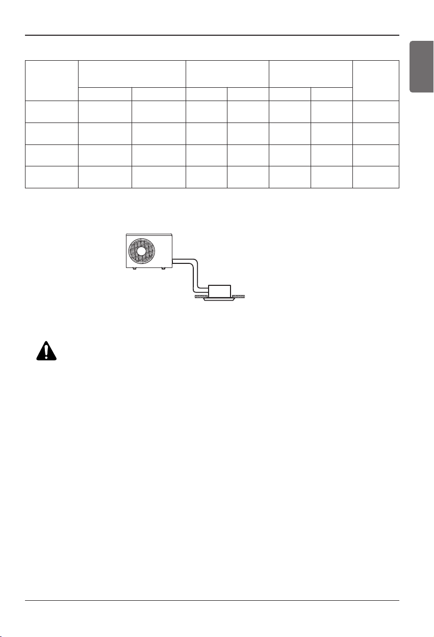
Installation of Indoor, Outdoor Unit
Outdoor unit
Indoor unit
A trap is not necessary when the
outdoor unit is installed in a higher
position than the indoor unit.
3. Piping length and the elevation
MODEL
AUUW096D
[UU09W ULD]
AUUW126D
[UU12W ULD]
AUUW186D
[UU18W UED]
AUUW186D1
[UU18W UED1]
Pipe Size (Diameter:Ø) Length A(m) Elevation B(m)
Gas Liquid Standard Max. Standard Max.
3/8"(9.52mm) 1/4"(6.35mm) 7.5 15 5 10 20
3/8"(9.52mm) 1/4"(6.35mm) 7.5 15 5 10 20
1/2"(12.7mm) 1/4"(6.35mm) 7.5 40 5 30 20
1/2"(12.7mm) 1/4"(6.35mm) 5.0 40 5 30 20
ENGLISH
*Additional
refrigerant
(g/m)
CAUTION:
• Rated performance for refrigerant line length of:7.5m (AUUW096D, AUUW126D,
AUUW186D) / 5.0m (AUUW186D1)
• Capacity is based on standard length and maximum allowance length is on the
basis of reliability.
• Improper refrigerant charge may result in abnormal cycle.
Installation Manual 9
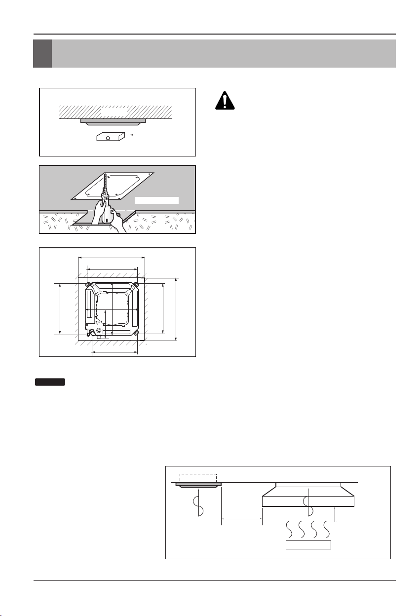
The indoor unit installation
The indoor unit installation
1. Cassette type
CAUTION :
Ceiling
Level gauge
• This air-conditioner uses a drain
pump.
• Install the unit horizontally using a
level gauge.
During the installation, care should be
•
taken not to damage electric wires.
Ceiling board
• Select and mark the position for fixing bolts and piping
hole.
• Decide the position for fixing bolts slightly tilted to the
drain direction after considering the direction of drain
hose.
• Drill the hole for anchor bolt on the wall.
NOTICE
523
TQ/TR Series
585~660
517
570
570
319
461
517
Unit: mm
585~660
• Avoid the following installation location.
1. Such places as restaurants and kitchen where considerable amount of oil steam and flour is generated.
These may cause heat exchange efficiency reduction, or water drops, drain pump mal-function.
In these cases, take the following actions;
• Make sure that ventilation fan is enough to cover all noxious gases from this place.
• Ensure enough distance from the cooking room to install the air conditioner in such a place where it
may not suck oily steam.
2. Avoid installng air conditioner
in such places where
Air conditioner
cooking oil or iron powder is
generated.
3. Avoid places where
inflammable gas is generated.
4. Avoid place where noxious gas is
generated.
Take enough
distance
Cooking table
Use the ventilation fan
for smoke-collecting
hood with sufficient
capacity.
5. Avoid places near high frequency
generators.
10
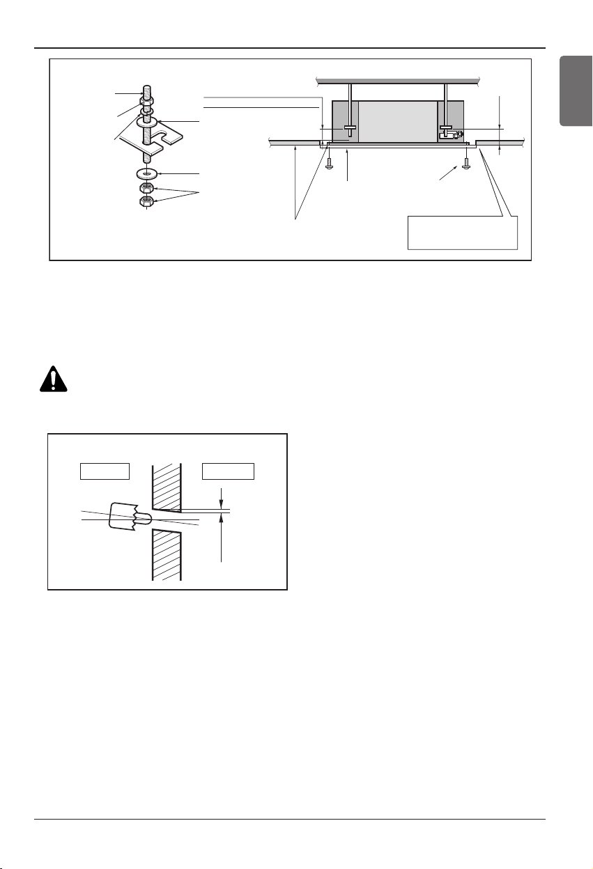
Wall
5~7mm
Indoor Outdoor
Set screw of
paper model (4 pieces)
Paper model
for installation
Ceiling board
150mm
Adjust the same height
Ceiling board
Ceiling
Flat washer for M10
(accessory)
Keep the length of the bolt
from the bracket to 40mm
Open the ceiling board
along the outer edge of the
paper model
Flat washer for M10
(accessory)
Hanging bolt
(W3/8 or M10)
Nut
(W3/8 or M10)
Nut
(W3/8 or M10)
Spring washer
(M10)
Air Conditioner body
• The following parts is option.
① Hanging Bolt - W 3/8 or M10
② Nut - W 3/8 or M10
③ Spring Washer - M10
④ Plate Washer - M10
The indoor unit installation
ENGLISH
CAUTION:
Tighten the nut and bolt to prevent unit falling.
• Drill the piping hole on the wall slightly tilted to the outdoor side using a Ø 70 hole-core drill.
Installation Manual 11
The Indoor Unit Installation
Drainage hole
M10 Nut
M10 SP. washer
M10 washer
X 4
X 4
(Local
supply)
X 4
M10 Nut
M10 SP. washer
M10 washer
X 4
X 4
(Local
supply)
X 4
A
B
CD
(G)
H
I
EF
1~3mm
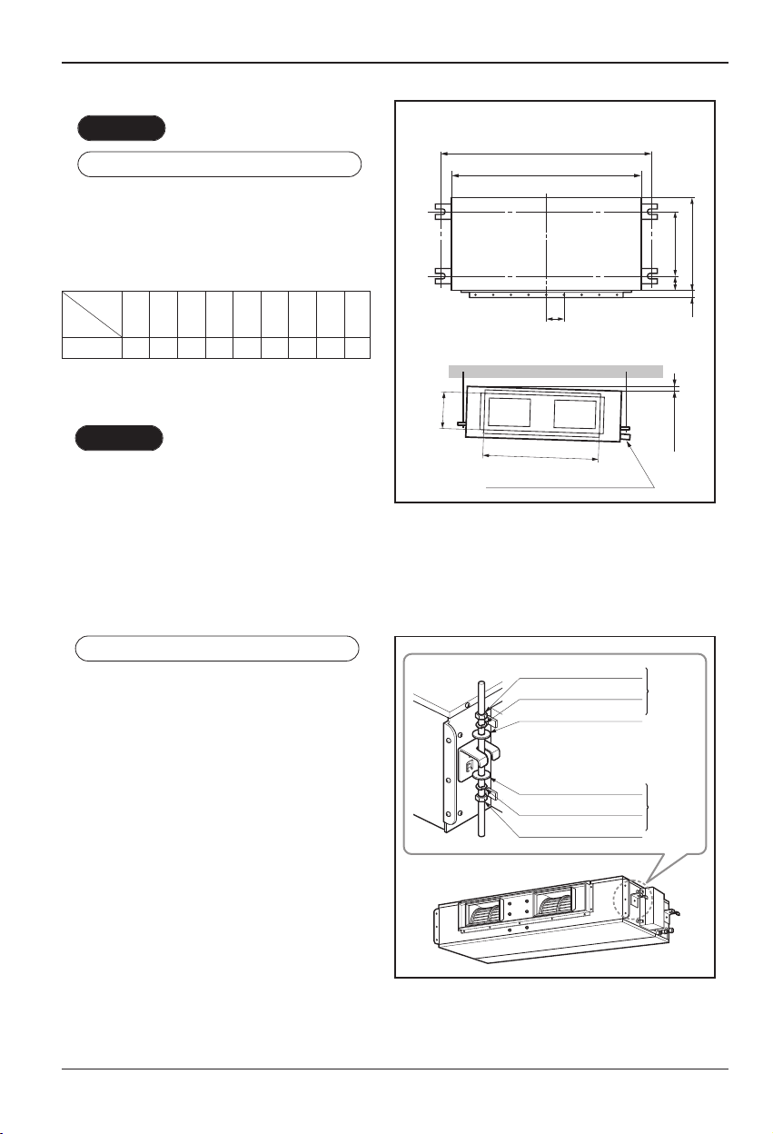
2. Duct type
CASE 1
POSITION OF SUSPENSION BOLT
• Apply a joint-canvas between the unit and
duct to absorb unnecessary vibration.
• Apply a filter Accessory at air return hole.
(Unit:mm)
Dimension
Capacity
18k Btu/h 932 880 355 45.5 450 30 87 750 163
ABCDEF(G)HI
CASE 2
• Install the unit leaning to a drainage hole
side as a figure for easy water drainage.
POSITION OF CONSOLE BOLT
• A place where the unit will be leveled and
that can support the weight of the unit.
• A place where the unit can withstand its
vibration.
• A place where service can be easily
performed.
12
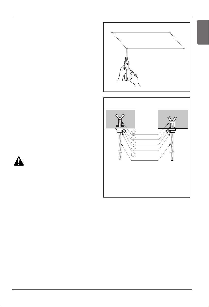
The Indoor Unit Installation
• Select and mark the position for fixing
bolts.
• Drill the hole for set anchor on the face
of ceiling.
• Insert the set anchor and washer onto
the suspension bolts for locking the
suspension bolts on the ceiling.
• Mount the suspension bolts to the set
anchor firmly.
• Secure the installation plates onto the
suspension bolts (adjust level roughly)
using nuts, washers and spring
washers.
CAUTION:
Tighten the nut and bolt
to prevent unit falling.
Old building New building
1 Set anchor
2 Plate washer
3 Spring washer
4 Nut
5 Suspension
bolts
• Local supply
① Set anchor
② Plate washer - M10
③ Spring washer - M10
④ Nut - W3/8 or M10
⑤ Suspension bolt - W3/8 or M10
ENGLISH
Installation Manual 13
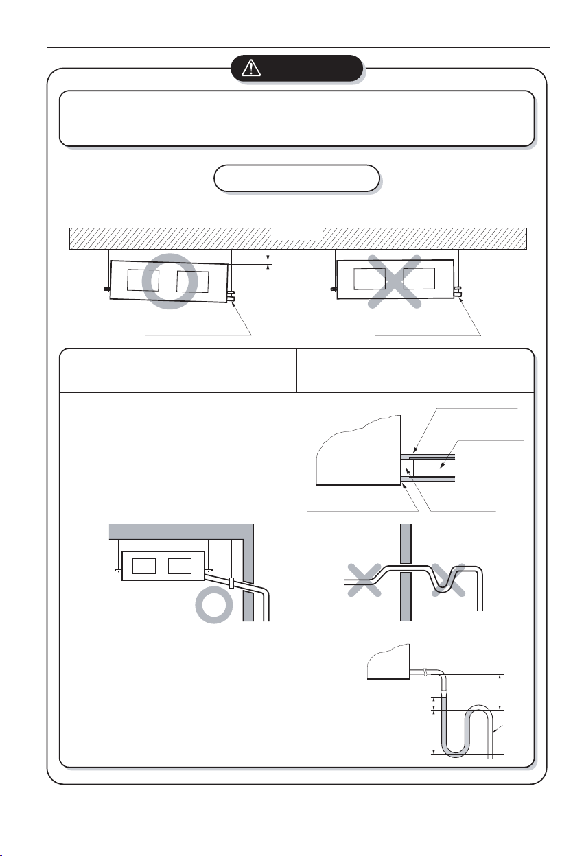
The Indoor Unit Installation
CAUTION
1. Install declination of the indoor unit is very important for the drain of the duct type air
conditioner.
2. Minimum thickness of the insulation for the connecting pipe shall be 5mm.
Front of view
• The unit must be declined to the drain hose connected when finished
Ceiling
1~3mm
CORRECT
Drainage hole
CAUTION FOR GRADIENT OF
UNIT AND DRAIN PIPING
• Always lay the drain with downward
inclination (1/50 to 1/100).
Prevent any upward flow or reverse flow
in any part.
• 10mm or thicker formed thermal insulator
shall always be provided for the drain
pipe.
INCORRECT
Drainage hole
Lay the drain hose with a downward
inclination so water will drain out.
Unit
Make sure to be closed.
• Upward routing not
allowed
installation.
Thermal insulator
(Local supply)
Drainage pipe
(Local supply)
Drainage hole
CORRECT
• Install the P-Trap (or U-Trap) to prevent
a water leakage caused by the blocking
of intake air filter.
14
INCORRECT
Applied U-Trap Dimension
≥
A 70mm
≥
B 2C
≥
C 2 x SP
SP = External Pressure
(mmAq)
Ex) External Pressure
= 10mmAq
≥
A 70mm
≥
B 40mm
≥
C 20mm
C
A
B
U-Trap
The Indoor Unit Installation
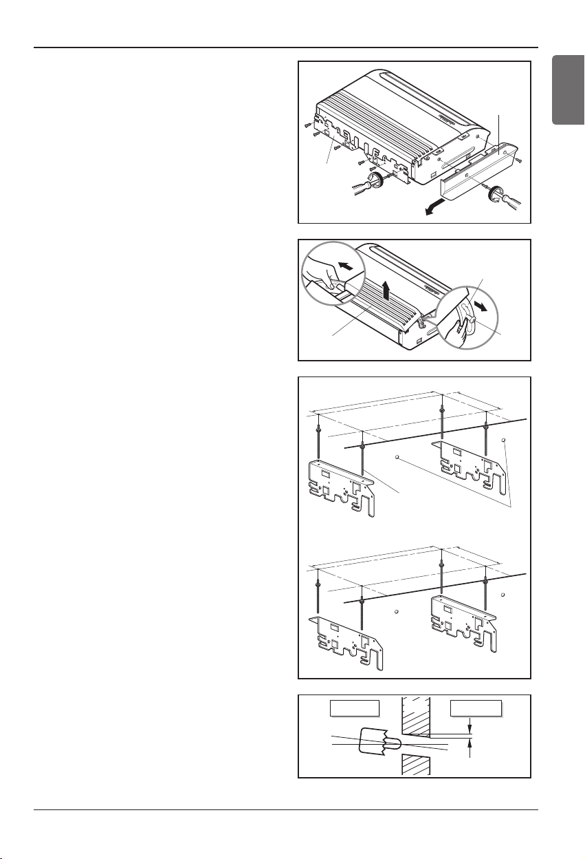
3. Convertible type(18k Btu/h)
n
Before Installing, prepare Installation Plates
• 'Installation Plates' are attached at the bottom
of indoor unit.
Detach them by removing each 3 screws at
both sides.
• Detach 'Side Plate (R,L)' by removing each 2
screws on both sides.
• Pull the upper right and left side of 'Inlet Grille'
to the front, and it will stop at slightly tilted
position.
• Unhook the 'Inlet hanger' from the 'Hanger
screw' on the both left and right side.
• Detach the 'Inlet Grille' from the Indoor Unit.
1) Installation on the ceiling
• Measure and mark the position for the
Suspension bolts and the piping hole.
• Drill the hole for anchor nut on the ceiling.
※ Before secure the Installation Plates,
select the bent direction of the
Installion Plate to the inside or the
outside according to the installation
circumstances.
Install Plate
Inlet Grille
1)
1076
Suspension
bolt
Center-line for the
ENGLISH
Side Plate
Inlet hanger
Hanger
screw
265
piping hole
• Drill the piping hole on the wall slightly tilted
to the outdoor side using a ø70 hole-core
drill.
2)
1236
Indoor Outdoor
WALL
265
5~7mm
Installation Manual 15
 Loading...