

LG tx Service Manual

Service Manual
(TX)
LG Electronics
0

Contents
Ch 1. Service information
Ch 2. Locations
Ch 3. System information
· Specification
· System Block Diagram
· Fn key combinations
· Status indicators
· BIOS Flash
· BIOS Setup
Ch 4. Symptom-to-part index
· Power system checkout
· Numeric error codes
· Error messages
· LCD-related symptoms
· Indeterminate problems
Ch 5. Removing and replacing a part (FRU)
Ch 6. Part list
· Part list
· Exploded view
1
Ch1. Service information
Chapter 1. Service information
1-1. Important service information
Strategy for replacing parts (FRU-Field Replaceable Units)
Before replacing parts
Make sure that latest BIOS and drivers are installed before replacing any parts (FRUs) listed in this
Use the following strategy to prevent unnecessary expense for replacing and servicing parts
1. If you are instructed to replacing a part but the replacement does not correct the problem, reinstall the
original part before you continue.
2. Some computers have both a processor board and system board. If you are instructed to replace either
the processor board or the system board, and replacing one of them does not correct the problem,
reinstall that board, and then replace the other one.
3. If an adapter or device consists of more than one part, any of the parts (FRUs) may be the cause of the
error. Before replacing the adapter or device, remove the parts (FRUs), one by one, to see if the
symptoms change. Replace only the part that changed the symptoms.
Caution
The BIOS configuration on the computer you are servicing may have been customized.
Running Automatic Configuration my alter the settings. Note the current configuration settings;
then, when service has been completed, verify that those settings remain in effect.
Strategy for replacing a hard-disk drive
You have to get a User’s approval before formatting or replacing a hard-disk drive. You must let the User
know that the user is responsible for the loss data
Caution
The drive startup sequence in the computer you are servicing may have been changed. Be
extremely careful during write operations such as copying, saving, or formatting. If you select an
incorrect drive, data or programs can be overwritten.
2
1-2. Safety notices
Warning
Before the computer is powered-on after part (FRU) replacement, make sure all screws, springs,
and other small parts are in place and are not left loose inside the computer. Verify this by
shaking the computer and listening for rattling sounds. Metallic parts or metal flakes can cause
electrical shorts.
Warning
some standby batteries contain a small amount of nickel and cadmium. Do not disassemble
a standby battery, recharge it, throw it into fire or water, or short-circuit it. Dispose of the battery
as required by local ordinances or regulations. Use only the battery in the appropriate parts
listing. Use of an incorrect battery can result in ignition or explosion of the battery
Warning
Ch1. Service information
The battery pack contains small amounts of nickel. Do not disassemble it, throw it into fire or
water, or short-circuit it. Dispose of the battery pack as required by local ordinances or
regulations. Use only the battery in the appropriate parts listing when replacing the battery pack.
Use of an incorrect battery can result in ignition or explosion of the battery.
Warning
If the LCD breaks and the fluid from inside the LCD gets into your eyes or on your hands,
immediately was the affected areas with water for at least 15 minutes. Seek medical care if any
symptoms from the fluid are present after washing.
Warning
To avoid shock, do not remove the plastic cover that protects the lower part of the inverter card.
Warning
Though the main batteries have low voltage, a shorted or grounded battery can produce enough
current to burn personnel or combustible materials.
Warning
Before removing any part (FRU), turn off the computer, unplug all power cords from electrical
outlets, remove the battery pack, and then disconnect any interconnecting cables.
3

Ch1. Service information
1-3. Safety information
General safety
Follow these rules to ensure general safety
· Observe good housekeeping in the area of the machines during and after maintenance.
· When lifting any heavy object
1. Ensure you can stand safely without slipping.
2. Distribute the weight of the object equally between your feet.
3. Use a slow lifting force. Never move suddenly or twist when you attempt to lift.
4. Lift by standing or by pushing up with your leg muscles
(This action removes the strain from the muscles in your back.)
· Do not attempt to lift any object weights more then 16kg(35lb) or object that you think are too heavy for you.
· Do not perform any action that causes hazards to the customer, or that makes the equipment unsafe.
· Before you start the machine, ensure that other service representatives and the customer’s personnel are
not in a hazardous position.
· Place removed covers and other parts in a safe place, away from all personnel, while you are servicing the
machine.
· Keep your tool box away from walk areas so that other people will not trip over it.
· Do not wear loose clothing that can be trapped in the moving parts of a machine. Make sure that your
sleeves are fastened or rolled up above your elbows. If your hair is long, fasten it.
· Insert the ends of your necktie or scarf inside clothing or fasten it with a nonconductive clip, approximately
8 centimeters(3 inches) from the end.
· Do not wear jewelry, chains, metal-frame eyeglasses, or metal fasteners for you clothing.
· Wear safety glasses when you are hammering, drilling, soldering, cutting wire, attaching springs, using
solvents, or working in any other conditions that might be hazardous to your eyes.
· After service, reinstall all safety shields, guards, labels, and ground wires. Replace any safety device that
is worn or defective.
· Reinstall all covers correctly before returning the machine to the customer.
Caution
Metal objects are good electrical conductors.
4
Ch1. Service information
Electrical safety
Observe the following rules when working on electrical equipment.
Important
Use only approved tools and test equipment. Some hand tools have handles covered with a soft
material that does not insulate you when working with live electrical currents.
Many customers have, near their equipment, rubber floor mats that contain small conductive
fibers to decrease electrostatic discharges. Do not use this type of mat to protect yourself from
electrical shock.
· Find the room emergency power-off switch, disconnecting switch, or electrical outlet. If an electrical outlet.
If an electrical accident occurs, you can then operate the switch or unplug the power cord quickly.
· Do not work alone under hazardous conditions or near equipment that has hazardous voltages.
· Disconnect all power before
1. Performing a mechanical inspection
2. Working near power supplies
3. Removing or installing main units
· Before you start to work on the machine, unplug the power cord. If you cannot unplug it, ask the customer
to power-off the wall box that supplies power to the machine and to lock the wall box in the off position.
· If you need to work on a machine that has exposed electrical circuits, observe the following precautions :
Ensure that another person, familiar with the power-off controls, is near you.
Caution
Another person must be there to switch off the power, if necessary.
· Use only one hand when working with powered-on electrical equipment. Keep the other hand in your
pocket or behind your back
Caution
An electrical shock can occur only when there is a complete circuit. By observing the above rule,
you may prevent a current from through your body.
· When using testers, set the controls correctly and use the approved probe leads and accessories for that
tester
5

Ch1. Service information
· Stand on suitable rubber mats (obtained locally, if necessary) to insulate you from grounds such as metal
floor strips and machine frames.
· Observe the special safety precautions when you work with very high voltages. These instructions are in
the safety sections of maintenance information. Use extreme care when measuring high voltages.
· Regularly inspect and maintain your electrical hand tools for safe operational condition.
· Do not use worn or broken tools and testers.
· Never assume that power has been disconnected from a circuit. First check that it has been powered off.
· Always look carefully for possible hazards in your work area. Examples of these hazards are moist floors,
non-grounded power extension cables, power surges, and missing safety grounds.
· Do not touch live electrical circuits with the reflective surface of a plastic dental mirror. The surface is
conductive such touching can cause personal injury and machine damage.
· Do not service the following parts with the power on when they are removed from their normal operating
places in a machine.
1. Power supply units
2. Pumps
3. Blowers and fans
4. Motorgenerators
and similar units. (This practice ensure correct grounding of the units.)
· If an electrical accident occurs
1. Use caution ; do not become a victim of yourself.
2. Switch off power.
3. Send another person to get medical aid.
6

Ch1. Service information
Safety inspection guide
The purpose of this inspection guide is to assist you in identifying potentially unsafe conditions.
As each machine was designed and built, required safety items were installed to protect users and service
personnel from injury. This guide addresses only those items. You should use good judgment to identify
potential safety hazards due to attachment of non-LG features or options not covered by this inspection
guide.
If any unsafe conditions are present, you must determine how serious the apparent hazard could be and
whether you can continue without first correcting the problem.
· Consider these conditions and the safety hazards they present
1. Electrical hazards, especially primary power (primary voltage on the frame can cause serious or fatal
electrical shock)
2. Mechanical hazards, such as loose or missing hardware
Refer to the following checklist and begin the checks with the power off, and the power cord disconnected.
· Checklist
1. Check exterior covers for damage (loose, broken, or sharp edges)
2. Power off the computer. Disconnect the power cord.
3. Check the power cord for :
a. A third-wire ground connector in good condition. Use a meter to measure third-wire ground continuity
for 0.1 or less between the external ground pin and frame ground.
b. The power cord should be the type specified in the parts list.
c. Insulation must not be frayed or worn.
4. Remove the cover.
5. Check for any obvious non-LG alterations. Use good judgment as to the safety of any non-LG
alterations.
6. Check inside the unit for any obvious unsafe conditions, such as metal filings, contamination, water or
other liquids, or signs of fire or smoke damage.
7. Check for worn, frayed, or pinched cables.
8. Check that the power-supply cover fasteners (screw or rivets) have not been removed or tampered with.
7

Ch1. Service information
Handling devices that are sensitive to electrostatic discharge
Any computer part containing transistors or integrated circuits (ICs) should be considered sensitive to
electrostatic discharge (ESD). ESD damage can occur when there is a difference in charge between
objects. Protect against ESD damage by equalizing the charge so that the machine, the part, the work mat,
and the person handling the part are all at the same charge.
Note
Use product-specific ESD procedures when they exceed the requirements noted here.
Make sure that the ESD protective devices you use have been certified (ISO9000) as fully effective.
· When handling ESD-sensitive parts :
1. Keep the parts in protective packages until they are inserted into the product.
2. Wear a grounded wrist strap against your skin to eliminate static on your body.
3. Prevent the part from touching your clothing. Most clothing retains a charge even when you are wearing
a wrist strap.
4. Use the black side of a grounded work mat to provide a static-free work surface. The mat is especially
useful when handling ESD-sensitive devices.
5. Select a grounding system, such as those listed below, to provide protection that meets the specific
service requirement.
Note
The use of a grounding system is desirable but not required to protect against ESD damage.
a. Attach the ESD ground clip too any frame ground, ground braid, or green-wire ground.
b. Use an ESD ground or reference point when working on a double-insulated or battery-operated
system. You can use coax or connector-outside shells on these systems.
c. Use the round ground-prong of the AC plug on AC-operated computers.
Grounding requirements
Electrical grounding of the computers is required for operator safety and correct system function.
Proper grounding of the electrical outlet can be verified by a certified electrician.
8
Ch1. Service information
1-4. Laser compliance statement
When a CD-ROM drive, DVD drive or the other laser product is installed, note the following :
Caution
Use of controls or adjustments or performance of procedures other than those specified here in
might result in hazardous radiation exposure.
Opening the CD-ROM drive, DVD-ROM drive or the other optical storage device could result in exposure
to hazardous laser radiation.
There are no serviceable parts inside those drives. Do not open
Danger
Emits visible and invisible laser radiation when open. Do not stare into the beam , do not view
directly with optical instruments, and avoid direct exposure to the bean.
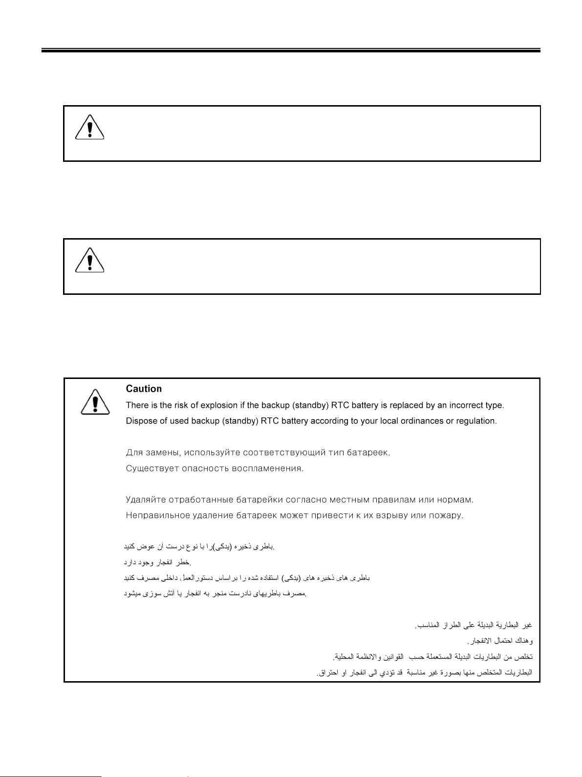
1-5. Backup (Standby) RTC battery safety information
When replacing or disposing of the backup (standby) RTC battery, note the following :
9

Ch1. Service information
1-6. Read this first
Before you go to the checkout guide, be sure to read this section.
Important Notes
· Only trained personnel certified by LG should service the computer.
· Read the entire FRU removal and replacement page before replacing any FRU.
· Use new nylon-coated screws when you replace FRUs.
· Be extremely careful during such write operations as copying, saving, formatting.
Drives in the computer that you are servicing sequence might have been altered. If you selected an
incorrect drive, data or programs might be overwritten.
· Replace FRUs only for the correct mode.
· When you replace a FRU, make sure the model of the machine and the FRU part number are correct by
referring to the FRU parts list.
· A FRU should not be replaced because of a single, irreproducible failure. Single failures can occur for a
variety of reasons that have nothing to do with a hard ware defect, such as cosmic radiation,
electrostatic discharge, or software errors.
· Consider replacing a FRU only when a problem recurs. If you suspect that a FRU is defective, clear the
error log and run the test again. If the error does not recur, do not replace the FRU.
· Be careful not to replace a non-defective FRU.
What to do first
You must fill out the record form first.
During the warranty period, the customer may be responsible for repair costs if the computer damage was
caused by misuse, accident, modification, unsuitable physical or operating environment, or improper
maintenance by the customer. The following list provides some common items that are not covered under
warranty and some symptoms that might indicate that the system was subjected to stress beyond normal
use. Before checking problems with computer, determine whether the damage is covered under the
warranty by referring to the following :
10

Ch1. Service information
The followings are not covered under warranty :
· CD panel cracked from the application of excessive force or from being dropped
· Scratched (cosmetic) parts
· Distortion, deformation, or discoloration of the cosmetic parts
· Cracked or broken plastic parts, broken latches, broken pins, or broken connectors caused by excessive
force
· Damage caused by liquid spilled into system
· Damage caused by improper insertion of a PC Card or the installation of an incompatible card
· Damage caused foreign material in the diskette drive
· Diskette drive damage caused by pressure on the diskette drive cover or by the insertion of a diskette
with multiple labels
· Damaged or bent diskette eject button
· Fusses blown by attachment of a non-supported device
· Forgotten computer password (making the computer unusable)
· Sticky keys caused by spilling a liquid onto the keyboard
The following symptoms might indicate damage caused by non-warranted activities :
· Missing parts might be a symptom of unauthorized service or modification.
· If the spindle of a hard-disk drive becomes noisy, it may have been subjected to excessive force, or
dropped.
11
Chapter 2. Locations
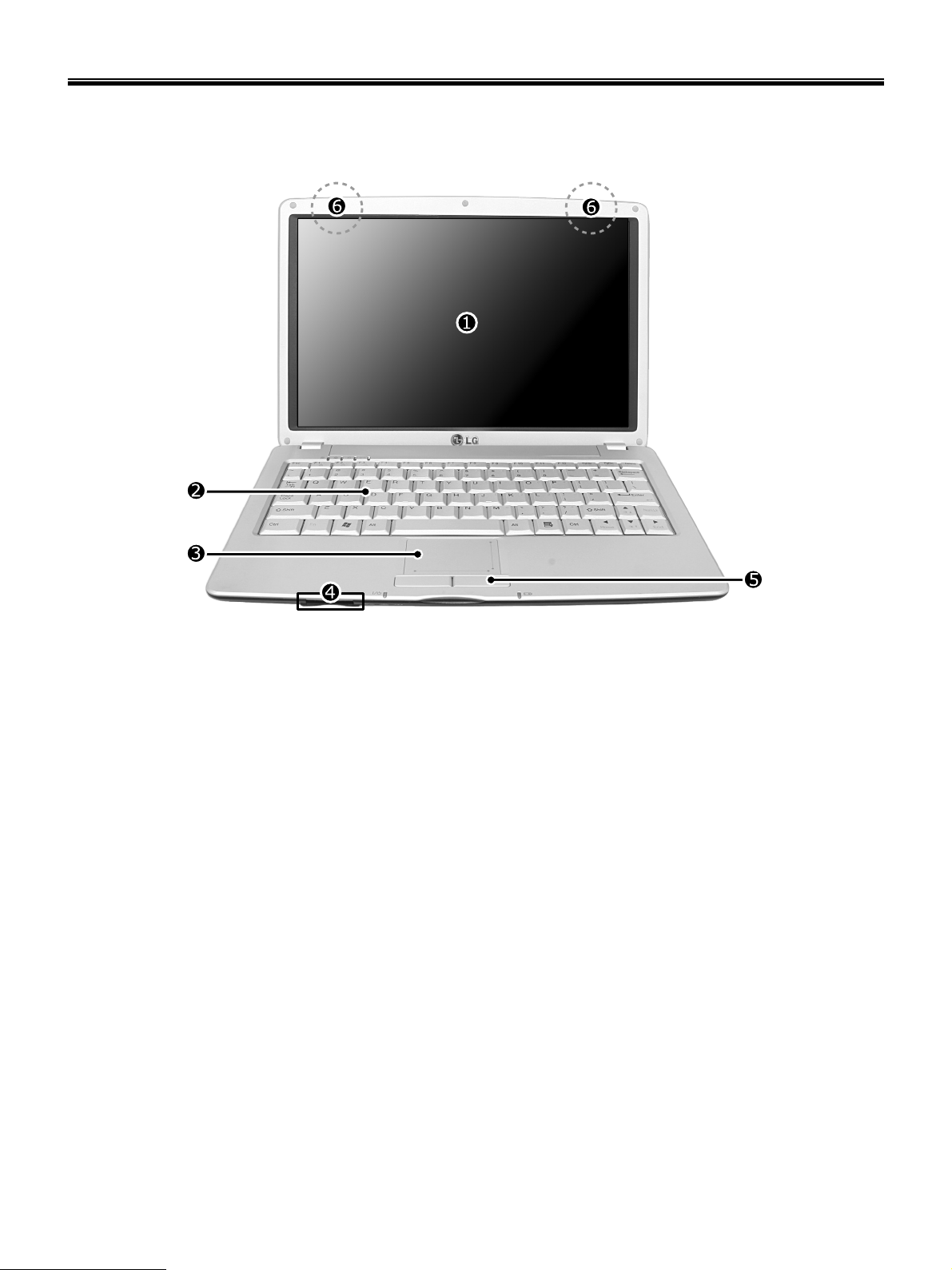
Front view (15")
Ch2. Locations
1. LCD Monitor
2. Keyboard
3. Touch pad
4. Using 5-in-1 (XD / SD / MMC / Memory Stick / Memory Stick Pro) Card
5. Touch pad button
6. Wireless LAN/Bluetooth antenna
※ The Mini-PCI Wireless Lan Card is optional.
※ Bluetooth is optional.
12
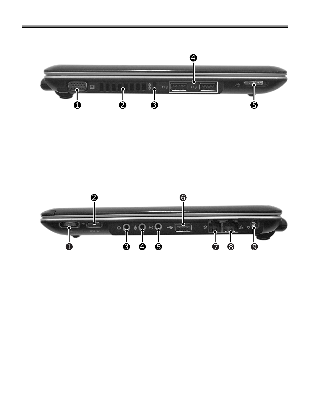
Left view
1. VGA Connector
2. Fan louvers
3. Security keyhole
4. USB Connector
5. Power button
Ch2. Locations
Right view
1. Volume up/down/mute button
2. SRS button
3. Headphone Connector / S/PDIF
4. Microphone connector
5. Line-In connector
6. USB Connector
7. Modem connector
8. LAN Connector
9. Power connector
13

Ch3. System information
Chapter 3. System information
Specification
-CPU
· Intel P-M ULV Processor 733/753 (1.1/1.2GHz) Dothan 90nm, 400MHz FSB, 2MB L2
· Intel Cel-M ULV Processor 383 (1.0GHz) Dothan 90nm, 400MHz, 1MB L2
- Main Chipset & Graphic
· Intel 915GM/PM + ICH6-M
· Intel GMA (Graphics Media Accelerators 900)
·nVIDIAG72M (VRAM: 64MB)
- Memory
· 256/512MB (DDR2 400/533MHz, Dual Ch., Up to 2GB)
-LCD
· 12.1” WXGA (1280 X 800, 16:10, FBL)
- HDD
· 40GB~80GB (1.8”, PATA, 4200rpm)
- Communication
· Qcom MA560-3 (Azalia)
· 10/100MB Ethernet
· Intel PRO/Wireless 2200BG or 2915ABG
· BMDC (Option)
-ODD
· External ODD (DVD Super-Multi)
- I/O
· 3 USB 2.0, IEEE 1394(4p), VGA, MIC-In, RJ45, RJ11(Domestic: TBD)
- Input Device
· KBD: 84keys(TBD), Touchpad w/2 buttons & scrolling Function
- Indicator
· Power/Suspend, HDD Activity, Caps Lock, Num Lock, WLAN, Battery Charge
-Button
· Power On/Off(w/LED), Volume(Jog-dial Type), SRSWOW(TBD)
- Power
· Primary: 3 Cell(3S1P, 2600mAh Cylindrical, GM: 3.38hr, PM: 2.97)
· Extended: 6 Cell(3S2P, 3800mAh Cylindrical)
· Primary + Extended: 8.26hr (GM, PM: 7.26hr)
· AC Adapter: 65W
-Weight
· 1.08kg (GM), 1.12kg (PM)
- Dimension (W X L X H)
· GM: 292 X 199 X 23.1mm
· PM: 295 X 203.5 X 23.1mm
-Others
· T-DMB Module(Built-in, Option) / WiBro Module(Built-in, Option)
14
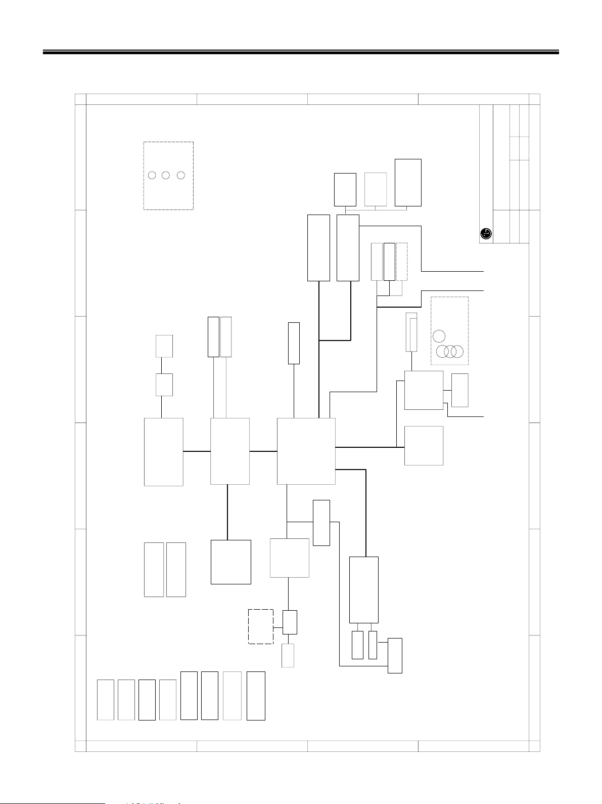
System Block Diagram
Ch3. System information
A
B
C
D
A4
of
REV 04
PC Division
6
SD/MMC
5 IN 1 CARD
page30
SUB BD
USB1
USB2/3
USB1
USB2/3
page47
MS/MSPRO/XD
USB4/5
POWER S/W
Interface BD
page42
INT. KBD
page45
VOLUME S/W
LG Electronics Inc
1394
USB4/5
SUB BOARD
LEDs
LAN
PWR
SUB BOARD
CHG
ACIN
CAPS/NUM
5
MINI PCI CONN
PIRQC/D
AD18
PCIREQ/GNT3
page20
FAN CONN
5V
page 3
LCD CONN
CRT CONN
3.3V
page21
5V
page29
PATA HDD
5V
page38
3.3V
page47
5V
3.3V
CARD BUS
page44-46
PCI7412
3.3V
PCIREQ/GNT0
PIRQA,SERIRQ
AD16
page45
PORT
1394
page30
USB0
USB0
USB Interface
4
page 3
THERMAL
SENSOR
3.3V
page 2 - 4
CPU_IO
EVEREST
CPU_CORE
(90nm/2MB L2)
(90nm/1MB L2)
Celeron M
Pentium M
FSB 400MHz
CPU_IO
TV/CRT/LVDS
915GMS
GMCH_CORE (1.05V)
page 6-11
PCI 3.3V,33MHz
PATA 66/100
DMI
page23-28
LPC 3.3V, 33MHz
ICH6-M
page41
3.3v
LPC47N350
page39
(8Mb FWH) (EC)
FLASH ROM
3.3V
page42
TOUCH PAD
PS/2
154
REV
SHEET
EVEREST MP
BLOCK DIAGRAM
2006.1.4
6871BP111AC
DATE
PART NO
TITLE
page43
63
5
4
3
2
1
page53
CPU CORE VCC
V1.2S / V1.5A
page57
CK-410M
page55
CPU_IO
GMCH_CORE
A
page22
page54
DDR2 DC/DC
page22
CK-SSCD
page52
SYSTEM DC/DC
5V/3.3V
DDR2 400MHz
page52
ACIN LOGIN
CHARGER LOGIC
page14-15
DDR2
1.8V
MICRO-DIMM
Mic IN
H/P OUT
page51
V2.5S / V2S_ATI
Miscellaneous
B
page58
page33
AZALIA
AUDIO
CODEC
AMP
5V
Int. SPK
ALC880
page32
page32
15
BMDC
DIGITAL(3.3V)
page31
ANALOGVCC(5V)
page33
5V
PCI EXPRESS
PORT 1
(10/100)
ET1301-M
Flash
page35
VPD EEPROM
C
2.5V
1.2V
Magnetic
page35
3.3V
page37
2
page36
RJ11/45 CONN
1
D

Ch3. System information
Fn key combinations
The following table shows the function of each combination of Fn with a function key.
Function of Fn keys has nothing to do with Operating System.
User defined Hot key. (Setting is available at OSD) [Fn]+[F1]
[Fn]+[F2]
[Fn]+[F3]
[Fn]+[F5]
[Fn]+[F6]
[Fn]+[F7]
User setting available in OSD. (By default, this combination is for Zoom In/Out. ※ Zoom In/Out
entails automatic adjustment of resolution.)
User setting available in OSD. (By default, this combination is for XTS Pro On/Off. ※ XTS Pro
On/Off is a new technology that realizes the optimal sound quality in playing the original sound as
it is by adjusting frequency attributes in the signal processing part that governs speaker operation
without physical alteration of speakers.)
Force the computer to enter power-saving mode. (ex: system standby or hibernation) [Fn]+[F4]
Press the combination [Fn]+[F5] keys to select or deselect Touchpad Disabled.
In Touchpad Auto-disable mode, Touchpad becomes disabled automatically if USB or PS2 mouse
is connected.
Press again to change touchpad modes.
Hotkeys to turn on/off wireless devices including wireless LAN and Bluetooth. (Bluetooth is a sales
option.)
User setting available in OSD. By default, this combination is for turning Wireless LAN and
Bluetooth on and off.
Monitor change. When the computer is attached to an external monitor, you can change the
display output location with [Fn]+[F7] combination.
[Fn]+[F11]
Power scheme change (Refer to the Battery Miser help menu). [Fn]+[F8]
Shows System information. [Fn]+[F10]
Fan control function. CPU Cooling Fan control mode (Normal / Silent (for quiet operation) / Cool
(for fast spinning)).
Maximum power-saving mode (When OSD is installed). [Fn]+[F12]
Scroll Lock [Fn]+[Esc]
Prt Sc(Sys Rq) [Fn]+[PgUp]
Pause(Break) [Fn]+[PgUp]
Insert [Fn]+[Delete]
Brighten the LCD 8-level brightness adjustment available. [Fn]+[▲]
Darken the LCD 8-level brightness adjustment available. [Fn]+[▼]
Home [Fn]+[◀]
End [Fn]+[▶]
16
Ch3. System information
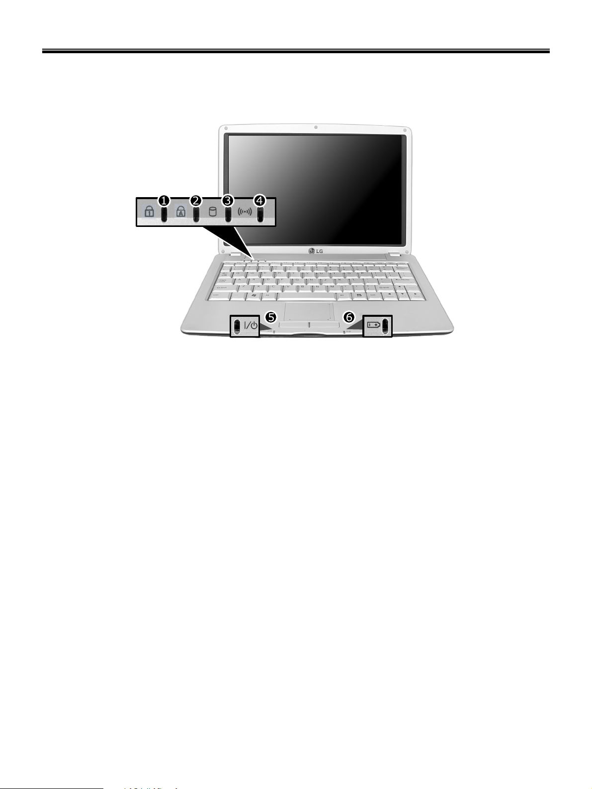
Status indicators
The system status indicators show the status of the computer
1. Num Lock Indicator
- By pressing [Fn]+[Num Lk] keys, you can enable the embedded numeric keypad. By pressing [Fn]+[Num Lk] keys
again, you can disable the embedded numeric keypad.
2. Caps Lock Indicator
- Caps Lock indicator lights up when Caps Lock key is pressed. When this indicator lights up, you can type capital
letters without pressing the Shift key.
3. Hard disk drive indicator
- Indicator lights up when the Notebook PC access to the hard disk drive.
※ Do not turn off the computer when the drive indicator lights up. It may cause data loss to the computer.
4. Wireless LAN/Bluetooth indicator
※ Wireless LAN/Bluetooth indicator operation may differ depending on the model.
※ Mini-PCI Wireless LAN Card/Bluetooth is optional.
- Indicator Off Wireless LAN/Bluetooth function not in use.
- Blinking: Wireless LAN/Bluetooth in connection with data transfer.
- Blinking(2 to 3 seconds): Wireless LAN/Bluetooth not in connection with Wireless Radio on.
- Blinking(3 to 4 seconds): Searching for access points to establish Wireless LAN/Bluetooth connection.
- ON : Searching for access points to establish Wireless LAN/Bluetooth connection, or already in connection.
5. Power indicator
- Power indicator lights up when the power cord is connected to the computer.
- OFF : Power is off, or it is entered system hibernation mode
- Green Notebook PC is turned on
- Blinking: Stand by mode
17

Ch3. System information
6. Battery status indicator: Recharging the battery (The indicator is on when recharging the battery.
- Recharging the battery : Orange
- Battery is charged over 90% : Orange, Green Indicator blinking
- Discharge : OFF
- AC Adaptor is connected with full battery or no battery : Green
- Discharging the battery or the battery is charged under 10% : Green indicator blinking
- Battery Malfunction : Red blinking
※ The Battery indicator blinks as you have set the alarm action from the Battery miser 2005.
18

Ch3. System information
BIOS Flash
You can update BIOS using a floppy disk drive.
Because this system is not equipped with any floppy disk drive, you have to use an external USB drive for
a BIOS update. In order to boot up with an USB drive, please set Removable Device as the first boot up
drive in the boot menu of BIOS setup.
· How to update flash ROM in DOS
1. Create ‘boot up’ flash update diskette.
2. Copy a ROM image file (*.wph) into the root of the flash update diskette.
3. Copy phlash16.exe to the flash update diskette.
4. Insert the diskette into the FDD of your computer.
5. Boot your computer with the diskette, and type ‘phlash16*.wph /mode=n’.
6. Cold boot and follow the instruction displayed on the screen.
· Flash options /mode=n
0 – Default mode. Keep the current DMI information and update BIOS image only.
1 – Update DMI information only.
If new DMI information is not specified, the current DMI information is left unchanged.
2 – Update BIOS and DMI information.
If new DMI information is not specified, the current DMI information is left unchanged.
3 – Update BIOS and DMI information.
DMI information is updated to the DMI string and options specified in the new BIOS image.
Note
DMI is Desktop Management Interface
19
Ch3. System information
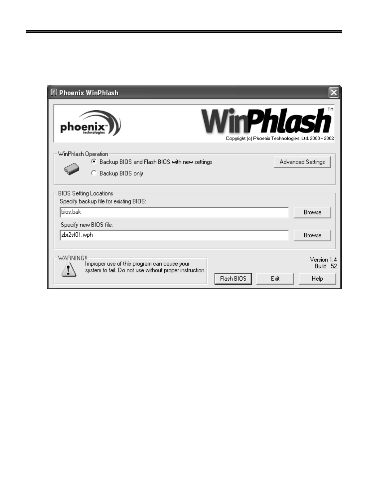
How to update flash ROM in Windows
1. Quit all running programs.
2. Start WINPHLASH.EXE.
3. Select the procedure you want :
a. Backup BIOS and Flash BIOS with new settings
b. Backup BIOS Only
4. Specify the locations for backup and new BIOS files in BIOS Setting Locations.
a. Enter the name of the backup file for existing BIOS or click Browse to locate the file.
b. Enter the name of the new BIOS file or click Browse to locate the file.
5. Click Advanced Settings button to access the advanced settings
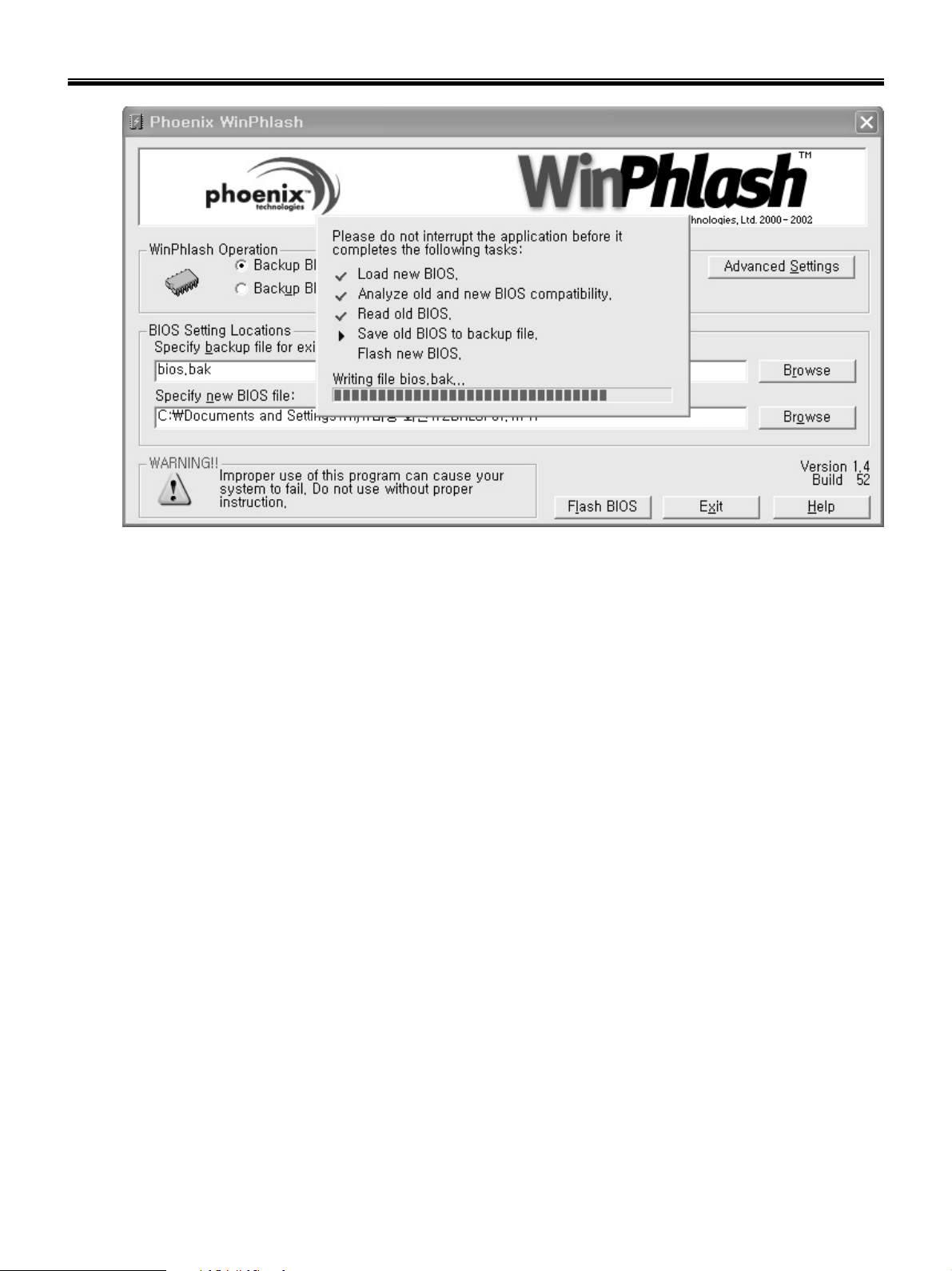
6. Click Flash BIOS button to start flash BIOS.
7. Wait for the operation to complete. WinPhlash may take one or two minutes to complete flash BIOS
operation.
20
Ch3. System information
8. After the completion, ‘System BIOS was successfully updated’ appears on the screen, then the
computer restarts.
9. After the restart, make sure the system BIOS is updated.
10. If your computer does not restart automatically, turn off your computer and then turn it back on by
pressing power button.
21
Ch3. System information
BIOS Release Process and Making Bootable CD
1. LGE(Korea) will send BIOS Image (*.iso) to each Service Centers when we have a new revision.
(Please refer to the BIOS Table (Document No. SBE-HA-01) for latest BIOS)
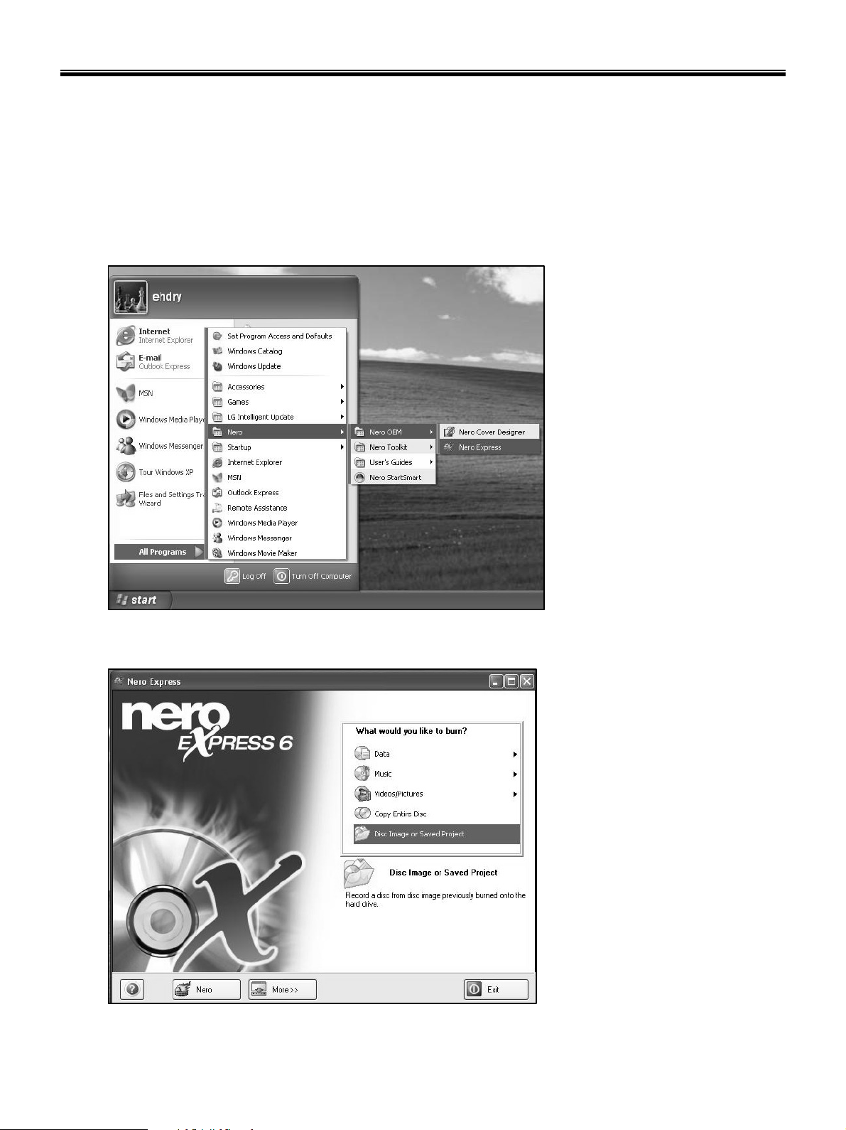
2. Service center will make Bootable Image CD with Image file(*.iso) as below
a. Insert empty disc to CD-RW Drive and start Nero Burning ROM.
b. Select Disc Image or Saved Project.
22
Ch3. System information
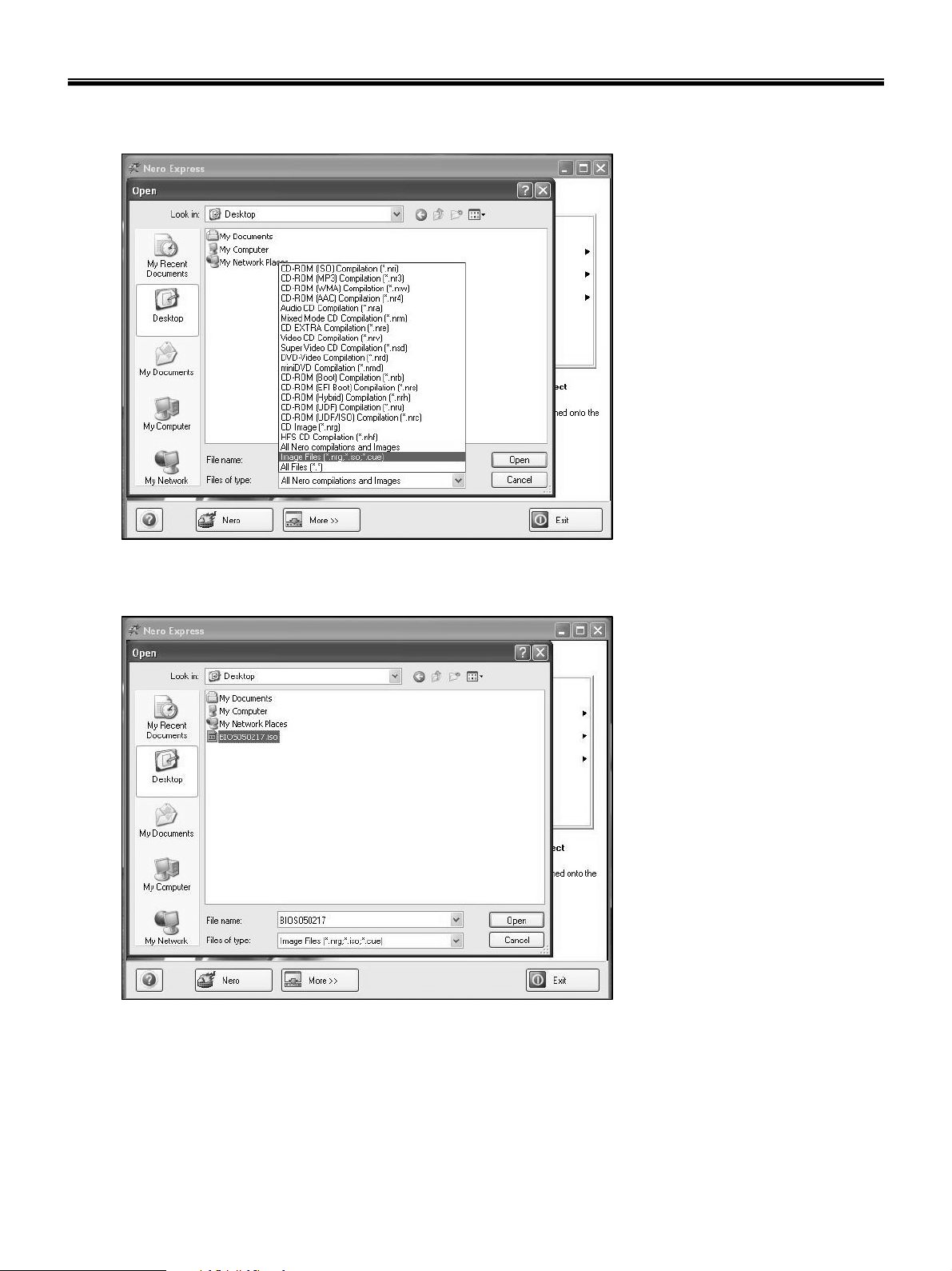
c. Select File Format as "Image Files(*.iso)".
d. Open Image File(*.iso) which is sent from LGE
23
Ch3. System information
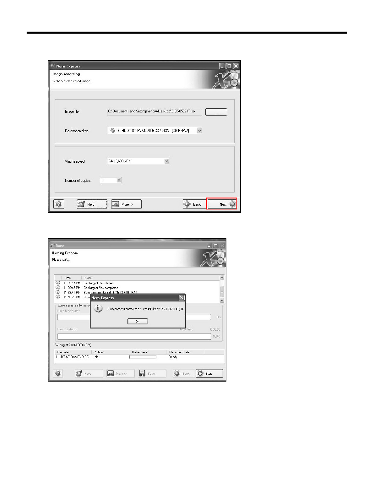
e. Tab Next then burning will be started
f. Burn process completed as below, and tab “OK”
24
Ch3. System information
BIOS/EC Flash Process
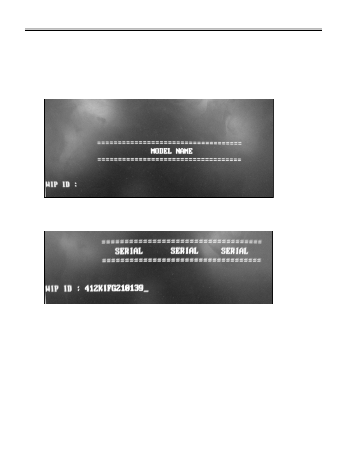
1. Insert Bootable CD in PC, and Turn it on, then PC will boot by DOS mode as below
(If the EC is not correct or old version, then automatically update EC first and reboot again)
2. Type in Mode Name at the “WIP ID :” then press Enter key (You must use Capital Letter)
(You can see the Model Name in ID Label at the bottom Case of PC: “M/N: LMXX-XXXX”)
3. Type in Serial No at the “WIP ID :” then press Enter key (You must use Capital Letter)
(You can see the Serial No in ID Label at the bottom Case of PC: “S/N: 412KIXXXXXXXX”(13digits))
25
Ch3. System information
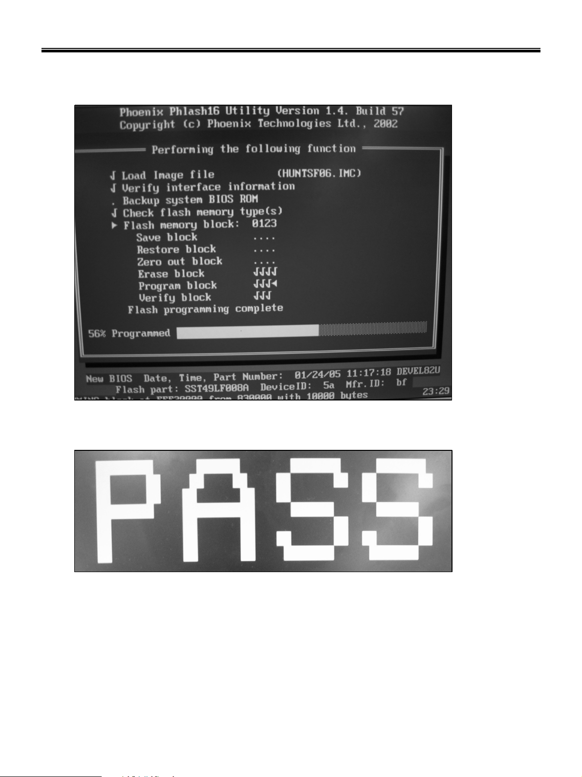
4. You can see the BIOS flash process as below
5. After flashing is completed, you can see the “PASS” on your screen, and reboot your PC
26

Ch3. System information
BIOS Setup
BIOS (Basic Input and Output System) Setup saves the system configuration in CMOS RAM, and
check the configurations during startup. Use the BIOS Setup Utility to change and save the system
environment, hardware configurations, power saving mode, etc.
· Open the BIOS Setup Utility in the following situations :
1. to change the BIOS setup
2. to replace the backup battery
3. system configuration error occurs
4. to change the boot order
5. to set/change a password
Press the power button.
When the LG logo appears on the screen, press and enter the BIOS Setup Utility.
27
Ch3. System information
Using the keys
The keys used in the BIOS Setup Utility and their functions are described at the bottom.
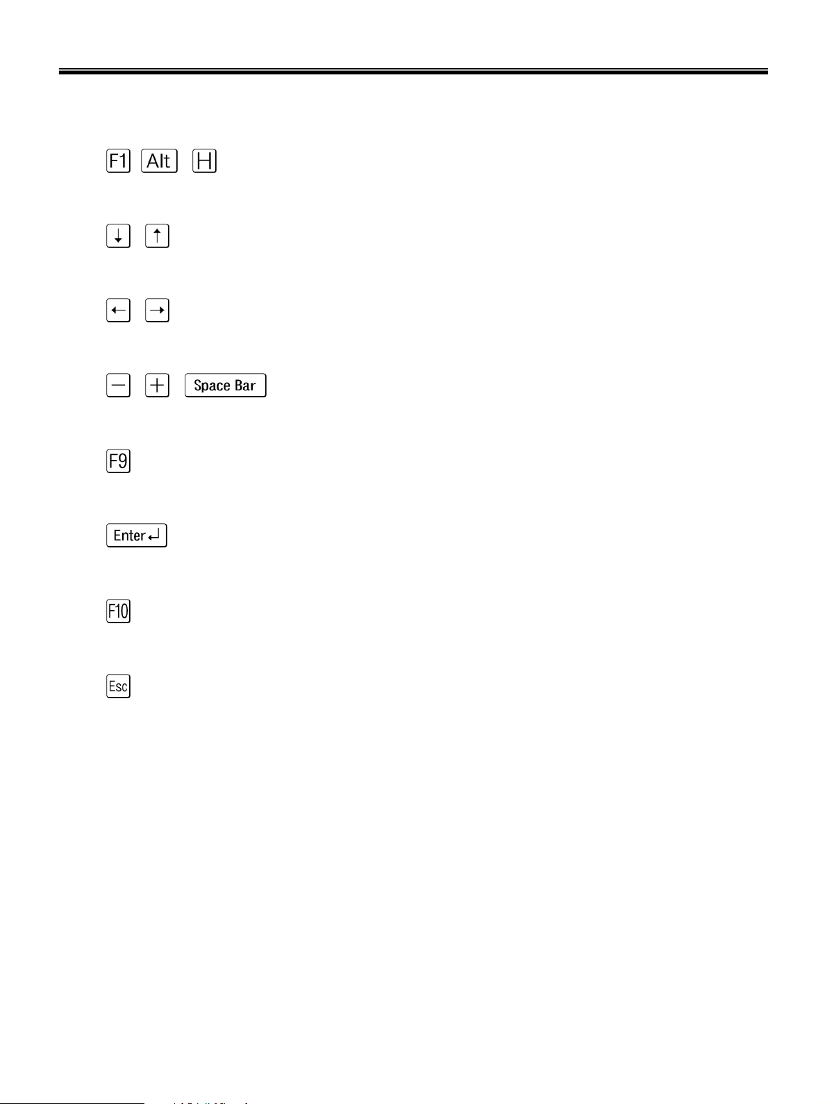
· , + : General Help
Display the descriptions of the keys used in the setup utility.
· , : Select Item
Navigate and select items in the setup utility. The selected item becomes highlighted.
· , : Select Menu
Move to another menu.
· / , : Change Values
Change the value of a selected item.
· : Load Default Configuration
Display Setup Confirmation window. Press Enter to load default configuration.
· : Select Sub-Menu
Some items have sub-menus. Display the sub-menu for a selected item.
· : Save and Exit
Display Setup Confirmation window. Press Enter to save and exit.
·: Exit
In a sub-menu, press Esc to move to the previous window. In Main menu, click Esc to move to Exit menu.
28

Ch3. System information
Main menu
System Time
Current time. Use <Tab>, <Shift-Tab>, or <Enter> keys to move around these fields. To change the
value, press <+> or <−> key.
System Date
Today date. Use <Tab>, <Shift-Tab>, or <Enter> keys to move around these fields. To change the value,
press <+> or <−> key. Set any date from year 1981 to 2079. It will automatically keep track of leap years.
The system date can also be set from the operating system.
Product Name
This shows the name of PC.
Processor Type
This shows the type of CPU.
Processor Spd
This shows the speed CPU.
BIOS Version
This shows the Version of BIOS.
KBC Version
This shows the Version of KBD firm ware.
UUID
This is for display only. This shows the UUID.
Hard Disk
Enter its submenu by pressing <Enter>. In this submenu, it would show the device of Primary IDE Master
is HDD and its parameters.
Total Memory
This is for display only. This shows size of system memory.
29
 Loading...