


SERVICE MANUAL
Room Air Conditioner
CAUTION
-BEFORE SERVICING THE UNIT, READ THE SAFETY
PRECAUTIONS IN THIS MANUAL.
-ONLY FOR AUTHORIZED SERVICE PERSONNEL.
WEBSITE http://biz.LGservice.com

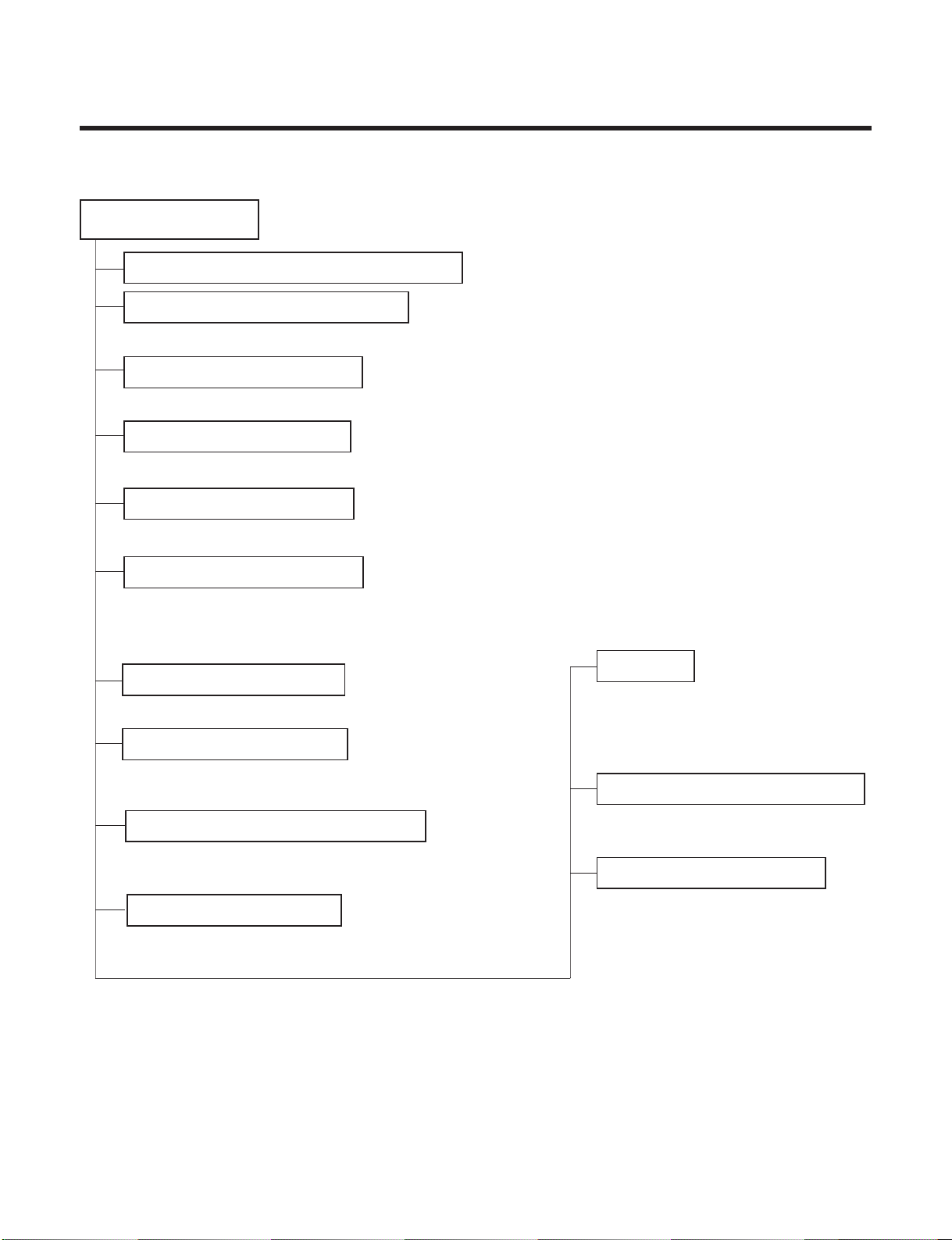
Contents
3
4
Functions ...........................................................
.....................................................................
Product References ..............................................................................................................
Dimensions............................................................................................................................. 9
Refrigeration Cyc
le Diagram............................................................................................... 11
Wiring Dia
gram..................................................................................................................... 12
Operation Details ................................................................................................................. 14
Display Function .................................................................................................................. 21
Installation ............................................................................................................................ 22
Operation .............................................................................................................................. 33
Disassembly of the pa
rts (Indoor Unit) ...........
................................................................... 34
2-way, 3-way Valve.............................................
................................................................... 36
Cycle Troubleshooting Guide...........................
................................................................... 44
Electronic Parts T
roubleshooting Guide............................................................................ 45
Electronic Control Device.................................................................................................... 52
Exploded View and Replacement Parts List...................................................................... 57
-2-
Functions
• Room temperature sensor. (THERMISTOR)
• Maintains the room temperature in accordance with the Setting Temp.
• Indoor fan is delayed for 5 sec at the starting.
• Restarting is inhibited for approx. 3 minutes.
• High, Med, Low, CHAOS
OUTDOOR---
Lights up in compressor operation (for Cooling Model)
• Intermittent operation of fan at low speed.
• The fan is switched to low(Cooling), med(Heating) speed.
• The unit will be stopped after 1, 2, 3, 4, 5, 6, 7 hours.
• The fan is switched to intermittent or irregular operation
•
The fan speed is automatically switched from high to low speed.
• The louver can be set at the desired position or swing
up and down automatically.
Indoor Unit
Operation ON/OFF by Remote controller
Sensing the Room Temperature
Room temperature control
Starting Current Control
Time Delay Safety Control
Indoor Fan Speed Control
Soft Dry Operation Mode
• The function will be operated while in any
operation mode with selecting the function.
• The function is to be stopped while it is
operating with selecting the function.
• Both the indoor and outdoor fan stops dur-
ing defrosting.
• The indoor fan stops until the
evaporator pipe temperature will be reached
at 28°C.
Sleep Mode Auto Control
Natural Air Control by CHAOS Logic
Airflow Direction Control
-3-
Defrost(Deice) control (Heating)
Hot-start Control (Heating)
PLASMA
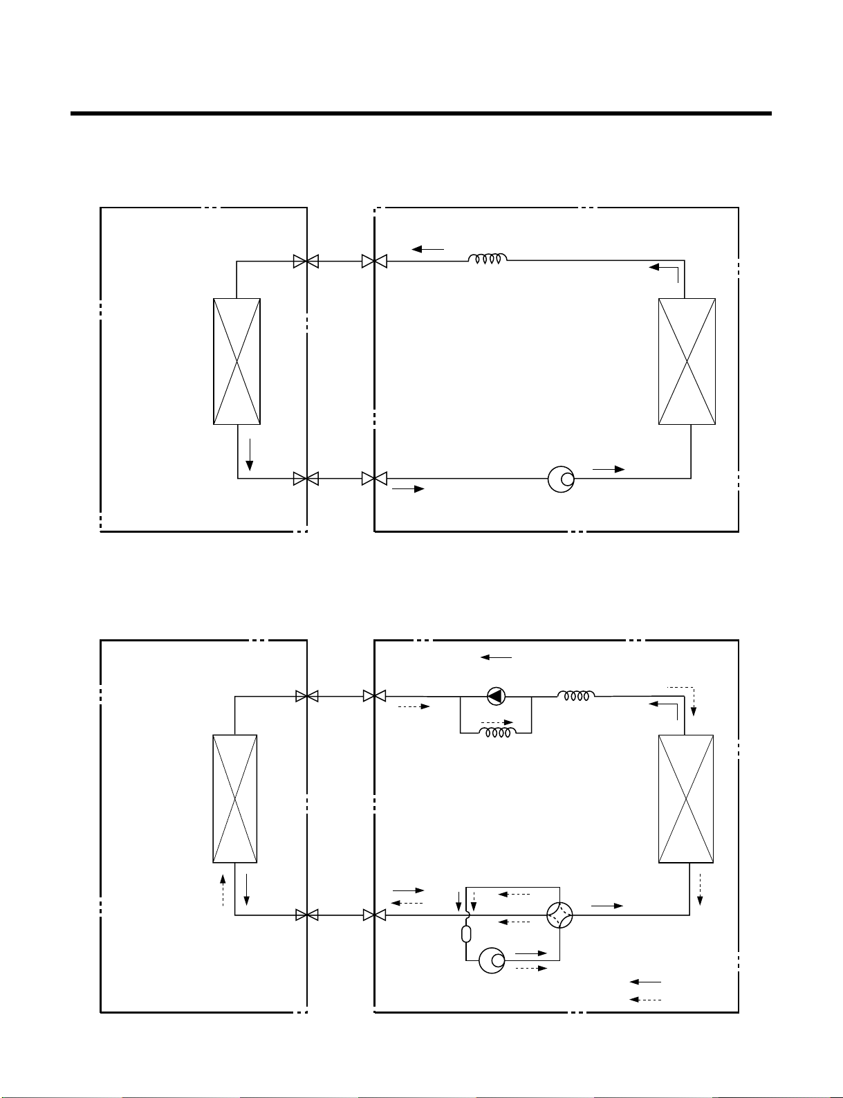
Refrigeration Cycle Diagram
-4-
INDOOR UNIT OUTDOOR UNIT
INDOOR UNIT OUTDOOR UNIT
HEAT
EXCHANGE
(EVAPORATOR)
HEAT
EXCHANGE
(EVAPORATOR)
HEAT
EXCHANGE
(CONDENSER)
HEAT
EXCHANGE
(CONDENSER)
COMPRESSOR
COMPRESSOR
ACCUMU
LATOR
GAS SIDE
GAS SIDE
VALVE
LIQUID SIDE
LIQUID SIDE
VALVE
CAPILLARY TUBE
CAPILLARY TUBE
CHECK VALVE
(Heating Model only)
COOLING
HEATING
REVERSING
VALVE
(Heating Model Only)
(1) Cooling Only Models
(2) Cooling & Heating Models

Operation Details
1. MAIN UNIT FUNCTION
• DISPLAY
1) C/O Model
Operation Indicator
• ON while in appliance operation, OFF while in appliance pause.
• Flashing while in disconnection or short in Thermistor. (3 sec off / 0.5 sec on)
Sleep Timer Indicator
• ON while in sleep timer mode, OFF when sleep timer cancel or appliance operation pause.
Timer Indicator
• ON while in timer mode (on/off), OFF when timer mode is completed or canceled.
Comp. Running Incidator
• While in appliance operation, ON while in outdoor unit compressor running, OFF while in compressor off.
2) H/P Model
Operation Indicator
• ON while in appliance operation, OFF while in appliance pause.
• Flashing while in disconnection or short in Thermistor. (3 sec off / 0.5 sec on)
Sleep Timer Indicator
• ON while in sleep timer mode, OFF when sleep timer cancel or appliance operation pause.
Timer Indicator
• ON while in timer mode (on/off), OFF when timer mode is completed or canceled.
Defrost Indicator
• OFF except when hot start during heating mode operation or while in defrost control.
■ Cooling Mode Operation
• When the intake air temperature reaches 0.5°C below the setting temp, the compressor and the outdoor fan
stop.
• When it reaches 0.5°C above the setting temp, they start to operate again.
Compressor ON Temp ➲ Setting Temp+0.5°C
Compressor OFF Temp ➲ Setting Temp-0.5°C
• While in compressor running, operating with the airflow speed set by the remote control. While in compressor
not running, operating with the low airflow speed regardless of the setting.
■ Healthy Dehumidification Mode
• When the dehumidification operation input by the remote control is received, the intake air temperature is
detected and the setting temp is automatically set according to the intake air temperature.
26°C ≤ Intake Air Temp ➲ 25°C
24°C ≤ Intake Intake Air Temp<26°C ➲ Intake Air Temp-1°C
18°C ≤ Intake Intake Air Temp<24°C ➲ Intake Air Temp-0.5°C
Intake Air Temp<18°C ➲ 18°C
-5-

• While in compressor off, the indoor fan repeats low airflow speed and pause.
• While the intake air temp is between compressor on temp. and compressor off temp., 10-min dehumidifica-
tion operation and 4-min compressor off repeat.
Compressor ON Temp. ➲ Setting Temp+0.5°C
Compressor OFF Temp. ➲ Setting Temp-0.5°C
• In 10-min dehumidification operation, the indoor fan operates with the low airflow speed.
■ Heating Mode Operation
• When the intake air temp reaches +3°…above the setting temp, the compressor is turned off. When below
the setting temp, the compressor is turned on.
Compressor ON Temp. ➲ Setting Temp.
Compressor OFF Temp. ➲ Setting Temp.+3°C
• While in compressor on, the indoor fan is off when the indoor pipe temp. is below 20°C, when above 28°C , it
operates with the low or setting airflow speed. When the indoor pipe temp is between 20°C and 28°C, it operates with Super-Low(while in sleep mode, with the medium airflow speed).
• While in compressor off, the indoor fan is off when the indoor pipe temp is below 33°C, when above 35°C , it
operates with the low airflow speed.
• If overloaded while in heating mode operation, in order to prevent the compressor from OLP operation, the
outdoor fan is turned on/off according to the indoor pipe temp.
• While in defrost control, both of the indoor and outdoor fans are turned off.
■ Defrost Control
• While in heating mode operation in order to protect the evaporator pipe of the outdoor unit from freezing,
reversed to cooling cycle to defrost the evaporator pipe of the outdoor unit.
• After 40 min heating mode operation, at 4 min interval, whether to carry out defrost control or not and the time
of defrost control are determined according to the following conditions.
1) While in heating mode operation, the maximum of the indoor pipe temperature is measured and it is com-
pared with the present indoor pipe temperature to get the difference of the indoor pipe temperatures (=the
maximum temperature of indoor pipe ? the present temperature of indoor pipe), according to which, whether
to carry out defrost control or not is determined.
2) According to the need of defrost control shown above and the elapsed time of heating mode operation at that
moment, the defrost control time is determined.
3) When the determined time of defrost control is below 7 min, heating mode operation continues without carry-
ing out defrost control. According to the procedure stated above, the determination is made again. When the
defrost control time is 7 min or longer, defrost control is then carried out.
• While in defrost control, the minimum temp of the indoor pipe is measured and it is compared with the present
temp of the indoor pipe to get the difference of the indoor pipe temperatures (=the present temperature of the
indoor pipe ? the minimum temperature of the indoor pipe). When the difference is 5°C or higher, defrost control is completed and heating mode operation is carried out.
• While in defrost control, if the defrost time determined before the start of defrost control is completed, defrost
control stops and heating mode operation is carried out regardless of the above condition.
• When the indoor pipe temp is 42°C or above, defrost control is not carried out even if the condition is one of
the defrost conditions above.
• While in defrost control, the compressor is on and the indoor fan, the outdoor fan, and the 4 way valve are off.
-6-

-7-
■ Fuzzy Operation (C/O Model)
• According to the temperature set by Fuzzy rule, when the intake air temp is 0.5°C or more below the setting
temp, the compressor is turned off. When 0.5°C or more above the setting temp, the compressor is turned on.
Compressor ON Temp ➲ Setting Temp + 0.5°C
Compressor OFF Temp ➲ Setting Temp + 0.5°C
• At the beginning of Fuzzy mode operation, the setting temperature is automatically selected according to the
intake air temp at that time.
26°C ≤ Intake Air Temp ➲ 25°C
24°C ≤ Intake Air Temp < 26°C ➲ Intake Air Temp + 1°C
22°C ≤ Intake Air Temp < 24°C ➲ Intake Air Temp + 0.5°C
18°C ≤ Intake Air Temp < 22°C ➲ Intake Air Temp
Intake Air Temp<18°C ➲ 18°C
• When the Fuzzy key (Temperature Control key) is input after the initial setting temperature is selected, the
Fuzzy key value and the intake air temperature at that time are compared to select the setting temperature
automatically according to the Fuzzy rule.
• While in Fuzzy operation, the airflow speed of the indoor fan is automatically selected according to the
temperature.
■ Fuzzy Operation (H/P Model)
• When any of operation mode is not selected like the moment of the power on or when 3 hrs has passed since
the operation off, the operation mode is selected.
• When determining the operation mode, the compressor, the outdoor fan, and the 4 way valve are off and only
the indoor fan is operated for 15 seconds. Then an operation mode is selected according to the intake air
temp at that moment as follows.
24°C ≤ Inatake Air Temp ➲ Fuzzy Operation for Cooling
21°C ≤ Inatake Air Temp<24°C ➲ Fuzzy Operation for Dehumidification
Inatake Air Temp<21°C ➲ Fuzzy Operation for Heating
• If any of the operation modes among cooling / dehumidification / heating mode operations is carried out for 10
sec or longer before Fuzzy operation, the mode before Fuzzy operation is operated.
1) Fuzzy Operation for Cooling
• According to the setting temperature selected by Fuzzy rule, when the intake air temp is 0.5°C or more below
the setting temp, the compressor is turned off. When 0.5°C or more above the setting temp, the compressor
is turned on.
Compressor ON Temp ➲ Setting Temp +0.5°C
Compressor OFF Temp ➲ Setting Temp + 0.5°C
• At the beginning of Fuzzy mode operation, the setting temperature is automatically selected according to the
intake air temp at that time.
26°C≤ Intake Air Temp ➲ 25°C
24°C≤ Intake Air Temp<26°C ➲ Intake Air Temp + 1°C
22°C≤ Intake Air Temp<24°C ➲ Intake Air Temp + 0.5°C
18°C≤ Intake Air Temp<22°C ➲ Intake Air Temp
Intake Air Temp<18°C ➲ 18°C
• When the Fuzzy key (Temperature Control key) is input after the initial setting temperature is selected, the
Fuzzy key value and the intake air temperature at that time are compared to select the setting temperature
automatically according to the Fuzzy rule.
• While in Fuzzy operation, the airflow speed of the indoor fan is automatically selected according to the temperature.

-8-
2) Fuzzy Operation for Dehumidification
• According to the setting temperature selected by Fuzzy rule, when the intake air temp is 0.5°C or more below
the setting temp, the compressor is turned off. When 0.5°C or more above the setting temp, the compressor
is turned on.
Compressor ON Temp ➲ Setting Temp + 0.5°C
Compressor OFF Temp ➲ Setting Temp+0.5°C
• At the beginning of Fuzzy mode operation, the setting temperature is automatically selected according to the
intake air temp at that time.
26°C ≤ Intake Air Temp ➲ 25°C
24°C ≤ Intake Air Temp<26°C ➲ Intake Air Temp+1°C
22°C ≤ Intake Air Temp<24°C ➲ Intake Air Temp+0.5°C
18°C ≤ Intake Air Temp<22°C ➲ Intake Air Temp
Intake Air Temp<18°C ➲ 18°C
• When the Fuzzy key (Temperature Control key) is input after the initial setting temperature is selected, the
Fuzzy key value and the intake air temperature at that time are compared to select the setting temperature
automatically according to the Fuzzy rule.
• While in Fuzzy operation, the airflow speed of the indoor fan repeats the low airflow speed or pause as in
dehumidification operation.
3) Fuzzy Operation for Heating
• According to the setting temperature selected by Fuzzy rule, when the intake air temp is 3°C or more above
the setting temp, the compressor is turned off. When below the setting temp, the compressor is turned on.
Compressor ON Temp ➲ Setting Temp
Compressor OFF Temp ➲ Setting Temp + 3°C
• At the beginning of Fuzzy mode operation, the setting temperature is automatically selected according to the
intake air temp at that time.
20°C≤Intake Air Temp ➲ Intake Air Temp + 0.5°C
Intake Air Temp<20°C ➲ 20°C
• When the Fuzzy key (Temperature Control key) is input after the initial setting temperature is selected, the
Fuzzy key value and the intake air temperature at that time are compared to select the setting temperature
automatically according to the Fuzzy rule.
• While in Fuzzy operation, the airflow speed of the indoor fan is set to the high or the medium according to the
intake air temperature and the setting temperature.
■ Airflow Speed Selection
• The airflow speed of the indoor fan is set to high, medium, low, or chaos (auto) by the input of the airflow
speed selection key on the remote control.
■ On-Timer Operation
• When the set time is reached after the time is input by the remote control, the appliance starts to operate.
• The timer LED is on when the on-timer is input. It is off when the time set by the timer is reached.
• If the appliance is operating at the time set by the timer, the operation continues.

-9-
■ Off-Timer Operation
• When the set time is reached after the time is input by the remote control, the appliance stops operating.
• The timer LED is on when the off-timer is input. It is off when the time set by the timer is reached.
• If the appliance is on pause at the time set by the timer, the pause continues.
■ Off-Timer ↔ On-Timer Operation
• When the set time is reached after the on/off time is input by the remote control, the on/off-timer operation is
carried out according to the set time.
■ Sleep Timer Operation
• When the sleep time is reached after <1,2,3,4,5,6,7,0(cancel) hr> is input by the remote control while in appli-
ance operation, the operation of the appliance stops.
• While the appliance is on pause, the sleep timer mode cannot be input.
• While in cooling mode operation, 30 min later since the start of the sleep timer, the setting temperature
increases by 1°C. After another 30 min elapse, it increases by 1°C again.
• When the sleep timer mode is input while in cooling cycle mode, the airflow speed of the indoor fan is set to the
low.
• When the sleep timer mode is input while in heating cycle mode, the airflow speed of the indoor fan is set to
the medium.
■ Chaos Swing Mode
• By the Chaos Swing key input, the upper/lower vane automatically operates with the Chaos Swing or they are
fixed to the desired direction.
• While in Chaos Swing mode, the angles of cooling and heating cycle operations are different.
■ Chaos Natural Wind Mode
• When the Chaos Natural Wind mode is selected and then operated, the high, medium, or low speed of the air-
flow mode is operated for 2~15 sec. randomly by the Chaos Simulation.
CLOSED
OPEN
< Cooling Mode >
7°
CLOSED
OPEN
< Heating Mode >
7°
-10-
■ Forced Operation
• Operation procedures when the remote control can't be used.
• The operation will be started if the power button is pressed.
• If you want to stop operation, re-press the button.
• While in forced operation, the key input by the remote control has no effect and the buzzer sounds 10 times to
indicate the forced operation.
■ Test operation
•
During the TEST OPERATION, the unit operates in cooling mode at high speed fan, regardless of room temperature and resets in 18±1 minutes.
•
During test operation, if remote controller signal is received, the unit operates as remote controller sets.
If you want to use this operation, open the front panel upward and Press the power button let it be pressed for
about 3 seconds.
•
If you want to stop the operation, re-press the button.
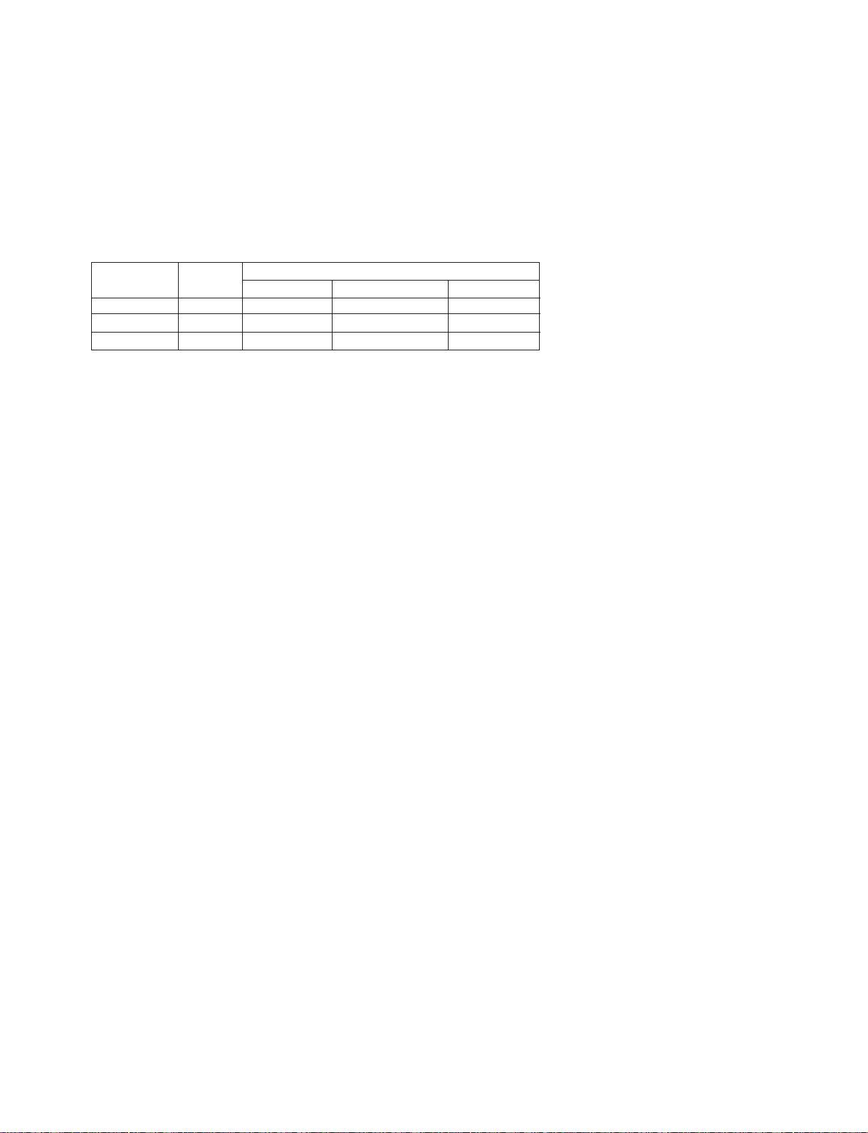
■ Auto restart
•
In case the power comes on again after a power failure, Auto Restarting Operation is the function to operate
procedures automatically to the previous operating conditions.
Heat pump Model
Cooling Model
Room Temp. ≥ 24°C 21°C ≤ Room
Temp. < 24°C Room Temp. < 21°C
Operating mode Cooling Cooling Healthy Dehumidification Heating
Indoor FAN Speed
High High High High
Setting Temperature
22°C 22°C 23°C 24°C

-11-
■ Remote Control Operation Mode
• When the remote control is selected by the slide switch on the main unit, the appliance operates according to
the input by the remote control.
■ Protection of the evaporator pipe from frosting
• If the indoor pipe temp is below 0°C in 7 min. after the compressor operates without any pause while in cooling cycle operation mode, the compressor and the outdoor fan are turned off in order to protect the indoor
evaporator pipe from frosting.
• When the indoor pipe temp is 7°C or higher after 3 min. pause of the compressor, the compressor and the
outdoor fan is turned on according to the condition of the room temperature.
■ Buzzer Sounding Operation
• When the appliance-operation key is input by the remote control, the short "beep-beep-" sounds.
• When the appliance-pause key is input by the remote control, the long "beep—" sounds.
• When a key is input by the remote control while the slide switch on the main unit of the appliance is on the
forced operation position, the error sound "beep-beep-beep-beep-beep-" is made 10 times to indicate that the
remote control signal cannot be received.
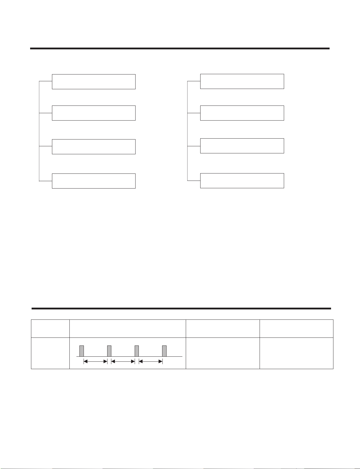
Display Function
-12-
Self-diagnosis Function
3sec 3sec 3sec
(once)
Error
Code
1
Error Display LED
(Indoor body operation LED)
Error contents
• Indoor room temperature
thermistor open/short
• Indoor pipe temperature
thermistor open/short.
• Indoor Thermistor
assembly check
SVC check point
1. Heating Model 2. Cooling Model
• Cooling, Soft Dry, Fan, Heating • Cooling, Soft Dry, Fan
• Sleep Mode • Sleep Mode
• Timer Mode • Timer Mode
• Hot-start, Defrost
Operation Indicator
Timer Indicator
Sleep Timer Indicator
Defrost Indicator
Operation Indicator
Timer Indicator
Sleep Timer Indicator
Compressor Indicator
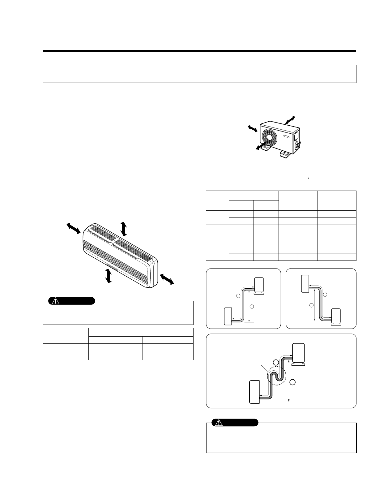
1) Selection of the best location
1. Indoor unit
• Do not have any heat or steam near the unit.
• Select a place where there are no obstacles in front of
the unit.
• Make sure that condensation drainage can be conveniently routed away.
Do not install near a doorway.
• Ensure that the space around the left and right of the
unit is more than "A". The unit should be installed as
high on the wall as possible, allowing a minimum of
"B" from ceiling.
• Use a stud finder to locate studs to prevent unnecessary damage to the wall.
2. Outdoor unit
• If an awning is built over the unit to prevent direct sunlight or rain exposure, make sure that heat radiation
from the condenser is not restricted.
• Ensure that the space around the back and sides is
more than 10cm. The front of the unit should have
more than 70cm of space.
• Do not place animals and plants in the path of the
warm air.
• Take the air conditioner weight into account and select
a place where noise and vibration are minimum.
• Select a place so that the warm air and noise from the
air conditioner do not disturb neighbors.
2) Piping length and elevation
Installation
1. Installation of indoor, Outdoor unit
-13-
More than "A"
More than "B"
More than 2.3m
More than "B"
More than 10 cm
More than 10 cm
More than 70 cm
Install the indoor unit on the wall where the height
from the floors more than 2.3 meters.
CAUTION
• Capacity is based on standard length and maximum
allowance length is on the basis of reliability.
• Oil trap should be installed every 5~7 meters.
CAUTION
Grade
Clearance(cm)
A B
7K~28K 10 5
30K~38K 30 12
Pipe Size
Capacity
(Btu/h)
GAS LIQUID
Max.
Length
A (m)
Additional
Refrigerant
(g/m)
Max.
Elevation
B (m)
Standard
Length
(m)
7k~14k
3/8"(Ø9.52) 1/4"(Ø6.35) 4 or 7.5 7 15 20
1/2"(Ø
12.7) 1/4"(Ø6.35) 4 or 7.5 7 15 20
1/2"(Ø
12.7) 1/4"(Ø6.35) 4 or 7.5 15 30 20
18k~28
k 5/8"(Ø15.88) 1/4"(Ø6.35) 4 or 7.5 15 30 20
5/8"(Ø
15.88) 3/8"(Ø9.52) 4 or 7.5 15 30 30
30k~38
k
5/8"(Ø15.88) 3/8"(Ø9.52) 7.5 15 30 30
3/4"(Ø
19.05) 3/8"(Ø9.52) 7.5 15 30 50
If case more than 5m
Outdoor unit
Indoor unit
A
B
Outdoor unit
Indoor unit
A
B
A
Oil trap
Outdoor unit
Indoor unit
B
I

-14-
3) Drill a hole in the wall
• Drill the piping hole with a ø70mm hole core drill. Drill
the piping hole at either the right or the left with the
hole slightly slanted to the outdoor side.
mm7-5
)"61/5~"61/3(
Indoor
WALL
Outdoor

-15-
2. Flaring Work and Connection of Piping
1) Flaring work
Main cause for refrigerant leakage is due to defect in
the flaring work. Carry out correct flaring work using the
following procedure.
1. Cut the pipes and the cable.
•
Use the piping kit accessory or pipes purchased locally.
• Measure the distance between the indoor and the
outdoor unit.
• Cut the pipes a little longer than the measured
distance.
• Cut the cable 1.5m longer than the pipe length.
2. Burr removal
• Completely remove all burrs from the cut cross section of pipe/tube.
• Put the end of the copper tube/pipe in a downward
direction as you remove burrs in order to avoid dropping burrs into the tubing.
3. Putting nut on
• Remove flare nuts attached to indoor and outdoor
unit, then put them on pipe/tube having completed
burr removal.
(not possible to put them on after flaring work)
4. Flaring work
• Firmly hold copper pipe in a die in the dimension
shown in the table above.
• Carry out flaring work using flaring tool as shown
below.
5. Check
• Compare the flared work with figure below.
• If flare is noted to be defective, cut off the flared sec-
tion and re-flare it.
Copper
pipe
90°
Slanted Uneven Rough
Bar
Copper pipe
Clamp handle
Red arrow mark
Cone
Yoke
Handle
Bar
"A"
Inclined
Inside is shiny without scratches
Smooth all round
Even length
all round
Surface
damaged
Cracked Uneven
thickness
= Improper flaring =
Pipe
Reamer
Point down
Flare nut
Copper tube
mm inch mm
Ø6.35 1/4 0~0.5
Ø9.52 3/8 0~0.5
Ø12.7 1/2 0~0.5
Ø15.88 5/8 0~1.0
Ø19.05 3/4 1.0~1.3
Outside diameter

-16-
2) Connection of piping Indoor
• Preparing the indoor unit's piping and drain hose for
installation through the wall.
• Remove the plastic tubing retainer(see illustration
below) and pull the tubing and drain hose away from
chassis.
• Replace the plastic tubing holder in the original position.
1. Route the indoor tubing and the drain hose in the
direction of rear right.
2. Insert the connecting cable into the indoor unit
from the outdoor unit through the piping hole.
• Do not connect the cable to the indoor unit.
• Make a small loop with the cable for easy
connection later.
3. Tape the tubing, drain hose, and the connecting
cable. Be sure that the drain hose is located at the
lowest side of the bundle. Locating at the upper
side can cause drain pan to overflow inside the
unit.
NOTE: If the drain hose is routed inside the room,
insulate the hose with an insulation material* so that
dripping from "sweating"(condensation) will not damage
furniture or floors.
*Foamed polyethylene or equivalent is recommended.
4. Indoor unit installation
• Hook the indoor unit onto the upper portion of the
installation plate.(Engage the two hooks of the rear
top of the indoor unit with the upper edge of the installation plate.) Ensure that the hooks are properly seated on the installation plate by moving it left and right.
Press the lower left and right sides of the unit against
the installation plate until the hooks engage into their
slots(clicking sound).
4. Connecting the pipings to the indoor unit and drain
hose to drain pipe.
• Align the center of the pipes and sufficiently tighten
the flare nut by hand.
For right rear piping
CAUTION
When install, make sure
that the remaining parts
must be removed clearly
so as not to damage the
piping and drain hose,
especially power cord
and connecting cable.
Loop
Tubing holder
Connecting
cable
Drain hose
Gas side
piping
Liquid side
piping
Connecting
cable
Drain hose
Drain hose
Indoor unit tubing Flare nut Pipes

-17-
• Tighten the flare nut with a wrench.
• When extending the drain hose at the indoor unit,
install the drain pipe.
5. Wrap the insulation material around the connecting
portion.
• Overlap the connection pipe insulation material and
the indoor unit pipe insulation material. Bind them
together with vinyl tape so that there is no gap.
• Wrap the area which accommodates the rear piping
housing section with vinyl tape.
• Bundle the piping and drain hose together by wrapping them with vinyl tape for enough to cover where
they fit into the rear piping housing section.
1. Route the indoor tubing and the drain hose to the
required piping hole position.
2. Insert the piping, drain hose, and the connecting
cable into the piping hole.
For left rear piping
mm inch kg.m
Ø6.35 1/4 1.8
Ø9.52 3/8 4.2
Ø12.7 1/2 5.5
Ø15.88 5/8 6.6
Ø19.05 3/4 6.6
Outside diameter Torque
Wrench
Indoor unit tubing
Open-end wrench (fixed)
Connection pipe
Flare nut
Vinyl tape(narrow)
Adhesive
Drain pipe
Indoor unit drain hose
Plastic bands
Insulation material
Vinyl tape(narrow)
Connection
pipe
Connecting cable
Vinyl tape
(wide)
Wrap with vinyl tape
Indoor
unit pipe
Pipe
Wrap with vinyl tape
Drain hose
Pipe
Vinyl tape(wide)
Drain pipe
Connecting cable

-18-
3. Insert the connecting cable into the indoor unit.
• Don't connect the cable to the indoor unit.
• Make a small loop with the cable for easy connection
later.
4. Tape the drain hose and the connecting cable.
• Connecting cable
5. Indoor unit installation
• Hang the indoor unit from the hooks at the top of the
installation plate.
• Insert the spacer etc. between the indoor unit and the
installation plate and separate the bottom of the
indoor unit from the wall.
6. Connecting the pipings to the indoor unit and the
drain hose to drain pipe.
• Align the center of the pipes and sufficiently tighten
the flare nut by hand.
• Tighten the flare nut with a wrench.
• When extending the drain hose at the indoor unit,
install the drain pipe.
7. Wrap the insulation material around the connecting portion.
• Overlap the connection pipe heat insulation and the
indoor unit pipe heat insulation material. Bind them
together with vinyl tape so that there is no gap.
• Wrap the area which accommodates the rear piping
housing section with vinyl tape.
mm inch kg.m
Ø6.35 1/4 1.8
Ø9.52 3/8 4.2
Ø12.7 1/2 5.5
Ø15.88 5/8 6.6
Ø19.05 3/4 6.6
Outside diameter Torque
Vinyl tape
Adhesive
Drain hose
Indoor unit drain hose
(narrow)
Plastic bands
Insulation material
Vinyl tape(narrow)
Connection
pipe
Connecting cable
Indoor
unit piping
Pipe
Vinyl tape
(wide)
Wrap with vinyl tape
Installation plate
Spacer
Indoor unit
8cm
Indoor unit tubing Flare nut Pipes
Wrench
Connection pipe
Flare nut
Open-end wrench (fixed)

-19-
• Bundle the piping and drain hose together by wrapping them with cloth tape over the range within which
they fit into the rear piping housing section.
8. Reroute the pipings and the drain hose across the
back of the chassis.
9. Set the pipings and the drain hose to the back of
the chassis with the tubing holder.
• Hook the edge of tubing holder to tap on chassis and
push the bottom of tubing holder to be engaged at the
bottom of chassis.
10. Indoor unit installation
• Remove the spacer.
• Ensure that the hooks are properly seated on the
installation plate by moving it left and right.
Press
the lower left and right sides of the unit against
the installation plate until the hooks engage into their
slots(clicking sound).
3) Connection of the pipes-Outdoor
1. Align the center of the pipings and sufficiently
tighten the flare nut by hand.
2. Finally, tighten the flare nut with torque wrench
until the wrench clicks.
• When tightening the flare nut with torque wrench,
ensure the direction for tightening follows the arrow on
the wrench.
mm inch kg.m
Ø6.35 1/4 1.8
Ø9.52 3/8 4.2
Ø12.7 1/2 5.5
Ø15.88 5/8 6.6
Ø19.05 3/4 6.6
Outside diameter Torque
Drain hose
Vinyl tape(narrow)
Pipe
Wrap with
vinyl tape(wide)
Piping for
passage through
piping hole
Outdoor unit
Gas side piping
(Bigger diameter)
Liquid side
piping
(Smaller
diameter)
Torque wrench
Tubing holder
Drain hose
Connecting
cable

-20-
3. Connecting The Cable Between Indoor Unit and Outdoor Unit
1) Connect the cable to the Indoor unit.
• Connect the cable to the indoor unit by connecting the wires to the terminals on the control board in
dividually according to the outdoor unit connection. (Ensure that the color of the wires of the outdoor unit and
the terminal No. are the same as those of the indoor unit.)
The earth wire should be longer than the common wires.
Air
Conditioner
Main power source
If a power plug is not to be used, provide a circuit breaker
between power source and the unit as shown below.
Circuit Breaker
Use a circuit
breaker or time
delay fuse.
CAUTION
CAUTION
The power cord connected to the "A" unit should be
complied with the following specifications
(Type "B" approved by HAR or SAA).
Grade
5k~9K 12k~14k 18k 24k~28k 30k, 32k 36k, 38k
0.75 1.0 1.5 2.5 2.5 5.5
Unit(A) Indoor Indoor Indoor Indoor Outdoor Outdoor
Cable Type(B)
H05VV-F H05VV-F H05VV-F H05VV-F H05RN-F H05RN-F
NORMAL
CROSS
-SECTIONAL
AREA
5k~9k 12k~14k 18k 24k~28k
0.75 1.0 1.5 2.5
Cable Type(B) H07RN-F H07RN-F H07RN-F H07RN-F
NORMAL
CROSS
-SECTIONAL
AREA
Grade
30k, 32k 36k, 38k
0.75 0.75
Cable Type(B) H07RN-F H07RN-F
NORMAL CROSS
-SECTIONAL AREA
Grade
(mm2)
(mm
2
)
(mm
2
)
The power connecting cable connected to the indoor
and outdoor unit should be complied with the following
specifications
(Type "B" approved by HAR or SAA).
NORMAL
CROSS-SECTIONAL
AREA 0.75mm
2
• The above circuit diagram is subject to change without notice.
• Be sure to connect wires according to the wiring diagram.
• Connect the wires firmly, so that not to be pulled out
easily.
• Connect the wires according to color codes by referring the wiring diagram.
CAUTION
• When installing, refer to the circuit diagram on the
Control Box of Indoor Unit.
• When installing, refer to the wiring diagram on the
Control Cover Inside Outdoor Unit.

-21-
2) Connect the cable to the outdoor unit
1. Remove the control cover from the unit by loos-
ening the screw.
Connect the wires to the terminals on the control
board individually.
2. Secure the cable onto the control board with the
cord clamp.
3. Refix the control cover to the original position
with the screw.
4. Use a recognized circuit breaker "A"
between the power source and the unit.
A disconnecting device to adequately disconnect
all supply lines must be fitted.
Outdoor unit
Over 5mm
Terminal block
(Pillar terminal)
Holder for
power supply
cord
Cover control
Connecting cable
LS-Q096ABL
After the confirmation of the above conditions, prepare the wiring as follows:
1) Never fail to have an individual power circuit specifically for the air conditioner. As for the method of
wiring, be guided by the circuit diagram posted on the inside of control cover.
2) The screw which fasten the wiring in the casing of electrical fittings are liable to come loose from
vibrations to which the unit is subjected during the course of transportation. Check them and make
sure that they are all tightly fastened. (If they are loose, it could cause burn-out of the wires.)
3) Specification of power source.
4) Confirm that electrical capacity is sufficient.
5) See to that the starting voltage is maintained at more than 90 percent of the rated voltage marked on
the name plate.
6) Confirm that the cable thickness is as specified in the power source specification.
(Particularly note the relation between cable length and thickness. (Refer to page 28))
7) Always install an earth leakage circuit breaker in a wet or moist area.
8) The following would be caused by voltage drop.
• Vibration of a magnetic switch, which will damage the contact point, fuse breaking, disturbance of the normal
function of the overload.
9) The means for disconnection from a power supply shall be incorporated in the fixed wiring and have an
air gap contact separation of at least 3mm in each active(phase) conductors.
CAUTION
7k~14k 18k 24k~28k 30k, 32k 36k, 38k
15 20 30 30 40
Circuit
Breaker
(A)
Grade

-22-
4. Checking the Drainage and Forming the Pipings
1) Checking the drainage
1. To remove the front panel from the indoor unit.
• Set the air direction louvers up-and-down to the position(horizontally) by hand.
• Remove the securing screws that retain the front panel. Pull the lower left and right sides of the grille
toward you and lift it off.
2. To check the drainage.
• Pour a glass of water on the evaporator.
• Ensure the water flows through the drain hose of the
indoor unit without any leakage and goes out the drain
exit.
3. Drain piping
• The drain hose should point downward for easy drain
flow.
• Do not make drain piping.
2) Form the piping
1. Form the piping by wrapping the connecting portion of the indoor unit with insulation material and
secure it with two kinds of vinyl tapes.
• If you want to connect an additional drain hose, the
end of the drain outlet should be routed above the
ground. Secure the drain hose appropriately.
2. In cases where the outdoor unit is installed below
the indoor unit perform the following.
• Tape the piping, drain hose and connecting cable from
down to up.
• Secure the tapped piping along the exterior wall using
saddle or equivalent.
3. In cases where the Outdoor unit is installed above
the Indoor unit perform the following.
•
Tape the piping and connecting cable from down to up.
• Secure the taped piping along the exterior wall. Form
a trap to prevent water entering the room.
• Fix the piping onto the wall by saddle or equivalent.
Pull the right and
the left side.
Taping
Drain
hose
Pipings
Connecting
cable
Trap is required to prevent water
from entering into electrical parts.
Seal small openings
around pipings with a
gum type sealer.
Taping
Drain hose
Pipings
Connecting
cable
LS-Q096AAL LS-Q096ABL
Seal a small opening
around the pipings
with gum type sealer.
Trap
Trap
Downward slope
Do not raise
Accumulated
drain water
Tip of drain hose
dipped in water
Air
Waving
Water
leakage
Water
leakage
Ditch
Less than
50mm gap
Water
leakage

-23-
1. Check that all tubing and wiring have been properly
connected.
2. Check that the gas and liquid side service valves are
fully open.
1. Prepare remote control
1. Remove the battery cover
by pulling it according to the
arrow direction.
2. Insert new batteries making
sure that the (+) and (–) of
battery are installed correctly.
3. Reattach the cover by
pushing it back into position.
NOTE:
• Use 2 AAA(1.5volt) batteries. Do not use recharge-
able batteries.
• Remove the batteries from the remote control if the
system is not going to be used for a long time.
2. Settlement of outdoor unit
• Anchor the outdoor unit with a bolt and nut(ø10mm)
tightly and horizontally on a concrete or rigid mount.
• When installing on the wall, roof or rooftop, anchor the
mounting base securely with a nail or wire assuming
the influence of wind and earthquake.
• In the case when the vibration of the unit is conveyed
to the hose, secure the unit with an anti-vibration
bushing.
3. Evaluation of the performance
Operate unit for 15~20 minutes, then check the system
refrigerant charge:
1. Measure the pressure of the gas side service valve.
2. Measure the temperature of the intake and discharge
of air.
3. Ensure the difference between the intake temperature and the discharge is more than 8°C(46°F) (Cooling) or (Heating).
4. For reference; the gas side pressure of optimum condition is as below.(Cooling)
NOTE: If the actual pressure is higher than shown, the
system is most likely over-charged, and charge
should be removed. If the actual pressure are
lower than shown, the system is most likely
undercharged, and charge should be added.
The air conditioner is now ready for use.
Bolt
Tubing connection
Discharge
temperature
Discharge air
Intake temperature
5. Test Running
R-22 35°C (95°F) 4~5kg/cm2G(56.8~71.0 P.S.I.G.)
Outside ambient
TEMP.
Refrigerant
The pressure of the gas side
service valve.
This is performed when the unit is to be relocated
or the refrigerant circuit is serviced.
Pump Down means collecting all refrigerant in the
outdoor unit without loss in refrigerant gas.
CAUTION:
Be sure to perform Pump Down procedure with the
unit cooling mode.
Pump Down Procedure
1. Connect a low-pressure gauge manifold hose to
the charge port on the gas side service valve.
2. Open the gas side service valve halfway and purge
the air from the manifold hose using the refrigerant
gas.
3. Close the liquid side service valve(all the way in).
4. Turn on the unit's operating switch and start the
cooling operation.
5. When the low-pressure gauge reading becomes 1
to 0.5kg/cm2 G(14.2 to 7.1 P.S.I.G.), fully close the
gas side valve stem and then quickly turn off the
unit. At that time, Pump Down has been completed
and all refrigerant gas will have been collected in
the outdoor unit.
PUMP DOWN

-24-
Disassembly of the parts (Indoor unit)
Warning :
Disconnect the unit from power supply before making
any checks.
Be sure the power switch is set to “OFF”.
To remove the Grille from the Chassis.
• Set the up-and-down air discharge louver to open
position (horizontally) by finger pressure.
• Remove the securing screws.
• To remove the Grille, pull the lower left and right
side of the grille toward you (slightly tilted) and lift it
straight upward.
1. Before removing the control box, be sure to
take out the wire screwed at the other end.
Display
P.C.B
Conductor
Step Motor
Conductor
Earth
Conductor
Motor
Conductor
Sensor
Conductor

-25-
2. To remove the Control Box.
• Remove securing screws.
• Pull the control box out from the chassis careful-
ly.
3. To remove the Discharge Grille.
• Unhook the discharge grille and pull the discharge grille out from the chassis carefully.
4. To remove the Evaporator.
• Remove 3 screws securing the evaporator(at the
left 2EA in the Eva Holder, at the right 1EA).
Caution label
When repair, do not damage the Caution
label.

-26-
• Unhook the tab on the right inside of the chassis
at the same time, slightly pull the evaporator
toward you until the tab is clear of the slot.
5. To remove the Motor Cover
• Remove 2 securing screw.
• Pull the motor cover out from the chassis
carefully.
6. To remove the Cross-Flow Fan
• Loosen the screw securing the cross-flow fan to
the fan motor (do not remove).
• Lift up the right side of the cross-flow fan and the
fan motor, separate the fan motor from the
cross-flow fan.
• Remove the left end of the cross-flow fan from
the self-aligning bearing.
Motor cover

2-way, 3-way Valve
2-way Valve (Liquid Side) 3-way Valve (Gas Side)
Shaft position Shaft position Service port
Closed Closed Closed
(with valve cap) (with valve cap) (with cap)
Open Closed Open
(counter-clockwise) (clockwise) (push-pin or with
vacumm pump)
Open Open Closed
(with valve cap) (with valve cap) (with cap)
Closed Open Open
(clockwise) (counter-clockwise) (connected manifold
gauge)
Open Open Open
(with charging
cylinder)
Open Open Open
(with charging
cylinder)
Open Open
Open Open
Works
Shipping
Air purging
(Installation)
Operation
Pumping down
(Transfering)
Evacuation
(Servicing)
Gas charging
(Servicing)
Pressure check
(Servicing)
Gas releasing
(Servicing)
1.
2.
3.
4.
5.
6.
Valve cap
Open position
Closed position
Pin
Service
port
Service
port cap
To outdoor unit
Flare nut
To
piping
connection
To outdoor unit
Hexagonal wrench (4mm)
Open position
Closed position
To
piping
connection
Flare nut
-27-
Open
(with charging cylinder)
Open
(with charging cylinder)

1. Air purging
Required tools : hexagonal wrench, adjustable
wrench, torque wrenches, wrench to
hold the joints, and gas leak detector.
The additional gas for air purging has been charged
in the outdoor unit.
However, if the flare connections have not be done
correctly and there gas leaks, a gas cylinder and the
charge set will be needed.
The air in the indoor unit and in the piping must be
purged. If air remains in the refrigeration pipes, it will
affect the compressor, reduce to cooling capacity, and
could lead to a malfunction.
• Procedure
(1) Recheck the piping connections.
(2) Open the valve stem of the 2-way valve coun-
terclockwise approximately 90°, wait 10 seconds, and then set it to closed position.
– Be sure to use a hexagonal wrench to operate
the valve stem.
(3) Check for gas leakage.
– Check the flare connections for gas leakage.
(4) Purge the air from the system.
– Set the 2-way valve to the open position and
remove the cap from the 3-way valve’s service
port.
– Using the hexagonal wrench to press the valve
core pin, discharge for three seconds and then
wait for one minute. Repeat this three times.
(5) Use torque wrench to tighten the service port
nut to a torque of 1.8kg.cm.
(6) Set the 3-way valve to the back seat.
(7) Mount the valve stem nuts to the 2-way and 3-
way valves.
(8) Check for gas leakage.
– At this time, especially check for gas leakage
from the 2-way and 3-way valve’s stem nuts,
and from the service port nut.
Caution
If gas leakage are discovered in step (3) above,
take the following mesures :
If the gas leaks stop when the piping connections
are tightened further, continue working from step (4).
If the gas leaks do not stop when the connections
are retightened, repair the location of the leak, discharge all of the gas through the service por t, and
then recharge with the specified amount of gas
from a gas cylinder.
Service port nut:
Be sure, using a torque wrench to tighten the service port nut (after using the service port), so that it prevents the
gas leakage from the refrigeration cycle.
* CAUTION : Do not leak the gas in the air during Air purging.
Liquid side
Outdoor unit
3-way
valve
Gas side
Indoor unit
2-way
valve
Open
Clsed
-28-

2. Pumping down
• Procedure
(1) Confirm that both the 2-way and 3-way valves
are set to the open position.
– Remove the valve stem caps and confirm that
the valve stems are in the raised position.
– Be sure to use a hexagonal wrench to operate
the valve stems.
(2) Operate the unit for 10 to 15 minutes.
(3) Stop operation and wait for 3 minutes, then
connect the charge set to the service port of
the 3-way valve.
– Connect the charge hose with the push pin to
the service port.
(4) Air purging of the charge hose.
– Open the low-pressure valve on the charge set
slightly to air purge from the charge hose.
(5) Set the 2-way valve to the closed position.
(6) Operate the air conditioner at the cooling
cycle and stop it when the gauge indicates
1kg/cm2g.
(7) Immediately set the 3-way valve to the closed
position.
– Do this quickly so that the gauge ends up indi-
cating 3 to 5kg/cm2g.
(8) Disconnect the charge set, and mount the 2-
way and 3-way valve’s stem nuts and the ser-
vice port nut.
– Use torque wrench to tighten the service por t
nut to a torque of 1.8 kg.m.
– Be sure to check for gas leakage.
Lo
Closed
Purge the air
Outdoor unit
Indoor unit
Liquid side
Gas side
CLOSE
Open
2-Way
valve
3-Way
valve
CLOSE
-29-

1) Re-air purging
(Re-installation)
• Procedure
(1) Confirm that both the 2-way valve and the 3-
way valve are set to the closed position.
(2) Connect the charge set and a gas cylinder to
the service port of the 3-way valve.
– Leave the valve on the gas cylinder closed.
(3) Air purging.
– Open the valves on the gas cylinder and the
charge set. Purge the air by loosening the flare
nut on the 2-way valve approximately 45° for 3
seconds then closing it for 1 minute; repeat 3
times.
– After purging the air, use a torque wrench to
tighten the flare nut on the 2-way valve.
(4) Check for gas leakage.
– Check the flare connections for gas leakage.
(5) Discharge the refrigerant.
– Close the valve on the gas cylinder and dis-
charge the refrigerant until the gauge indicates
3 to 5 kg/cm2g.
(6) Disconnect the charge set and the gas cylin-
der, and set the 2-way and 3-way valves to the
open position.
– Be sure to use a hexagonal wrench to operate
the valve stems.
(7) Mount the valve stem nuts and the service
port nut.
– Use torque wrench to tighten the service por t
nut to a torque of 1.8 kg.m.
– Be sure to check for gas leakage.
* CAUTION:
Do not leak the gas in the air during Air Purging.
Lo
Closed
OPEN
Closed
Gas cylinder
R22
Outdoor unit
Indoor unit
Liquid side
Gas side
CLOSE
2-Way
valve
3-Way
valve
-30-

2) Balance refrigerant of the 2-way, 3-way valves
(Gas leakage)
• Procedure
(1) Confirm that both the 2-way and 3-way valves
are set to the back seat.
(2) Connect the charge set to the 3-way valve’s
port.
– Leave the valve on the charge set closed.
– Connect the charge hose with the push pin to
the service port.
(3) Open the valve (Lo side) on the charge set
and discharge the refrigerant until the gauge
indicates 0 kg/cm2G.
– If there is no air in the refrigerant cycle (the
pressure when the air conditioner is not running is higher than 1 kg/cm2G), discharge the
refrigerant until the gauge indicates 0.5 to 1
kg/cm2G. if this is the case, it will not be necessary to apply a evacuatin.
– Discharge the refrigerant gradually; if it is dis-
charged too suddenly, the refrigeration oil will
also be discharged.
Lo
Open
Open
3-Way
valve
2-Way
valve
Gas side
CLOSEOPEN
Outdoor unit
Liquid side
Indoor unit
-31-

3. Evacuation
(All amount of refrigerant leaked)
• Procedure
(1) Connect the vacuum pump to the charge set’s
center hose
(2) Evacuation for approximately one hour.
– Confirm that the gauge needle has moved
toward -76 cmHg (vacuum of 4 mmHg or less).
(3) Close the valve (Lo side) on the charge set,
turn off the vacuum pump, and confirm that
the gauge needle does not move (approximately 5 minutes after turning off the vacuum
pump).
(4) Disconnect the charge hose from the vacuum
pump.
– Vacuum pump oil.
If the vacuum pump oil becomes dirty or
depleted, replenish as needed.
Lo
Open
Open
Vacuum pump
2-Way
valve
Outdoor unit
Liquid side
Indoor unit
Gas side
3-Way
valve
CLOSE
OPEN
-32-

Cycle Troubleshooting Guide
Trouble analysis
1. Check temperature difference between intake and discharge air and operating current.
Temp. Difference
Temp. difference : approx. 0°C
Current : less than 80% of
rated current
Temp. difference : approx. 8°C
Current : less than 80% of
rated current
Temp. difference : less than 8°C
Current : over the reated
current
Temp. difference : over 8°C
Operating Current
• All amount of refrigerant leaked
out. Check refrigeration cycle.
• Refrigerant leakege
Clog of refrigeration cycle
Defective compressor
• Excessive amount of refrigerant
• Normal
Notice :
Temperature difference between intake and discharge air depends on room air humidity. When the room air
humidity is relativery higher, temperature difference is smaller. When the room air humidity is relatively lower temperature difference is larger.
2. Check temperature and pressure of refrigeration cycle.
Notice :
1. The suction pressure is usually 4.5~6.0 kg/cm2G(Cooling) at normal condition.
2. The temperature can be measured by attaching the thermometer to the low pressure tubing and wrap it with
putty.
Suction pressure Temperature
(Compared with (Compared with Cause of Trouble Description
the normal value) the normal valve)
Defective compressor Current is low.
Defective 4-way reverse valve
Excessive amount of High pressure does not quickly
Normal refrigerant rise at the beginning of
operation.
Insufficient amount of Current is low.
Lower Higher refrigerant (Leakage)
Clogging Current is low.
High
Higher
-34-

4. Gas Charging
(After Evacuation)
• Procedure
(1) Connect the charge hose to the charging
cylinder.
– Connect the charge hose which you dis-con-
nected from the vacuum pump to the valve at
the bottom of the cylinder.
– If you are using a gas cylinder, also use a scale
and revers the cylinder so that the system can
be charged with liquid.
(2) Purge the air from the charge hose.
– Open the valve at the bottom of the cylinder
and press the check valve on the charge set to
purge the air. (Be careful of the liquid refrigerant). The procedure is the same if using a gas
cylinder.
(3) Open the valve (Lo side on the charge set and
charge the system with liquid refrigerant.
– If the system can not be charged with the spec-
ified amount of refrigerant, it can be charged
with a little at a time (approximately 150g each
time) while operating the air conditioner in the
cooling cycle; however, one time is not sufficient, wait approximately 1 minute and then
repeat the procedure (pumping down-pin).
(4) Immediately disconnect the charge hose from
the 3-way valve’s service port.
– Stopping partway will allow the gas to be dis-
charged.
– If the system has been charged with liquid
refrigerant while operating the air conditioner
turn off the air conditioner before disconnecting
the hose.
(5) Mount the valve stem nuts and the service
port nut.
– Use torque wrench to tighten the service por t
nut to a torque of 1.8 kg.m.
– Be sure to check for gas leakage.
\
This is different from previous procedures.
Because you are charging with liquid refrigerant
from the gas side, absolutely do not attempt to
charge with larger amounts of liquid refrigerant
while operating the air conditioner.
-33-
Indoor unit
Liquid side
Gas side
Check valve
Charging
cylinder
Lo
(1)
OPEN
CLOSE
Open
Outdoor unit
2-Way
valve
Open
3-Way
valve

-35-
Electronic Parts Troubleshooting Guide
1. Product does not operate at all.
(* Refer to Electronic Control Device drawing and Schematic diagram.)
Turn off Main Power
Turn on Main Power
Does "beeping" sound is made from the Indoor Unit?
Primarily, the operating condition of Micom is OK.
Check the voltage of po wer(About A C 220V, 60Hz)
(About AC 220/240V, 50Hz)
• Main power's voltage
• Voltage applied to the unit
• Connecting method of Indoor/Outdoor connecting
cable
• Check PWB Assembly
- Fuse
- Pattern damage
- Varistor(ZNR01J)
Check the connection housing for contacting
• Connector related to CN-TAB1, RY-COMP NO.3
• Connector related to CN-MOTOR
• Connector contacting of Outdoor Fan/Compressor
• Display PWB Assembly Check
Check each load(Indoor/Outdoor Fan Motor, Compressor, Stepping Motor) and contacting
condition of related connector
Main PCB Board Operation Check
Items
• SMPS Transformer
(Indoor unit)
- Input Voltage
- Output Voltage(ZD02D)
• IC04D(7805) Output
(Indoor/Outdoor unit)
• IC01A(KIA7036, Reset IC)
X01(8MHz)
• Replace Trans
• Replace IC04D
• Replace faulty parts
- About AC220V/240V±10% - Check the power voltage
- About DC12V
• DC +5V
• Voltage of Micom No. 2,
(DC +4.5V over) and Soldering condition.
Content Remedy
NO
YES
(After 10 seconds)

-36-
2. The product is not operate with the remote control.
Turn on Main Power
While the compressor has been stopped, the compressor does not
operate owing to the delaying function for 3 minutes after stopped.
Caused by other parts except the remote control
Cause by the remote control
When the mark( ) is displayed in LCD screen, replace
battery .
Check the contact of CN-DISP1 connector.
When the compressor stopped Indoor Fan is driven by a low speed.
At this point the wind speed is not controlled by the remote controller.
(When operated in the Sleeping Mode, the wind speed is set to the
low speed by force.)
Check Display PWB Assembly
- Voltage between CN DISP1 - : DC +5V
Check the connecting circuit between the remote controller
MICOM (No. ) - R17(2Ω) - IR LED - TR - R16(2.2KΩ).
Check point
• Check the connecting circuit between CN-DISP1
-
R01L(5.1K) - C01L(680pF) - MICOM PIN
• Check Receiver Assembly
43
2

-37-
3. Compressor/Outdoor Fan are unable to drive.
Turn on Main Power
Operate "Cooling Mode( )" by setting the desired temperature of the
remote controller is less than one of the indoor temperature by 1°C at least.
When in Air Circulation Mode, Compressor/Outdoor Fan is stopped.
Check the sensor for indoor temperature is attached as close as to be
effected by the temperature of Heat Exchanger(EVA).
When the sensor circuit for indoor temperature and connector are in bad
connection or are not engaged, Compressor/Outdoor Fan is stopped.
• Check the related circuit of RY-FAN.
• Check the indoor temper ature sensor is disconnected or not(About 10k Ω/ at 25°C).
Turn off Main Power
• Check the electrical wiring diagram of outdoor side.
• Check the abnormal condition for the component of Compressor/Out-
door Fan Motor.
• Check the "open" or "short" of conmecting wires between indoor and
outdoor.
Check Relay(RY - COMP) for driving compressor.
• When the power(About AC220V/240V) is applied to the connecting wire
terminal support transferred to compressor, PWB Assembly is normal.
• Check the circuit related to the relay.
Check point COMP ON COMP OFF
Between Micom(No.
DC5V DC0V
62) and GND
Between IC01M(No. 14) Below DC 1V
About DC12V
and GND (app)

-38-
Check the TRIAC high speed operation by remote control.
(The Indoor Fan Motor is connected)
Turn off Main power
Check the connection of CN-MOTOR
Check the Fan Motor
Check the Fuse(AC250V/T2A)
Turn ON Main Power
Check the related circuit of indoor Fan Motor.
• The pin NO 58 of Micom, and the part for driving TRIAC(the input and
output signal of IC01M, PIN NO 7, 10)
• Check the pattern
• Check the TRIAC
- TRIAC Open: Indoor Fan Motor never operate
- TRIAC short: Indoor Fan Motor always operates in case of ON or OFF.
4. When indoor Fan does not operate.
The voltage of PIN NO 1(orange) and 3(yellow) of CN-MOTOR.
About AC 180V over About AC 50V over
TRIAC is not damaged TRIAC Check

-39-
• Confirm that the Vertical Louver is normally geared with the shaft of
Stepping Motor.
• If the regular torque is detected when rotating the Vertical Louver with
hands Normal
• Check the connecting condition of CN-U/D Connector
• Check the soldering condition(on PWB) of CN-U/D Connector
If there are no problems after above checks
• Confirm the assembly conditions that are catching and interfering parts
in the rotation radial of the Vertical Louver
5. When Vertical Louver does not operate.
Check the operating circuit of the Vertical Louver
• Confirm that there is DC +12V between pin (RED) of CN-U/D and
GND.
• Confirm that there is a soldering short at following terminals.
- Between , , and of MICOM
- Between , , and of IC01M
- Between , , and of IC01M
60 61 62 63

-40-
6. When Heating does not operate
Operate “Heating Mode( )” by setting the desired temperature of the
remote control is higher than one of the indoor temperature by 2°C at
least.
In heating Mode, the indoor fan operates in case the pipe temperature
is higher than 28°C.
Check the connector of intake and pipe sensor(thermistors)
• Check the related circuit of RY-4WAY
• Check the indoor room temperature is disconnected or not (about
10KΩ/at 25°C).
• Check the indoor pipe temperature is disconnected or not (about
5KΩ/at 25°C).
Turn ON Main Power
Check the DC voltage on the PWB ASSEMBLY
• The details of check are as followings
Check point
Between Micom
(NO.59) and GND
Between IC01M
(NO.11) and GND
Comp ON
DC 5V
Below DC 1V
Comp OFF
DC 0V
About DC
12V
Check point
Between Micom
(NO.51) and GND
Between IC02M
(NO.11) and GND
4 way ON
DC 5V
Below DC 1V
4 way OFF
DC 0V
About DC 12V
Check point
Between Micom
(NO.53) and GND
Between IC02M
(NO.12) and GND
Fan ON
DC 5V
Below DC 1V
Fan OFF
DC 0V
About DC 12V
• Comp Relay.
• 4 way Relay
• Outdoor fan Relay

-41-
Turn off Main Power
• Check the electrical wiring diagram of outdoor side.
• Check the abnormal condition for the component of Compressor/Out-
door Fan Motor, 4 way.
• Check the "open" or "short" of connecting wires between indoor and
outdoor.

435511
437212
559010
W0CZZ
W6640
649950
552203-2
552203-1
447910
554031
550140
148000
237202
435301
349600
552116
546810
552202
561410
430400
552111
430410
554160
W6631

 Loading...