

LG TCH-M1000, TCH-M1001 User Manual

STEREO CD CAR RECEIVER
OWNER’S MANUAL
MODEL : TCH-M1000 / TCH-M1001
To fully enjoy the features and functions of this new unit,
we recommend that you read this OWNER’S MANUAL
carefully and completely.
Internet address ; http://ua.lge.com
Customer Information Center LG ; (380-44) 490-7777, 8-800-303-0000
Precautions
2
Explanation Graphical Symbols:
The lightning flash with arrowhead symbol, within an
equilateral triangle is intended to alert the user to the
presence of uninsulated dangerous voltage within the
product’s enclosure that may be of sufficient magnitude
to constitute a risk of electric shock to persons.
The exclamation point within an equilateral triangle is
intended to alert the user to the presence of important
operating and maintenance(servicing) instructions in
the literature accompanying the appliance.
WARNING
TO REDUCE THE RISK OF FIRE OF ELECTRIC SHOCK, DO
NOT EXPOSE THIS APPLIANCE TO RAIN OR MOISTURE.
To avoid electrical shock, do not open the cabinet, Refer
servicing to qualified personnel only.
RISK OF ELECTRIC
SHOCK DO NOT OPEN
CAUTION
CAUTION:TO REDUCE THE RISK OF ELECTRIC SHOCK
DO NOT REMOVE COVER(OR BACK) NO USER
SERVICEABLE PARTS INSIDE. REFER SERVICING TO
QUALIFIED SERVICE PERSONNEL.
CAUTION
Use of controls or adjustments or performance of procedures
other than those specified here in may result in hazardous
radiation exposure.
Laser component in this product is capable of emitting
radiation exceeding the limit for Class 1.
CLASS 1 LASER PRODUCT
KLASSE 1 LASER PRODUKT
LUOKAN 1 LASER LAITE
KLASS 1 LASER APPARAT
CLASSE 1 PRODUIT LASER
This Compact Disc player is classified as a CLASS 1 LASER product.
The CLASS 1 LASER PRODUCT label is located on the exterior.
The apparatus shall not be exposed to dripping or splashing
and that no objects filled with liquids, such as vases, shall
be placed on the apparatus.
Warning:
Do not install this equipment in a confined space such a book
case or similar unit.
CAUTION:INVISIBLE LASER RADIATION WHEN OPEN AND
INTERLOCKS DEFEATED. AVOID EXPOSURE TO BEAM.
VARNING:OSYNLIG LASERSTRÅLNING NÄR DENNA DEL
ÄR ÖPPNAD STRÅLEN ÄR FARLIG.
Attention:Quand l'appareil est ouvert, ne pas s'exposer aux
radiations invisibles du faisceau laser.
This label is located on the interior.
• Do not attempt to disassemble this unit. Laser rays from the
optical pickup are dangerous to the eyes.
• Make sure that pins or other foreign objects do not inside the
unit; they may cause malfunctioning, or a safety hazard such
as electrical shock or exposure of laser rays.
• When your car is parked under direct sunlight in summer,
there may be a considerable rise in temperature inside the
car. Ensure to let the ambient temperature cool down before
operating the unit.
• This unit is designed to be operated on a 12 volt DC negative
ground electrical system only.
• When replacing the fuse, be sure to use the fuse whose
amperage rating is identical. Use of a fuse with higher
amperage may cause serious damage to the unit.
• Periodically wipe the contacts on the back of the front panel
with a cotton swap moistened with alcohol.
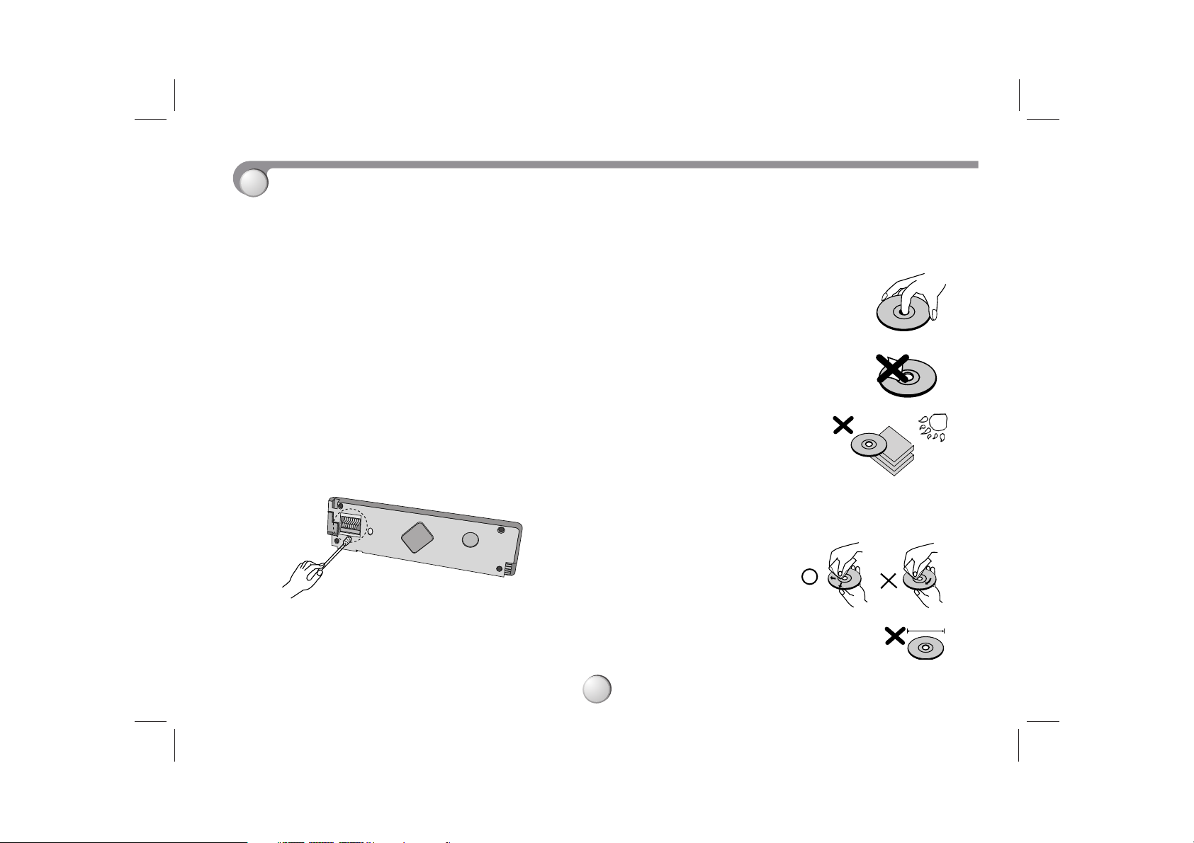
Notes on CD
• A defective or soiled disc inserted into unit can cause sound
to drop out during playback.
• Handle the disc by holding its inner and outer edges.
• Do not touch the surface of
the unlabeled side of the disc.
• Do not stick paper or tape
etc. on the surface.
• Do not expose the disc
to direct sunlight or
excessive heat.
• Clean the disc before playback. Wipe the disc from the center
outward with a cleaning cloth.
• Never use solvents such as benzine or alcohol to clean the
disc.
• This unit cannot be operated by 8cm disc
(using 12cm disc only).
Before Use
3
8 cm
4
Table of Contents
INTRODUCTION
Precautions . . . . . . . . . . . . . . . . . . . . . . . . . . . . . . . . . . . . . 2
Before Use. . . . . . . . . . . . . . . . . . . . . . . . . . . . . . . . . . . . . . 3
Table of Contents/Battery Installation . . . . . . . . . . . . . . . . 4
Remote control/Display Window . . . . . . . . . . . . . . . . . . . . 5
Front panel/Rear panel . . . . . . . . . . . . . . . . . . . . . . . . . . . . 6
Installation. . . . . . . . . . . . . . . . . . . . . . . . . . . . . . . . . . . . . . 7
Connection diagram . . . . . . . . . . . . . . . . . . . . . . . . . . . . . . 8
Connection . . . . . . . . . . . . . . . . . . . . . . . . . . . . . . . . . . . . . 9
Detachable Front Panel. . . . . . . . . . . . . . . . . . . . . . . . . . . 10
OPERATION
Basic operation . . . . . . . . . . . . . . . . . . . . . . . . . . . . . . 11-13
CD Basic Operation(CD/MP3 CD) . . . . . . . . . . . . . . . . . . . 14
CD Advanced Operation . . . . . . . . . . . . . . . . . . . . . . . . . . 15
Radio operation . . . . . . . . . . . . . . . . . . . . . . . . . . . . . . 16-17
CD changer Player(Optional) . . . . . . . . . . . . . . . . . . . . 18-19
REFERENCE
Specifications . . . . . . . . . . . . . . . . . . . . . . . . . . . . . . . . . . 20
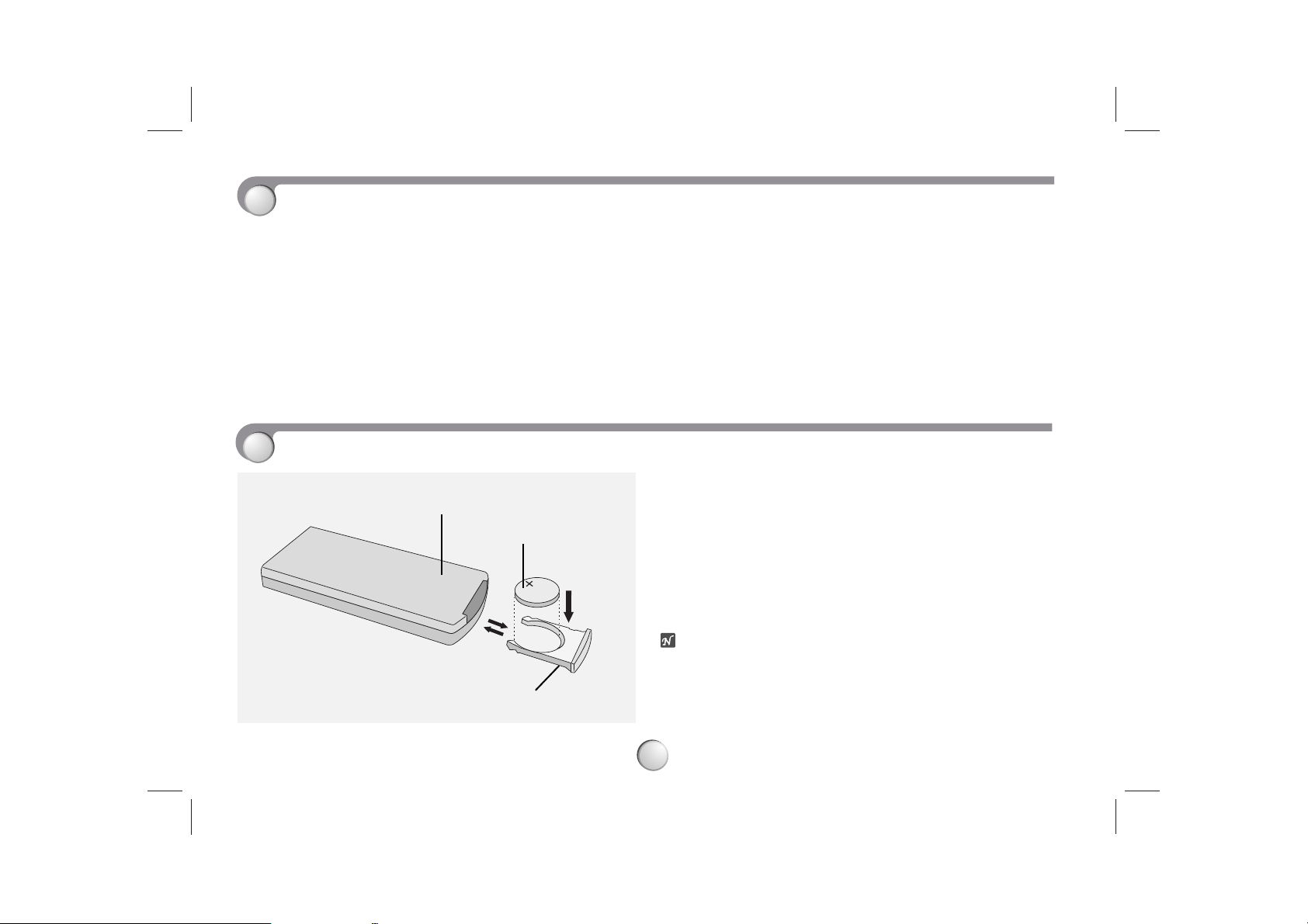
Battery Installation
1
2
3
1. LITHIUM BATTERY (CR2025)
2. REMOTE CONTROL BACK SIDE
3. BATTERY HOLDER
Basic Installation
a Remove the battery holder
b Install the battery on the battery holder
c Install the battery holder back into its original position
otes
• Battery type : Lithium battery (CR2025)
• Battery life : Approximately 6 months with normal use
b
a
c
5
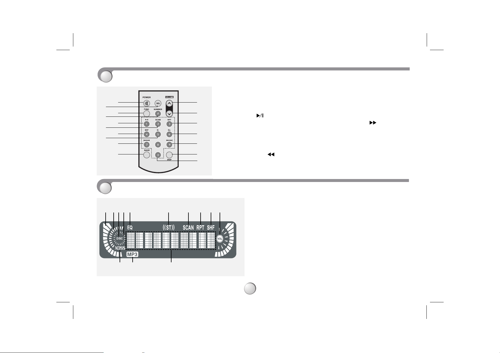
Remote Control
Display Window
1. POWER (PWR) / MUTE button
2. SELECTION (SEL) button
3. FUNCTION (FUNC) button
4. NUMBER button
5. PLAY/PAUSE ( ) button
6. INTRO SCAN (SCAN) button
7. SHUFFLE (SHF) button
8. DISC SELECTOR (D-) button
(Optional)
MP3 TRACK-10 button
9. CD SKIP/SEARCH ( ) button
SEEK/TUNE(-) button
10. BAND button
11. VOLUME UP button
12. VOLUME DOWN button
13. REPEAT (RPT) button
14. DISC SELECTOR (D+) button (Optional)
MP3 TRACK +10 button
15. CD SKIP/SEARCH ( ) button
SEEK/TUNE(+) button
16. • CLOCK (CLK) button
• DISPLAY (DISP) button
17. NUMBER (0 -9) button
1
3
5
7
9
10
11
12
13
14
15
16
4
6
8
2
17
1. SIGNAL LEVEL indicator
2. TUNING indicator
3. DISC indicator
4 DISC PLAY indicator
5. EQUALIZER (EQ) indicator
6. STEREO indicator
7. INTRO SCAN (SCAN)
indicator
8. REPEAT (RPT) indicator
9. SHUFFLE (SHF) indicator
10. VOLUME LEVEL indicator
11. MAIN DISPLAY SECTION
12. MP3 indicator
13. XDSS indicator
1 253 4 6 7 8910
13 12 11
CLK
6
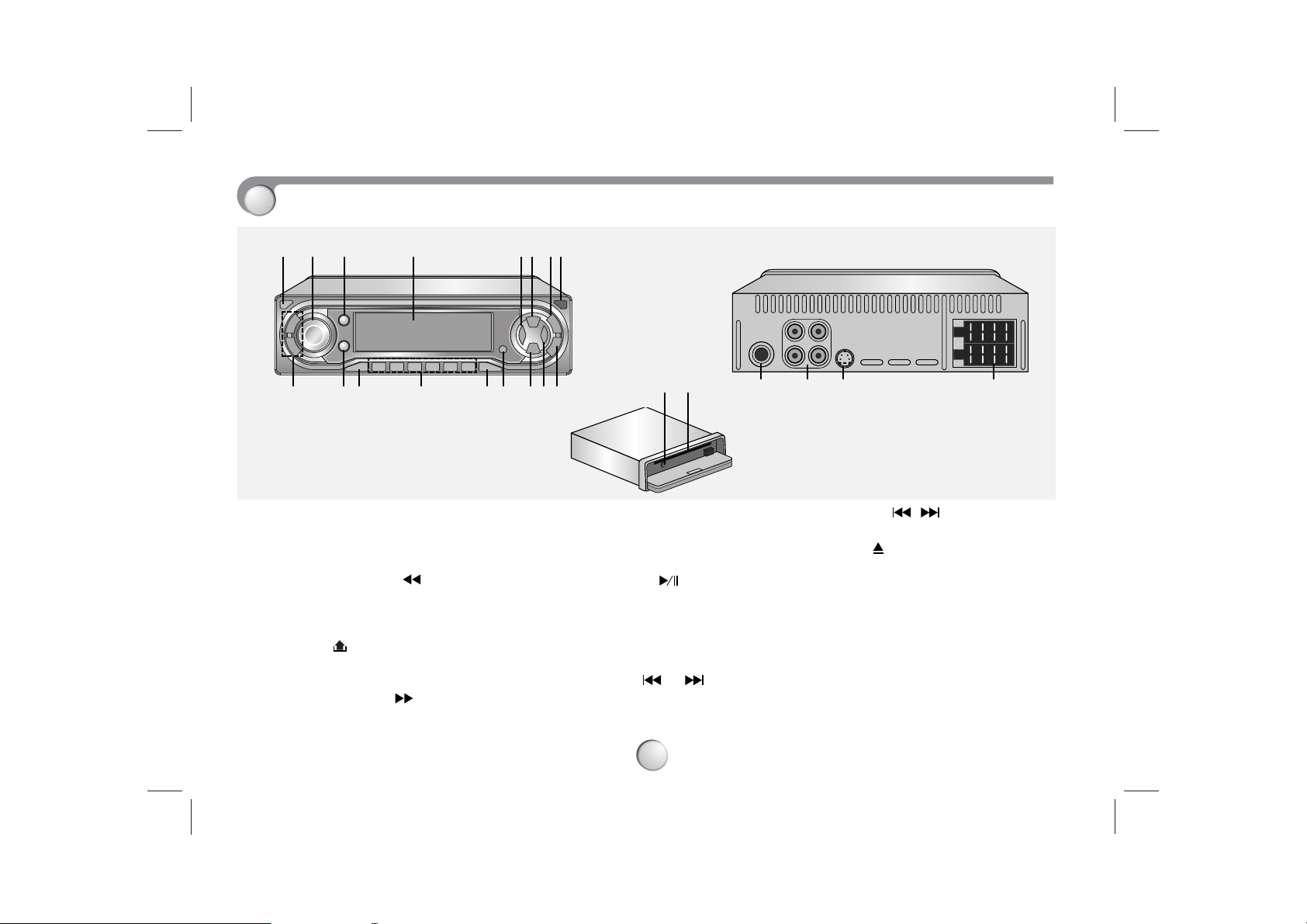
Front Panel/Rear Panel
1. POWER (PWR) button
2. CONTROL UP/DOWN dial
3. SELECTION(SEL) button
4. DISPLAY WINDOW
5. BACKWARD SEARCH ( )/TUNEbutton
6 MUTE button
7. XDSS button
8. RELEASE ( ) button
9. • CLOCK (CLK) button
• DISPLAY (DISP) button
10. FORWARD SEARCH ( )/TUNE+
button
11. AS/PS (auto store/preset scan) button
12. REMOTE SENSOR
13. EQUALIZER (EQ) button
14 • Preset Station buttons (1~6)
• CD PLAY/PAUSE ( ) button
• INTRO SCAN (SCAN) button
• REPEAT (RPT) button
• SHUFFLE (SHF) button
• DISC SELECTOR (D-/+) button
(Optional)
• MP3 TRACK 10 /10 (D-/+)
button
15. BAND button
16. FUNCTION (FUNC) button
17 • CD SKIP ( ) button
• SEEK (
+/-
) button
18. EJECT ( ) button
19. CD disc slot
20. ANTENNA JACK
21 LINE OUT JACK (Optional)
22. CD CHANGER JACK (Optional)
23. POWER/ SPEAKER CONNECTOR
12 43
16
56 78
17 15 13 12 1110 914
20 21 22 23
18 19
7
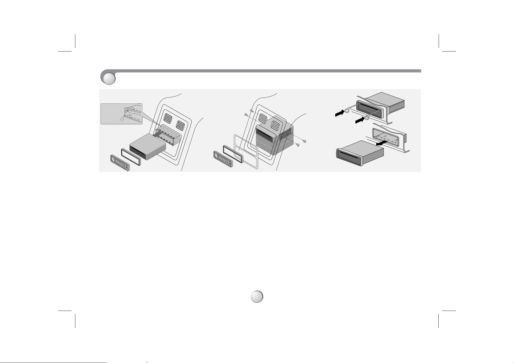
Installation
Basic Installation
Before installing, make sure that the
ignition-switch is set to OFF and remove
the terminal of the car battery to avoid
short-circuiting.
a Remove the existing receiver unit.
b Make the necessary connections.
c Install the installation sleeve.
d Install the unit in to the installation sleeve.
Removing existing receiver unit
If there is already an installation sleeve
for the receiver unit in the dashboard, it
must be removed.
ISO-DIN Installation
a Slide radio into ISO-DIN frame.
b Install screws removed from old
radio.
c Slide radio and frame into dash
opening.
d Install dash panel or adapter plate.
e Install trim ring to radio. The thin part
on trim ring must be positioned at the
bottom.
f Install faceplate by fitting right edge
into position then pushing left edge
closed.
When removing the unit from the
installation sleeve
If you need to remove the unit from the
installation sleeve, proceed as follows.
a Remove the rear supporter from the unit.
b Remove the front panel from the unit.
c Insert the lever into hole on one side
of the unit,and pull the lever toward
you. Do the same operation on the
other side and pull out the unit from
the installation sleeve.
5
4
3
1
2
6
Bend the claws
according to
the thickness
of the
dashboard
 Loading...