

Page 1
- 2-6 -
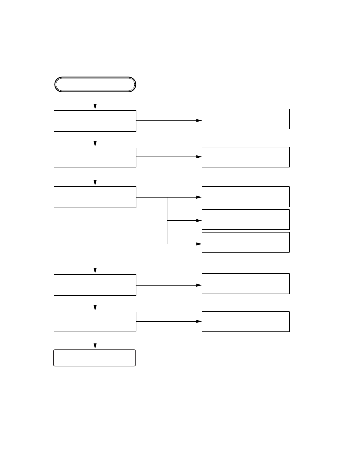
❏ ELECTRICAL TROUBLESHOOTING GUIDE
Any Key power on.
Is power turnd on?
DISC loading?
Does initial reading occur?
Can disc be played?
Is audio output supplied?
Check power supply circuitry.
Q808, Q809, Q802, IC401,
PIN13
Check loading supply circuitry.
Q505, Q506, Q507, IC401, CN505
Check laser circuitry.
Q501, IC501, IC503, IC504
Check focusing circuitry.
IC501, IC503
Check DISC.
Check tracking servo circuitry.
IC501, IC503
Check audio circuitry.
IC501, IC401, IC601, IC801
OK
YES
YES
YES
YES
YES
YES
NO
NO
NO
NO
NO
(1) No Power.
Page 2
- 2-7 -
YES
YES
YES
YES
YES
YES
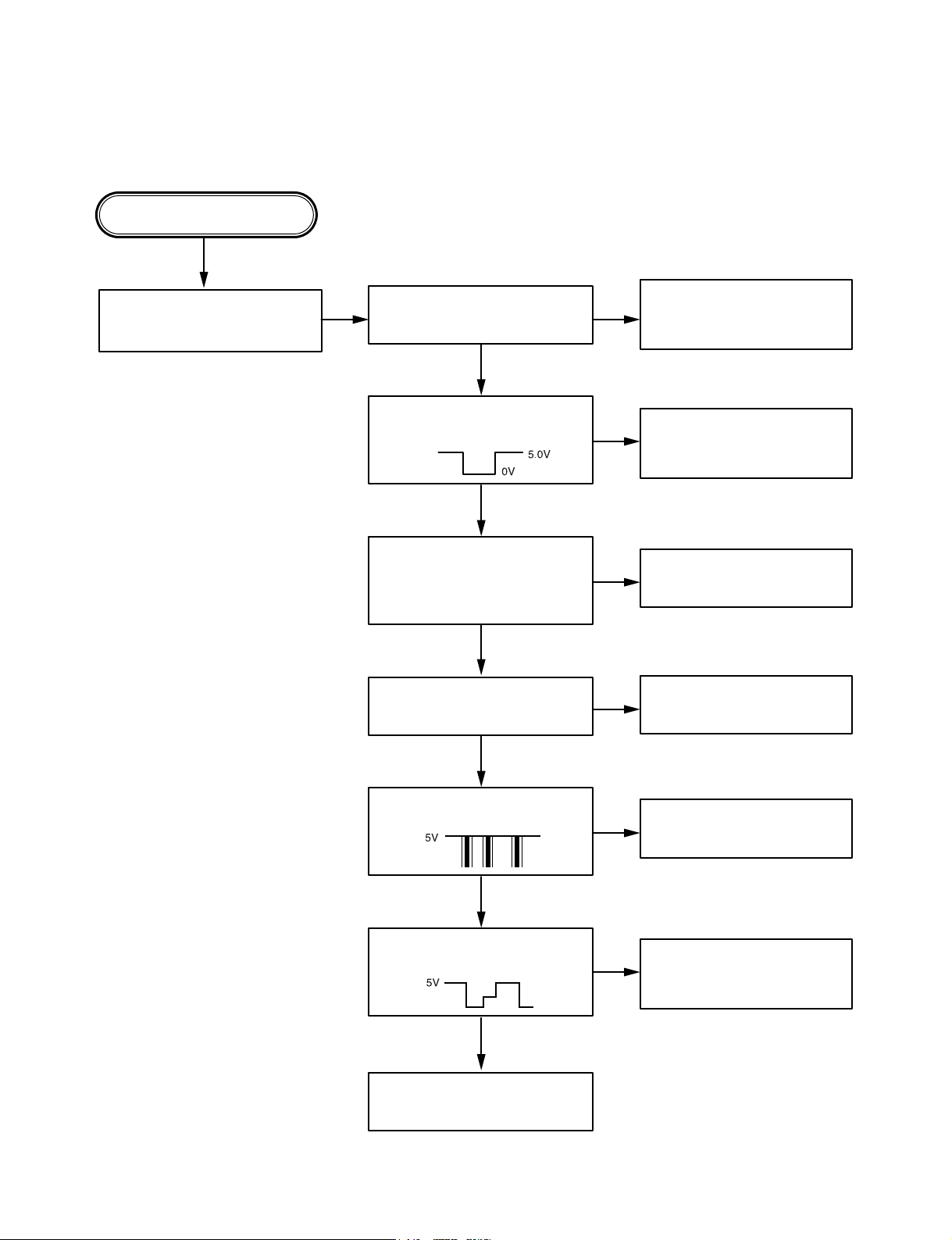
(2) LCD light abnornal.
Any Key power on.
(without DISC)
Do display LCD then light?
Check voltage in the power
supply circuitry.
Power supply circuitry
defective.
Q802, Q807, Q808, Q809
Reset circuit defective.
Q803,Q804 Surrounding
circuit defective.
X401, C410, C411 defective.
Q807, CN802 front PCB
pattern defective.
IC401, Pin45~48 front PCB
pattern defective.
IC901, Surrounding circuit
PCB pattern defective.
Is u-com IC401 reset circuit
normal? Pin53
Is u-com IC401 keyin Pin17, 18
5volt input?
Is u-com IC401 Pin45, Pin48
output waveform normal?
Is IC901 Com1, Com2, Com3
output waveform normal?
Display LCD connector defective.
Is u-com IC401X1, X2 terminal
pin 57.58 input?
OSC : 7.2MHz
NO
NO
NO
NO
NO
NO
NO
Page 3

- 2-8 -
(3) Initial reading is not carried out.
NO
NO
NO
NO
NO
NO
NO
NO
NO
NO
NO
NO
YES
YES
YES
YES
YES
YES
YES
YES
YES
YES
YES (with disc)
YES
YES
Slide motor moves
(Without disc)
Spindle motor turns
Does RF waveform appear?
IC501 Pin7
Check the Data transmission from
PN505 PIN7,8,20 to CD DSP
Check the Data transmission from
PN505 PIN19 to MICOM
Check the change of
SLPWMF Voltage
(IC503 PIN23)
Check the change of SL +,
SL - Voltage
(IC503 pin 13, 14)
Check the Voltage change of PN 505
PIN15 (7.5V)
Check the Voltage IC 501 PIN12
(1.4V~1.8V)
Defective connector
PN505
Defective IC 501
Defective connector
PN505
Defective MICOM
Defective connector
PN505
Defective IC501
Defective IC501
Defective IC503
Defective contact PN502
Defective PICK-UP
Laser light check A ?
focus coil drive wareform.
TRACKING ERROR wareform
Is rotation normal?
Defective IC501
Defective PICK-UP
Is there no dropout of RF signal?
Does FA+ waveform appear at
IC503 pin15?
Does TE waveform appear at
IC501 pin 11?
Page 4

- 2-9 -
NO
NO
NO
NO
NO
NO
When laser does not light.
Is “2.4V~3.4V” applied to pin 19 of IC 501?
( ➀ 3.4V ➁ 2.4V)
Is power supplied to laser Q501?
(Q 501 collector: about 1.8V)
Does laser current flow?
1.0V across R555
Is data transferred from
MICOM IC ?
Does voltage appear at IC
503 pin 13, 14?
Defective MICOM.
Defective MICOM.
Defective connector. (PN 501)
Defective IC 501, 503
Defective slide motor and/or
connector.
Defective LMT SW and/or
connector. (PN 502)
Defective Q 501 and/or laser.
Defective laser and/or
connector. (PN 501)
Did pickup return to
innermost circular?
Does it stop at inner pick
circular after shift?
Is defect output from LMT
SW applied to pin of
PN505?
R555 »1.0V
R555 «1.0V
YES
YES
YES
YES
OPEN
CLOSE
YES
YES
YES
YES
YES
YES
A
2
OV
Page 5

- 2-10 -
When laser light.
B
When SPINDLE motor dose not turn
C
NO
NO
NO
NO
YES
YES
YES
YES
Laser lights
Check the signal of
FOCUS SEARCH
(IC503 Pin 26)
Chekc the signal of IC503
pin 15, 16
Does FE signal appear?
(IC501 pin 9)
Does DRF signal appear? (IC 501 pin67)
Defective IC501
Defective IC503
Open activator and/or
connector
(PN501)
Degraded laser diode
Defective PICK-UP
YES
NO
NO
YES
Check the change of
SPPWMF Voltage
(IC503 pin26)
Check the change of SP +,
SP -, Voltage
(IC503 pin 11, 12)
Defective IC501
Defective IC503
Defective contact PN502
Defective PICK-UP
Page 6

- 2-11 -
(CH1)
(CH2)
❏ WAVEFORMS OF MAJOR CHECK POINT
1. HF signal (RF signal ) waveform
(IC501 pin 7) during normal play
2. EFM signal (IC501 pin 6)waveform
during Normal Play
3. Focus coil drive waveform(IC503 pin15)
• When focus search failed or there is no disc on the tray
• Focus coil drive waveform(IC503 pin26) and DRF(IC501
pin67) when focus search is accomplished
4. Tracking coil drive waveform and TE during track
traverse
(1) When time division is 20mS/Div.1V/Div.
(2) When time division 1mS/Div, 1V/Div
(During forward track traverse)
(3) When time division is 0.5nS/div.
(During backward Track Traverse)
5. Feed motor drive waveform(IC 503 pin14)
During normal play
CH1 : FOCUS COIL DRIVE
SIGNAL 2V/Div.
CH2 : DRF
CH1 : TRACKING COIL DRIVE
SIGNAL 2V/Div. (IC503 pin17)
CH2 : TRACKING ERROR(TE: IC501 pin11)
1V/Div.
(
(
(
CH1 : TRACKING COIL DRIVE (IC503 pin17)
SIGNAL 2V/Div.
CH2 : TRACKING ERROR (TE: IC501 pin11)
1V/Div.
(
CH1 : TRACKING COIL DRIVE (IC503 pin17)
CH2 : TRACKING ERROR (TE: IC501 pin11)
(
0.5V/Div.
500nS/Div.
(
1S/Div.
1V/Div.
(
1mS/Div.
1V/Div.
(
0.5V/Div.
5µS/Div.
(
2S/Div.
0.5V/Div.
OV
OV
OV
(CH1)
(CH2)
(CH1)
(CH2)
(CH2)
OV
OV
OV
OV
OV
OV
OV
OV
OV
 Loading...