

Page 1
Owner's Manual
TCC-9510
Cassette Player / Receiver with 4-Channel High Power
Output Flip Down Detachable Face Panel & ISO DIN
Mounting Chassis
BZ03
Page 2
WARNING : To reduce the risk of fire or electric shock, do
not expose this appliance to rain or moisture.
CAUTION : To prevent electric shock, match wide blade of
plug to wide slot, fully insert.
CAUTION-INVISIBLE LASER RADIATION WHEN OPEN AND
INTERLOCKS DFEATED, AVOID EXPOSURE TO BEAM.
HOW TO INSTALL & REMOVE THE APPARATUS
2
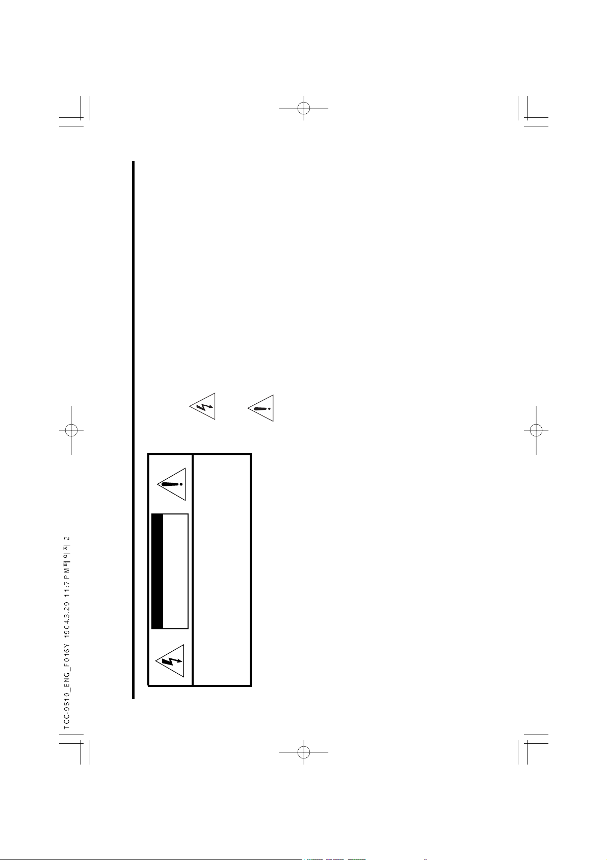
CAUTION
TO REDUCE THE RISK OF ELECTRIC SHOCK, DO
NOT REMOVE COVER (OR BACK) NO USER
SERVICEABLE PARTS INSIDE. REFER SERVICING
TO QUALIFIED SERVICE PERSONNEL.
RISK OF ELECTRIC SHOCK
DO NOT OPEN
WARNING
To avoid electrical shock; do not open the cabinet. Refer
servicing to qualified personnel.Shock hazard-do not
open.
CAUTION
Use of controls or adjustments or performance of
procedures other than those specified herein may result
in hazardous radiation exposure.
The lightning flash with arrowhead within an equilateral
triangle is intended to alert the user to the presence
of uninsulated “dangerous voltage” within the product’s
enclosure of sufficient magnitude to constitute a risk
to persons.
The exclamation point within an equilateral triangle
is intended to alert the user to the presence of
important operating and maintenance (servicing)
instructions in the literature accompanying the
appliance.
Page 3
10A
3
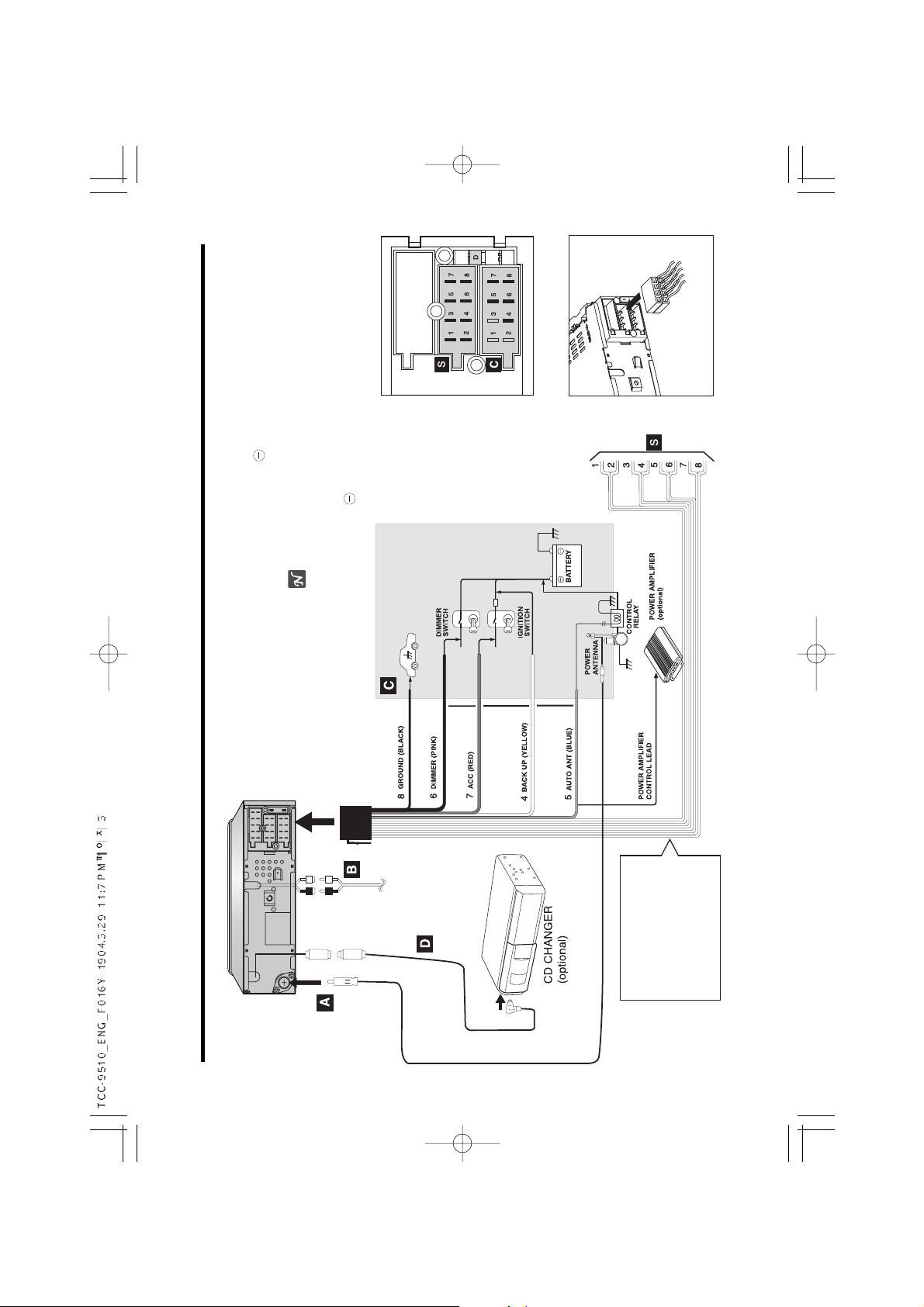
WIRING CONNECTIONS
1. VIOLET
2. VIOLET / BLACK STRIPE
3. GRAY
4. GRAY / BLACK STRIPE
5. WHITE
6. WHITE / BLACK STRIPE
7. GREEN
8. GREEN / BLACK STRIPE
Precaution on making connections
Before connecting, make sure that ignition switch is set to
OFF, and remove the terminal of the battery to avoid short
circuits.
Note
Make correct connections as illustrated in the connection
diagram.
Never use the cord of each speaker in common.
Page 4

4
WIRING CONNECTIONS
BLACK(Ground lead to be connected to vehicle(metal) body)
PINK(Dimmer lead to be connected to Dimmer switch of vehicle)
RED(ACC lead to be connected to the terminal from which the power is supplied when the ignition swich is set to ACC)
YELLOW(Battery lead to be connected to the back up terminal from which power is always supplied)
BLUE(To relay box for full automatic power antenna or power amplifier control lead. Power antenna load to be connected to the
terminal of the control relay switch for vehicles equipped with a power antenna. This lead is not used for vehicles with manual or
semiautomatic antennas)
From antenna
From power amplifier’s input jack( 2 channel or 4 channel : optional )
To the wiring of vehicle colors of leads
Connect the CD changer(optional)
Your car receiver works as control unil for a CD changer which you can buy. If not yet done, later.
The suitable cord shown on the scheme will be provided together with the CD changer.
2 - Speaker Connections
4 - Speaker Connections
LOUD SPEAKER
1. +Right Rear : VIOLET
2. - Right Rear : VIOLET/BLACK
3. +Right Front : GRAY
4. - Right Front : GRAY/BLACK
5. +Left Front : WHITE
6. - Left Front : WHITE/BLACK
7. +Left Rear : GREEN
8. - L e f t R e a r : GREEN/BLACK
Page 5
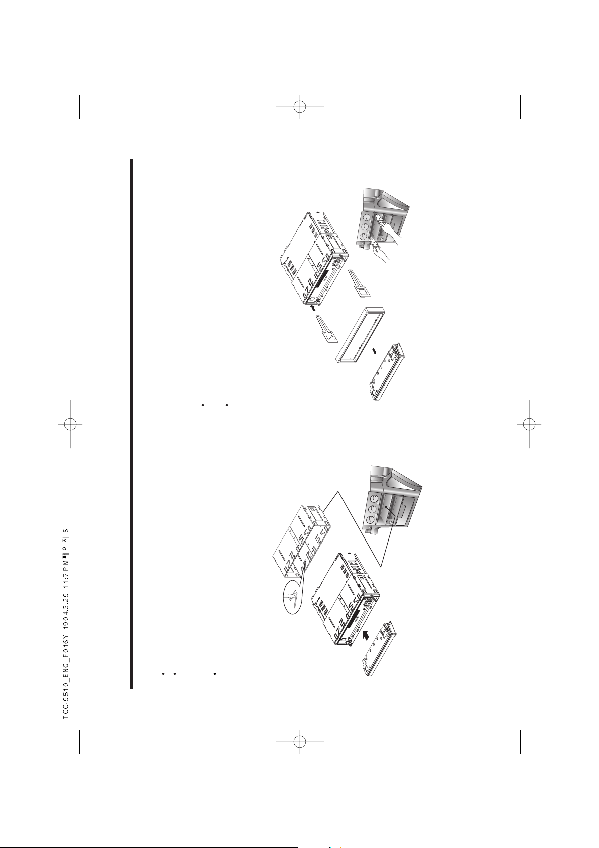
HOW TO INSTALL & REMOVE THE APPARATUS
5
NOTE !
Use only the supplied mounting hardware for safe and secure installation.
Please consult your nearest dealer if you get any problems with installation.
Press the open knob to open up the front panel and detach it by
pulling it towards you.
Insert the enclosed handles into the slits of the unit, as illustrated,
while pressing the handle lightly, then pull the unit out of the
holder.
HOLDER
Insert the holder into the car radio slot. Fasten the holder by
pulling and bending the tabs which are located around the
holder as illustrated.
Page 6

FRONT PANEL
6
Detaching the front panel
1. Press the open knob to open up the panel.
2. Holding the middle upper side of the panel, pull it straight out
towards the arrow direction.(See the figure)
3. The red lamp blinks to tell you that the front panel has been
detached.(It could be stolen) : Option
4. Keep the front panel in the supplied protection case.
Attaching the front panel
1. Holding the panel at its top and bottom
edges.
2. Attach one side of the panel lightly
first, then push the other side of the
panel into the unit.
3. Do not press the panel hard against the
unit. It can be attached by pressing it
lightly. And beware not to drop it.
Keep in mind:
If it works malfunction, take the panel off
and put it back again.
Do not touch the contact pins on the rear
of the front panel, this can cause contact
errors. If the contacts are not clean,
clean contacts with a cotton swab dipped
in alcohol.
Do not expose the front panel to direct
heat or cold.
Be careful not to splash juice or other soft drinks into the car audio.
Do not apply too much force. Otherwise, the panel may be
damaged.
Never take the front panel apart.
When front panel is open, beep sound once after 57 seconds,
then beep sound twice after 58 seconds and power turns off at 1
minute.
Page 7

7
FUNCTION DESCRIPTION, CONTROLS
1. POWER
ON/ OFF(PWR)
2. VOLUME UP/ DOWN
3. BAND
4. AUDIO SELECTOR
5. EQ
6. MODE
13. AUT(AUTO TRAVEL PRESET)
14. TUNE(AUTO/ MANUAL)
15. TUNING & TRACK UP/ DOWN (TUN / )
16. SCAN
17. DISPLAY (DSP)
18. OPEN BUTTON
7. DIR/MUTE
8. LCD
9. INTRO SCAN(INT)
10. REPEAT(RPT)
11. PRESET STATION
12. SUPER-BASS/LOC
Page 8

RADIO
8
1. POWER ON/OFF (PWR )
To switch the audio system on/off, press power
button lightly.
Simultaneously, the system memorizes all
information about its current setting, and restores
the information when you turn the system on by
pressing the power on/off button again.
You can also turn the system on by pressing BAND or MODE
button instead of power button.
2. SOUND CONTROL (VOLUME, )
Rotate outer SEL button clockwise/counterclockwise to
increase/decrease the VOLUME, BASS, TREBLE, BALANCE,
FADER, depending on what you select using the audio selector.
3. AUDIO SELECTOR (SEL, )
Pressing the audio select button, you can adjust
BASS, TREBLE, BALANCE, FADER and
VOLUME. Select the item you want to adjust by
pressing the audio selector repeatedly. Adjust the
selected item within 5 seconds. (After 5 seconds
the function will again serve as the volume
control.)
4. TUNING UP / DOWN CONTROL ( )
During the radio mode :
Rotate the Tune button
clockwise / counterclockwise to choose the radio
station which you want to listen to step by
step.Press the Tune button to the higher or lower
station. The sound will be muted during seeking
automatically.
In case of clock mode :
This button is to hour/minute up-adjust.
5. PRESET STATION (Button 1-10, )
Any station may be preset into these buttons by simply pressing
and holding the buttons down for 2 seconds. Up to 20FM (10 in
FM1, 10 in FM AUT) 20 FM OIRT (10 in FM OIRT, 10 in FM OIRT
AUT) and 30AM stations (10 in MW1, 10 in MW2 and 10 in MW
AUT) can be assigned to the preset station buttons.
6. BAND CONTROL (BAND, )
Step cyclically through the tuning bands in the order :
FM-1
FM(OIRT) MW-1 MW-2 FM-1
Page 9

RADIO/SOUND/ DISPLAY
9
7. AUTO TRAVEL PRESET (AUT, )
Press the AUT button within 1.5 seconds, you can
change the radio mode to the AUT function that
operates all over the radio band. The display will
show you the message “AUT”. To return, press
the AUT button within 1.5 seconds again.
Press the AUT button for more than 1.5 seconds it
starts to search for the 10 strongest FM or AM stations of the
region where you are driving to be stored. To return to the stations
you manually set, press the band button lightly.
8. Super-BASS (SUP-B, LOC, )
Press this button to select boosting the bass
sound or normal sound. The message “S-BASS”
appears on the display while you enjoy the BASS
boost. To cancel, press this button again.
LOCAL STATION (LOC, )
When pressed this button for more than
1.5seconds, it displays the message “LOC”. This is used to
change the tuning stop level during search. The LOCAL mode is
established when the button is pressed to its ON position. At this
position, stations with weak transmissions signals are skipped.
This function makes it possible to scan quickly all those stations
with stable reception. Press the button once more than 2 seconds
again to its OFF position to scan stations with weak signals.
9. MUTE ( )
Press this button to mute the sound temporarily. To cancel the
mute mode, press this button again.
10. EQ ( )
Press the EQ button and than, rotate volume to
select from the different sound effects of Pop,
Rock, Classic and Flat. Adjust the level of Treble
and Bass in EQ-User’s mode only.
11. SCAN (SCAN,
)
When this switch is pressed during broadcast reception, scan
tuning will start, stations are tuned in automatically and held 5
seconds, after which scanning resumes until the next station is
located. Pressing this switch again will stop scan tuning.
12. DISPLAY CONTROL (DSP,
)
When pressed belower than 1.5 seconds.
present clock is displayed.
another key is not pressed during 5 seconds, it
is changed priority display states.
(1) In Radio Mode
FREQ (CLK)
(2) In TAPE Mode
TAPE FREQ (CLK)
During clock displayed
Press the DSP button and simulta-
neously turn the Tune button to
adjust clock.
(T-UP: Minutes, T-DN : Hour)
Hour Minute
Page 10

CASSETTE PLAYER
10
Listening to a tape
Fast winding the tape ( , )
During playback,
rotate the Tune button clockwise / counterclockwise to rewind/ fast
forward.
To start playback during fast forwarding, press the DIR button
again.
13. TAPE Ejection
Open the front panel by pressing “OPEN” ( ).
Press the “ ” button to remove your tape from the unit.
Rewind Fast-forward
Open the front panel by pressing the open ( ) button.
Insert a cassette tape.
Close the front panel.
Play will start automatically.
If a tape is already inserted, press the DIR button.
Page 11

CASSETTE PLAYER
11
14. INTRO SCAN (INT, )
Press the “INT” button, it displays “INTRO” and
then it starts to play the first 10 seconds for songs.
15. REPEAT Function (RPT, )
If you want to listen to a song repeatedly, press
the RPT button, then “RPT” appears on the
display. This function will operate right after the
song which you are listening. Press the button
once again, the function returns to normal play
mode.
16. DIR (DIR,
)
Press this button briefly you can change the side
of the tape that is playing.
Press this button more than 2 seconds, to mute
the sound temporarily.
To cancel the mode press again.
To go to the beginning of a desired track
17. Automatic Music Search (AMS)
During playback, press the TUN button once, then
rotate the TUN button clockwise / counter-
clockwise.
Then the Tape will fast forward/rewind auto -
matically to play next or previous song (Track).
Note:
The AMS function may not work when
the blanks between tracks are shorter than 4 seconds
there is noise between tracks
there are long section of low volume or quiet.
The AMS enables you to locate the beginning of the next
song(track) or the previous song(track).
Page 12

12
4. RANDOM FUNCTION (RDM,
If you want to enjoy the songs in a random order, press this button.
Then “RDM” appears on the display with playing in a random order.
Pressing the button once again the function returns to the normal
play mode.
If you want to enjoy the CD in a random order,
Press this button more than 2 seconds.
Then
RDM DISC appears on the display with playing in a random
order.
5. DISC SELECTOR (D- / D+, )
You can change the discs pressing the “D-” or “D+”
In case of inserting 6 disc changer.
DISC-1 DISC-2 DISC-3 DISC-4 DISC-5 DISC-6
TRACK UP/DOWN Control. (TUN / )
- Rotate the TUN button clock wise / counter clock
wise to choose the tracks which you want to listen.
1. CDC MODE SELECTOR (MODE, DIR, )
Press the MODE button to change to CD changer mode.
If you press DIR button, CD sound will be muted (PAUSE mode).
To play during the pause press this button again.
2. INTRO SCAN (INT, )
Press the INT button to know what songs are on the CD during
playback, then it starts to play the first 10 seconds of the tracks
which are from the next song to the last one, while the “INT”
appears on the display.
Press the INT button once more to listen to the song you want to
hear while this function is operating, then “INT” disappears.
Press the INT button more than 2 seconds to know what CD are
on the CDC during playback, then it starts to play the first 10
seconds of the CD which are from the next CD to the last one,
while the “INT DISC” appears on the display.
3. REPEAT FUNCTION (RPT, )
Press the Repeat button to play the same track continuously.
Press the Repeat button more than 2 seconds to play the same
CD continuously.
DIR(CDC)
INTRO SCAN
REPEAT
RANDOM
DISC SELECTOR(D-/D+)
MODE
OPTION : CD - CHANGER
Page 13

SPECIFICATION
13
GG
GG
EE
EE
NN
NN
EE
EE
RR
RR
AA
AA
LL
LL
Power supply 12 - 15V DC
Speaker impedance 4 or 8 ohm
Output Power Maximum 50W x 4CH
Current Drain Max. 10A
NOTE !
Designs and specifications are subject to change
without notice for improvement.
TT
TT
UU
UU
NN
NN
EE
EE
RR
RR
SS
SS
EE
EE
CC
CC
TT
TT
II
II
OO
OO
NN
NN
FM OIRT MW
Frequency Range 87.5-108MHz 65-74MHz 522-1620KHz
Stereo separation 30dB 30dB
Signal to Noise ratio 55dB 55dB 50dB
Frequency step (Manual)
50KHz 10KHz 9KHz
TT
TT
AA
AA
PP
PP
EE
EE
SS
SS
EE
EE
CC
CC
TT
TT
II
II
OO
OO
NN
NN
Wow and Flutter 0.35%
Signal to Noise ratio 50dB
Channel Separation 35dB
Frequency Response 63Hz-10kHz(
3dB)
Tape Speed 4.75cm/sec
Dimension
(W H
D)
178 50 152.5(
Weight 1.4 Kg
The working life of this product is 7 years since the date of
purchase.
Page 14

P/N:3828R-F016Y
 Loading...