

Page 1
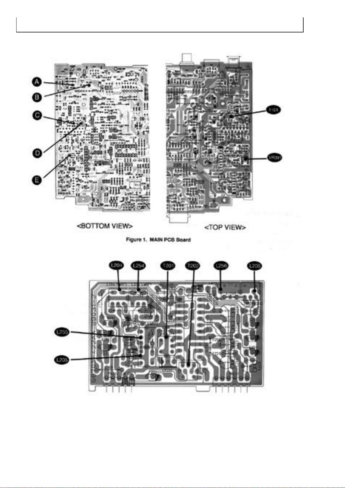
4. ADJUSTMENTS
1. Test & Adjustment point
Figure 2. RF PCB Board
- 6 -
Page 2
- 7 -
GND
EXT
MODE
OUT
Stereo modulator
AUDIO OSC
SG
Unit
ANT
Jack.
IN
OUT
SCOPEVTVM
PRE OUT
(Black Lead)
(Red Lead)
(Yellow Lead)
Power Supply
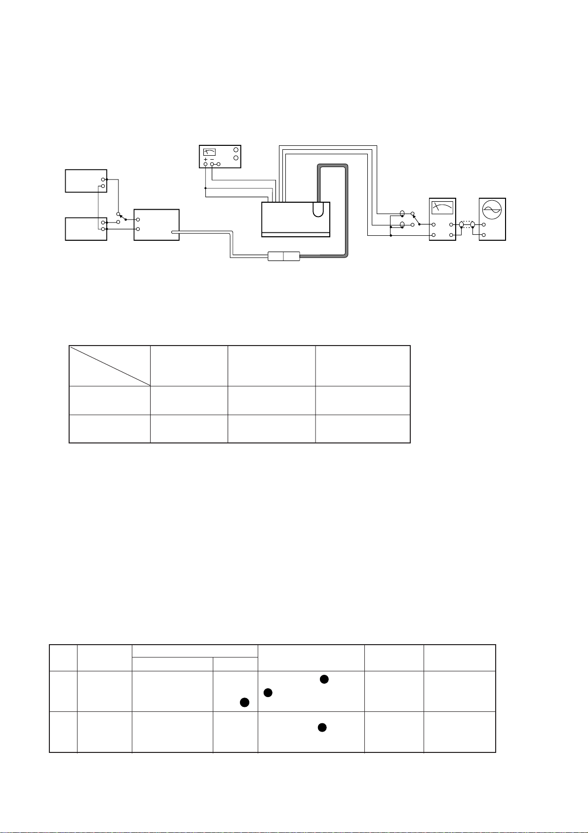
Figure 3.
2. FM Adjustment
(1) The impedance of FM antenna terminal is 75½.
Therefore, connect coaxial cable (3C-2V etc.) between FM SG and antenna terminal when wiring.
(2) There are two kind in indication of FM SG output attenuator.
1) Attenuator with marking of 75½ openÉopen indication type.
2) Attenuator with marking of 75½ load or close É load or close indication type.
(3) FM SG output level in this FM adjustment are described as open indication type. The left table
shows relations among FM SG attenuator indication (dB), available power ratio (dBf) and antenna
terminal voltage (dB/µV) in each indication type.
Notes:
1. BAND Switch..................................................................................................................................FM
2. BALANCE .................................................................................................................................Center
3. TREBLE/BASS .........................................................................................................................Center
4. Connect as shown in figure 3.
5. Refer to figure 1~2 for Adjustment Points.
Item
FM SSG Available Antenna
Attenuator Power Terminal
Type
Indication Ratio Voltage
Open indication 0dB 5.2dBf 6 dB/µV
type 60dB 65.2dBf 66dB/µV
Load or close 0dB 11.2dBf 12dB/µV
indication type 54dB 65.2dBf 66dB/µV
STEP SUBJECT
FEED SIGNAL
MEASURE OUTPUT ADJUSTMENT ADJUST FOR
Discriminator
MPX
Adjustment
98MHz 60dB
22.5kHz Dev.
FM SSG
98MHz 60dB
75kHz Dev
FM SSG
ANT Jack
or
Point
Same as
above
A
Between Point & Point
, DC Volt Meter.
Between Point ,
Frequency Counter
EDC
T101
VR301
1
2
DC 0V ±10mV
76kHz ± 50Hz
FROM TO
Page 3
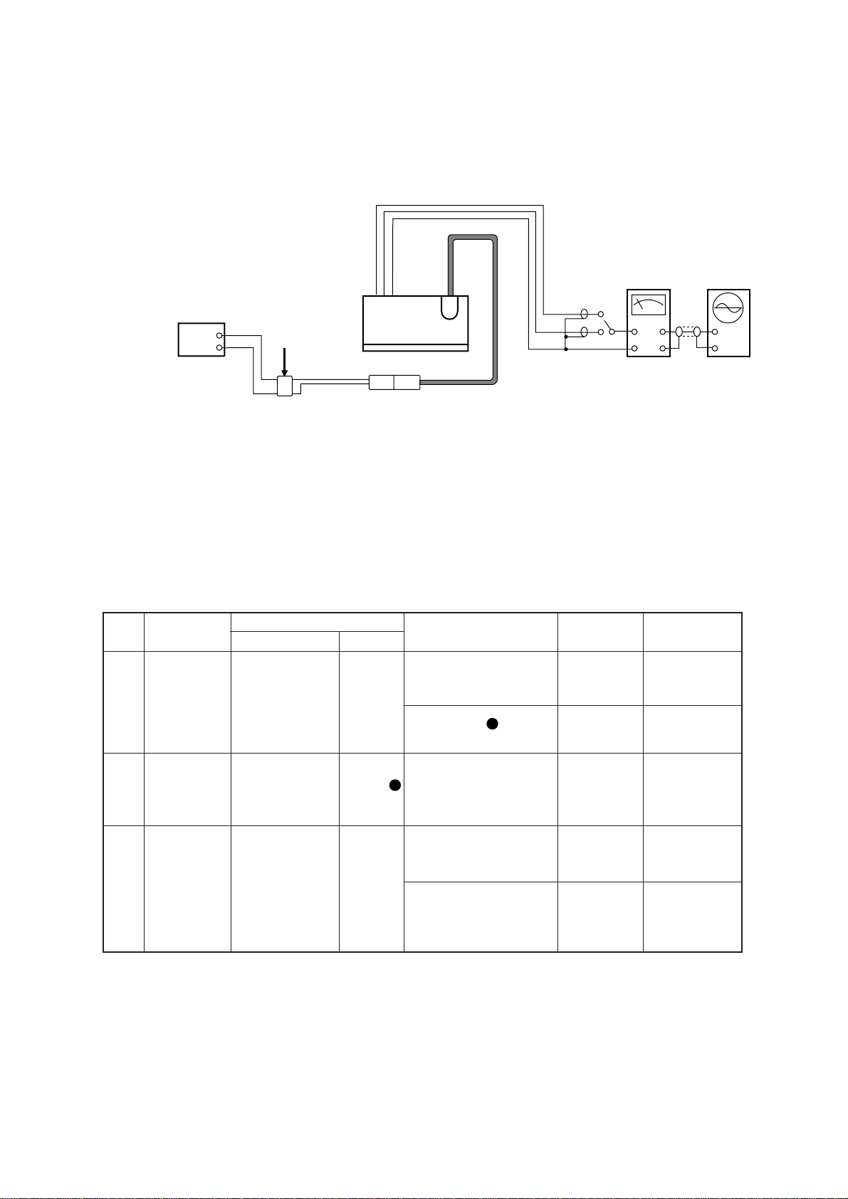
3. AM(MW) Adjustment
Notes:
1. BAND Switch.........................................................................................................................AM(MW)
2. Connect as shown in figure 4.
3. Refer to figure 1~2 for Adjustment Points.
- 8 -
STEP SUBJECT
FEED SIGNAL
MEASURE OUTPUT ADJUSTMENT ADJUST FOR
FROM TO
520 or 522kHz
Tuning Voltage
Adjustment
IF Coil
Adjustment
600kHz
or 603kHz
RF Adjustment
No Input
600kHz or 603kHz
ANT input, 30dB,
400Hz (30% MOD)
SSG.
600kHz or 603kHz
ANT input, 30dB,
400Hz (30% MOD)
SG.
ANT Jack
or Point
Same as
above
LCD Display
(Reception Frequency)
Between Point and GND,
DC Volt Meter
Output L or R ch,
VTVM & Oscilloscope
LCD Display
(Reception Frequency)
Output L or R ch,
VTVM & Oscilloscope
TUNE + / Button
L206
T201 & T202
TUNE + / Button
L204 & L205
1
2
3
520 or 522kHz
DC 1.2V ± 0.05V
Max. Output
600 or 603kHz
Max. Output
Unit
ANT
Jack.
IN
OUT
SCOPEVTVM
PRE-OUT
ASG
AM Dummy ANT
OUT
Figure 4.
A
B
Page 4
- 9 -
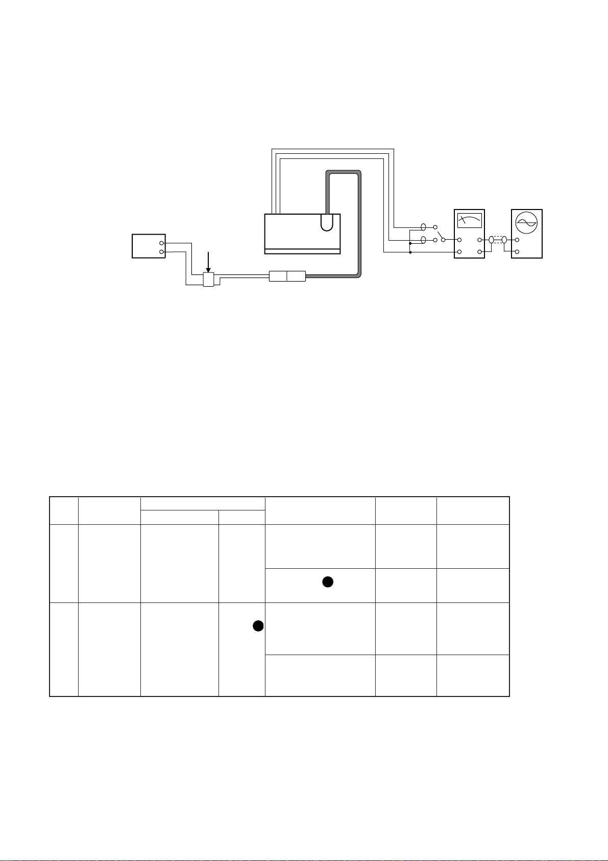
4. LW Adjustment(Optional)
Notes:
1. BAND Switch...................................................................................................................................LW
2. Connect as shown in figure 5.
3. Refer to figure 1~2 for Adjustment Points.
STEP SUBJECT
FEED SIGNAL
MEASURE OUTPUT ADJUSTMENT ADJUST FOR
144kHz
Tuning Voltage
Adjustment
150kHz
RF Adjustment
No Input
150kHz
ANT input, 30dB,
400Hz (30% MOD)
SSG.
ANT Jack
or Point
LCD Display
(Reception Frequency)
Between Point and GND,
DC Volt Meter
LCD Display
(Reception Frequency)
Output L or R ch,
VTVM & Oscilloscope
TUNE + / Button
L256
TUNE + / Button
L254 & L255
1
2
144kHz
DC 1.2V±0.05V
150kHz
Max. Output
Unit
ANT
Jack.
IN
OUT
SCOPEVTVM
PRE-OUT
SSG
AM Dummy ANT
OUT
Figure 5.
FROM
TO
A
B
Page 5
- 10 -
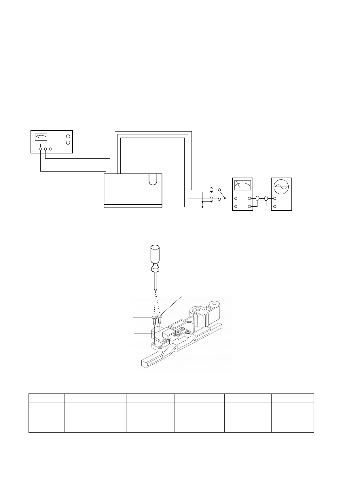
5. Cassette Deck Adjustment
(1) Before this adjustment, clean PLAYBACK head surface.
(2) For this adjustment, use test tape MTT-114.
(3) VOLUME.......................................Center
(4) BALANCE ....................................Center
(5) TREBLE/BASS .............................Center
(6) Connect as shown in figure 6.
Unit
ANT
Jack.
IN
OUT
SCOPEVTVM
PRE-OUT
GND
Power Supply
(Red Lead)
(Black Lead)
(Yellow Lead)
R-CH
L-CH
Forward Head Azimuth
Adjustment Screw
Head
Reverse Head Azimuth
Adjustment Screw
Screw Driver
SUBJECT MEASURE OUTPUT SETTING ADJUSTMENT ADJUST FOR REMARKS
P.B. Head
Adjustment
L-CH, R-CH, VTVM and
Scope See figure 6.
Playback (FWD &
REV) the TEST
TAPE MTT-114
Adjust the
azimuth
adjusting screw
(in figure 7).
MAX. Output
both channels
on FWD and
REV PLAY
After this
adjustment, lock
the screw with
paint.
Figure 7.
Figure 6.
 Loading...