

LG TB-H488RSS5 Service Manual

Ceiling Duct Type
Air Conditioner
SERVICE MANUAL
MODELS:
TB-H488RSS5

Contents
Functions ..................................................................................................................................3
Product Specifications .............................................................................................................5
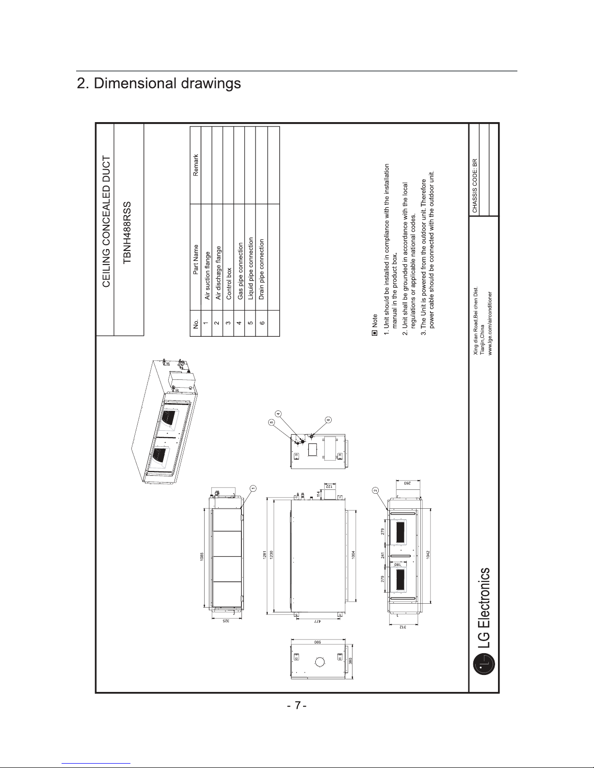
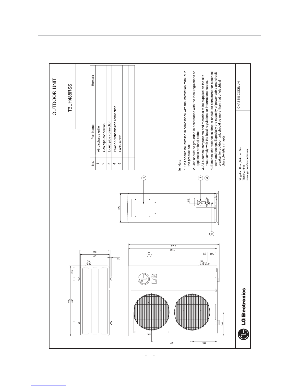
Dimensions ..............................................................................................................................11
Refrigeration Cycle Diagram ..................................................................................................31
Wiring Diagram .......................................................................................................................35
Operation Details ....................................................................................................................51
Installation of Indoor, Outdoor Unit ......................................................................................54
Test running ............................................................................................................................66
Optional Operation .................................................................................................................68
External Static Pressure & air Flow ......................................................................................70
3-way Valve .............................................................................................................................71
Cycle ........................................................................................................................................74
Cycle Troubleshooting Guide ................................................................................................78
Electronic Parts Troubleshooting Guide ..............................................................................79
Electronic control device .......................................................................................................82
Exploded View and Replacement Parts List ........................................................................83
–2–
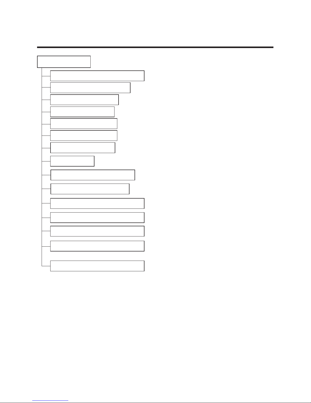
Functions
Indoor Unit
Operation ON/OFF by Remote controller
Sensing the Room Temperature
Room temperature control
Starting Current Control
Time Delay Safety Control
Indoor Fan Speed Control
Soft Dry Operation Mode
Auto Operation(Auto Change Over)
Deice (defrost) control (Heating)
Auto Restart
–3–
Hot-start Control (Heating)
• The indoor fan does not start until the evaporator piping
temperature will be reached at 28°C.
High head height Drain pump(Optional)
• A standard drain-head height of up to 700mm is possible.
Central Control(Optional)
•
It is operating individually or totally by central control function.
Group Control(Optional Wiring)
Radio Frequency Control (Optional)
•
Each controller can control 16 units and 8 controllers can be connected.
•
It operates maximum 16 units with the help of only one wired remote
controller and each unit can be randomly started to prevent overcurrent.
• Room temperature sensor. (Thermistor)
•
Maintains the room temperature in accordance with the Setting Temperature.
• Indoor fan is delayed for 5 seconds at the starting.
• Restarting is inhibited for approx. 3 minutes.
• High, Medium, Low
• Intermittent operation of fan at low speed.
• Although the air-conditioner is turned off by a power failure, it is restarted automatically previous operation mode after power supply.
• The setting temperature and desired operation mode are automatically set by fuzzy rule.
• Both the indoor and outdoor fan stop during defrosting.
• Hot start after defrost ends.
–4–
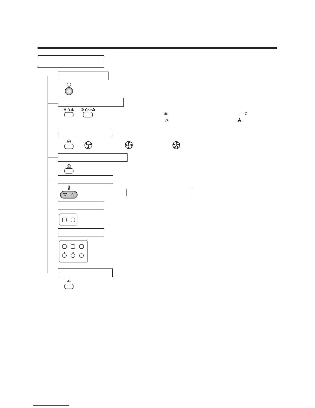
Remote Controller
Operation ON/OFF
Operation Mode Selection
Fan Speed Selection
Room Temperature Display
Temperature Setting
Setting the Timer
Weekly Program
(Cooling
model only)
(Heating
model only)
(Low) (Med) (High)
Cooling Operation Mode ( )
Heating Operation Mode ( ) Auto Operation Mode ( )
Soft Dry Operation Mode ( )
Fan Operation Mode
HIMEDLO
Program Holiday
SET/CLR
MinHour
Week
Timer CancelTimer Cancel
: High:39°C ļ LOW:11°C
: Only the Fan is in operation.
Cooling Heating
Down to 18°C
Up to 30°C
Down to 16°C
Up to 30°C
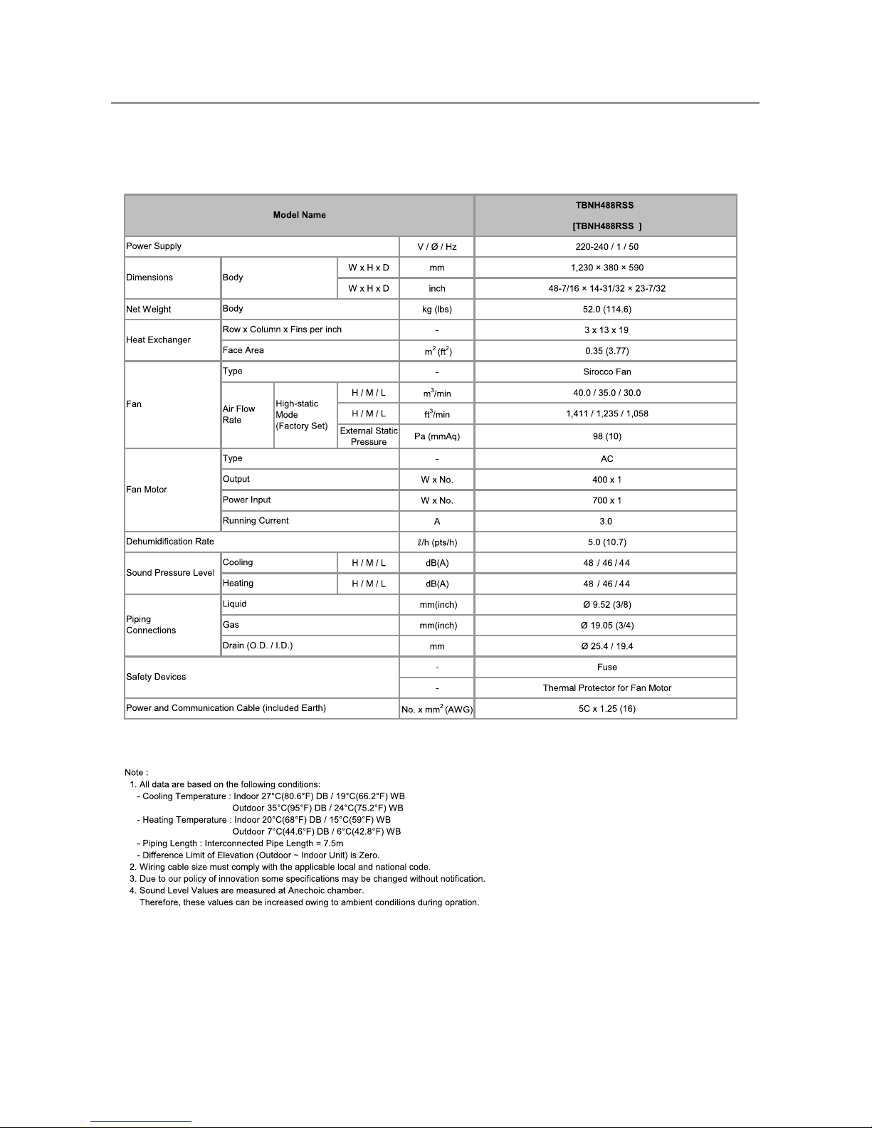
1. Specifications
1.1 Indoor unit
-5-
5
5
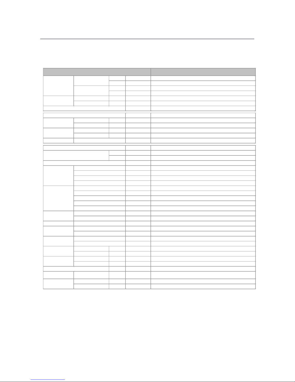
1. Specifications
1.2 Outdoor Unit
-6-
Note :
1. All data are based on the following conditions:
- Cooling Temperature : Indoor 27°C(80.6°F) DB / 19°C(66.2°F) WB
Outdoor 35°C(95°F) DB / 24°C(75.2°F) WB
- Heating Temperature : Indoor 20°C(68°F) DB / 15°C(59°F) WB
Outdoor 7°C(44.6°F) DB / 6°C(42.8°F) WB
- Piping Length : Interconnected Pipe L
ength = 7.5m
- Difference Limit of Elevation (Outdoor ~ Indoor Unit) is Zero.
2. Wiring cable size must comply with the applicable local and national code.
3. Due to our policy of innovation some specifications may be changed without notification.
4. Sound Level Values are measured at Anechoic chamber.
Therefore, these values can be increased owing to ambient conditions during opration.
TBUH488RSS5
Rated kW 14.0
Rated Btu/h 48,000
Rated kW 15.2
Rated Btu/h 52,000
Cooling Rated kW 5.30
Heating Rated kW 5.00
W / W 2.65 / 3.05
V / Ø / Hz 380-415 / 3 / 50
Cooling Rated A 9.0
Heating Rated A 8.0
Cooling Max. A -
Heating Max. A -
Wiring Connections Power Supply Cable (included Earth)
No. x mm
2
(AWG)
5C x 3.5 (12)
- White
W x H x D mm 900 × 1,165 × 370
W x H x D inch 35-7/16 × 45-7/8 × 14-9/16
kg (lbs) 95.0 (209.4)
- Scroll
Model x No. SB061YAB x 1
- Three Phase Induction Motor
W x No. 4,050 x 1
- R22
g (oz) 3,600 (141.1)
m (ft) 7.5 (24.6)
g/m (oz/ft) 65 (0.76)
- Capillary
- SUNISO 4GSI or NM56M
cc
x No. 1,650 x 1
- (2 × 26 × 17) × 2
- Propeller
m
3
/min x No.
52.5 x 2
- AC
W x No. 77 x 2
Cooling Rated dB(A) 61
Heating Rated dB(A) 61
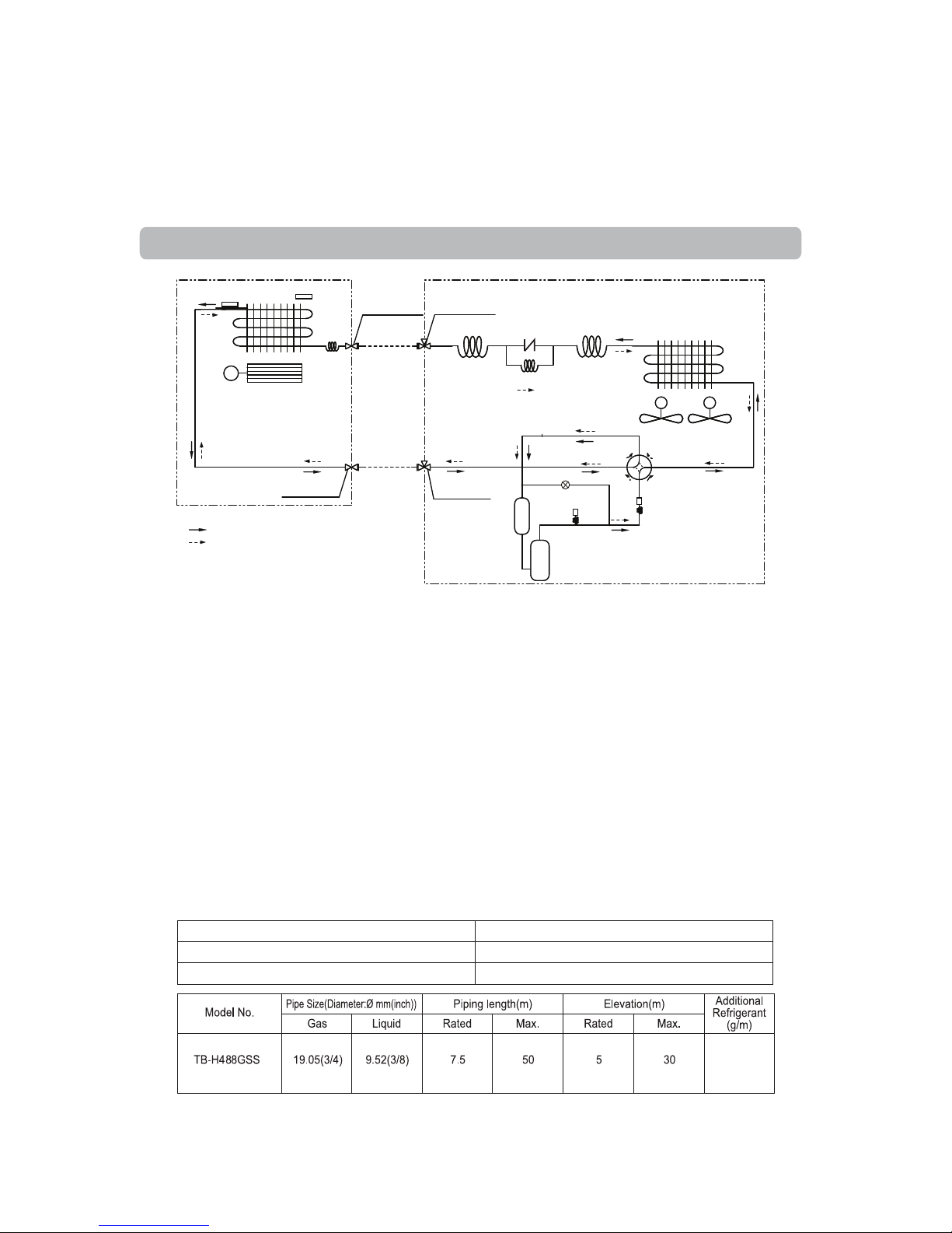
Liquid Outer Dia. mm(inch) Ø 9.52 (3/8)
Gas Outer Dia. mm(inch) Ø 19.05 (3/4)
Max. m (ft) 50 (164)
Maximum Height
Difference
Outdoor Unit ~ Indoor Unit Max. m (ft) 30 (98.4)
Cooling Min. ~ Max.
℃ DB (℉ DB)
21 (69.8) ~ 54 (129.2)
Heating Min. ~ Max.
℃ DB ( ℉ DB)
-5(23.0) ~ 24 (75
.2)
Heat Exchanger (Row x Column x Fins per inch) x No.
Operation Range
(Outdoor Temperature)
Fan
Fan Motor
Sound Pressure Level
Pipin
g Connections
Pipi
ng Length
Type
Air Flow Rate
Type
Type
Dimensions
Casing Color
EER / COP
Type
Refrigerant Oil
Type
Precharged Amount
Charged volume
Power Input
Running Current
Starting Current
Power Supply
Output
Compressor
Refrigerant
Net Weight
Motor type
Motor Output
Chargeless-Pipe Length
Mo
del
Additional Charging Volume
Control
Outdoor unit
Capacity
Cooling
Heating
5
8
5
–9–
Description
PCB Connector
CN-PIPE
CN-ROOM
Model No.: TB-H488RSS5
High
Pressure
Switch(By-Pass)
High
Pressure
Switch
Compressor
MM
Outdoor Unit
Indoor Unit
Ø9.52 / 3 way
Flare Connection
Ø19.05 / 3 way
Flare Connection
Ø19.05 / 2 way
Flare Connection
Ø9.52 / 2 way
Flare Connection
: Cooling
: Heating
←
BY-PASS
4 way
Valve
Accumulator
Condenser out
Capillary Tube
Cooling
Capillary Tube
Evaporator in
Capillary Tube
Heating
Capillary Tube
MM MM
Thermistor for
Suction Air temperature
Thermistor for evaporator
outlet temperature
Thermistor for evaporator outlet temperature
Thermistor for Suction Air temperature
5
65
3.Piping diagrams
Operation Details
(1) The function of main controls/controller
1. Time Delay Safety Control
• 3min
...
The compressor is ceased for 3minutes to balance the pressure in the refrigeration cycle.
(Protection of compressor)
• 30sec
...
The 4-way valve is ceased for 30sec. to prevent the abnormal noise of the refrigerant gas when the
Heating operation is OFF or switched to the other operation mode while compressor is off.
While compressor is running, it takes 3~5 seconds to switch.
2. Soft-Dry Operation
• The indoor fan speed is automatically set to the low, so the shift of the indoor fan speed is impossible because of
already being set to the best speed for Dry Operation by Micom Control.
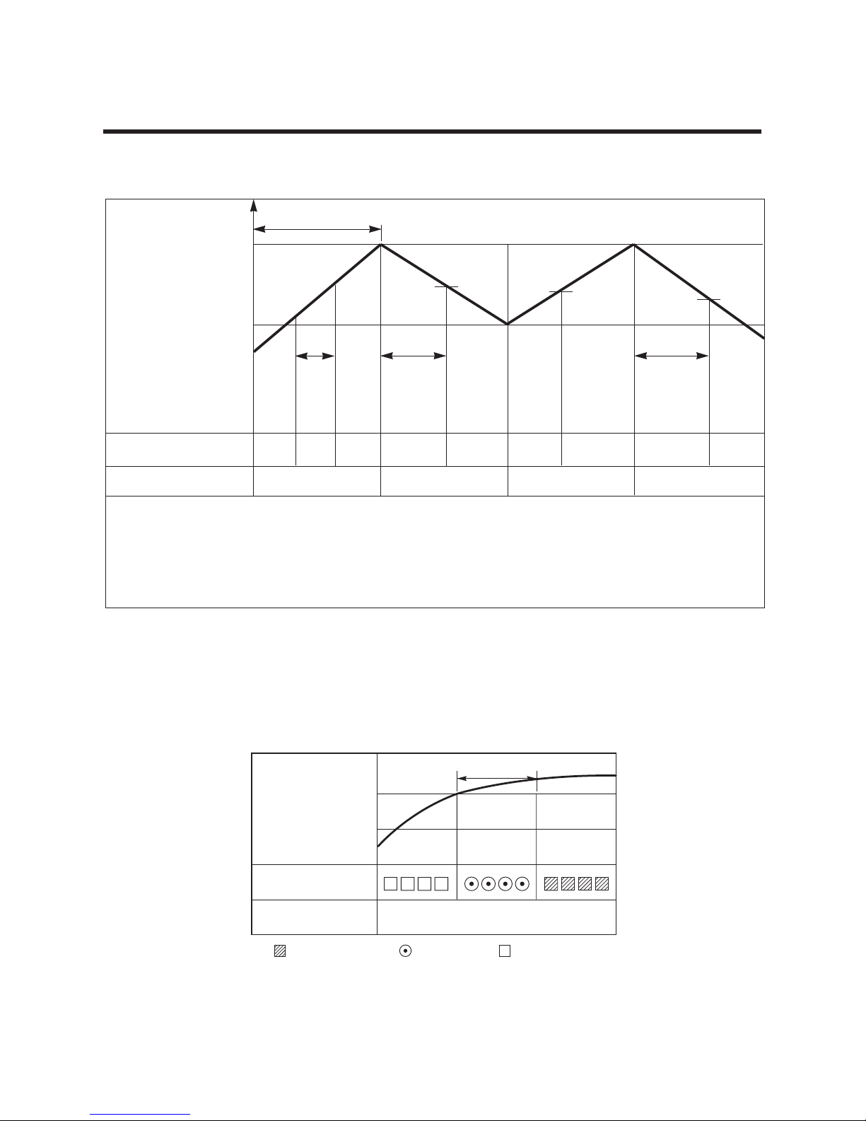
3. Cooling Mode Operation
• When selecting the Cooling( ) Mode Operation, the unit will operate according to remote controller settings and
the operation diagram is as following.
–10–
Intake Air temp.
SET TEMP.+0.5°C
(COMP. ON)
SET TEMP. -0.5°C
nahteroMnahteroM)FFO.PMOC(
setunim3setunim3
gnitceleSgnitceleSgnitceleS
deepsnafdeepsnafdeepsnaf
COMPRESSOR ON OFF ON OFF ON
INDOOR FAN Low Low
–11–
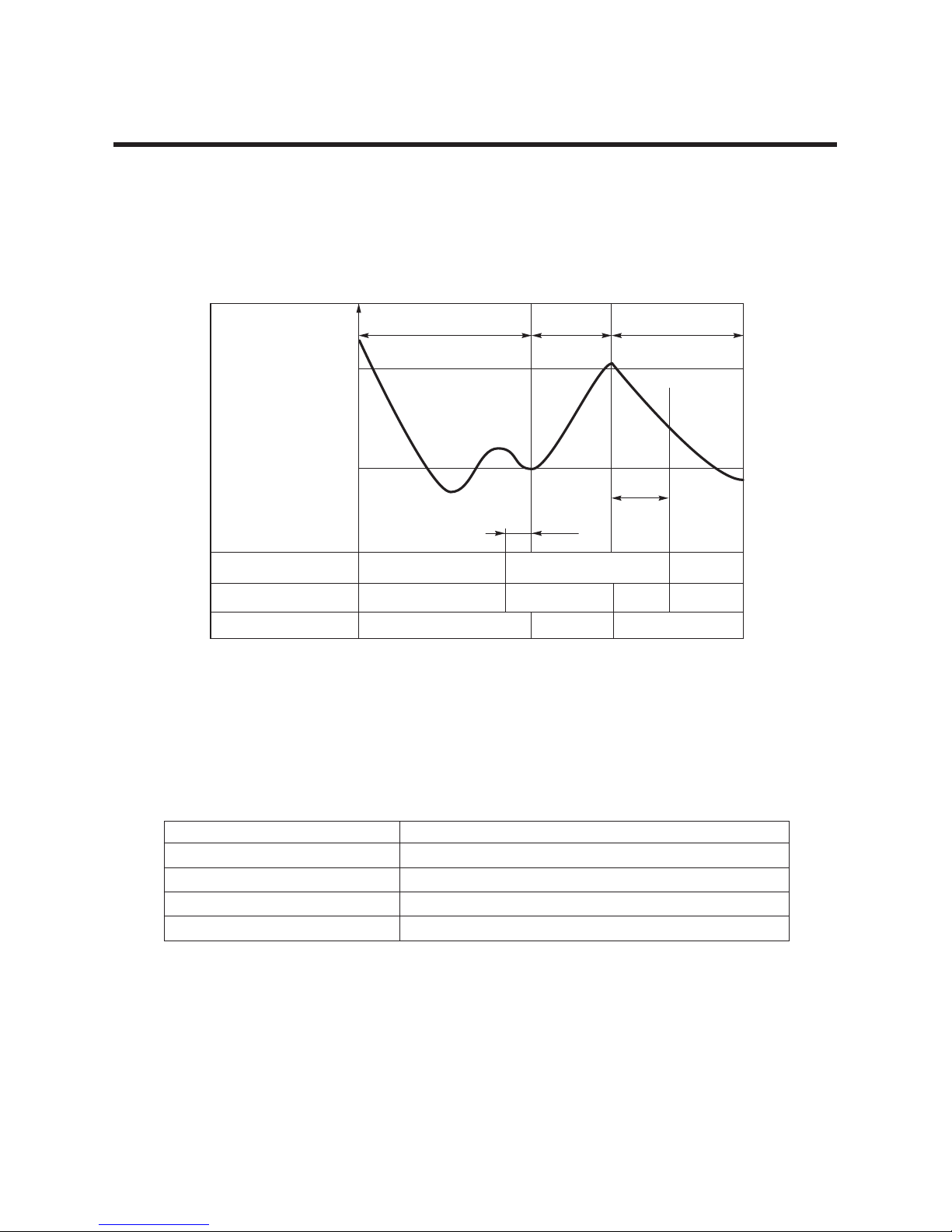
Intake Air temp.
Setting temp.+3°C
(Compressor OFF)
Setting temp.
(Compressor ON)
FFOwoLwoLFFOwoLNAFROODNI
COMPRESSOR ON OFF ON OFF
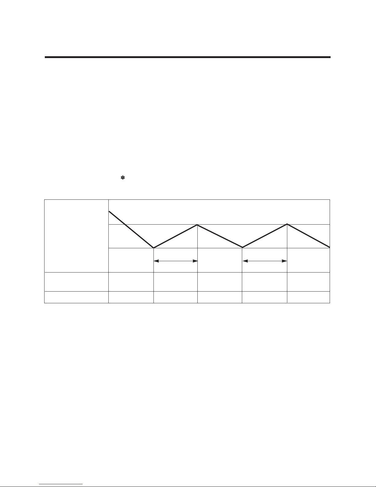
• A point; While the Indoor Heat-Exchanger temperature is higher than 40°C, the fan operates at low speed,
and when it becomes lower than 40ÛC fan stops.
• B point; When the Indoor Heat-Exchanger temperature is higher than 42°C, fan operates at seleted fan
speed, when it becomes lower than 39°C, the fan operates at low speed.
4. Heating Mode Operation (Except Cooling Model)
The unit will operate according to the remote controller settings and the operation diagram is shown as following.
Hot Start
Low
Selecting
Fan Speed
minimum 3min
Selecting fan
speed
minimum
10sec.
1min
AA
minimum
10sec.
B
5. Hot-Start Control
• The indoor fan stops until the evaporator piping temperature reaches to 31°C.
• The operation diagram is as following.
PIPING
TEMPERATURE
1min
COMPRESSOR
INDOOR FAN
ON
28°C
: Selected Fan : Low Fan : Fan Stop
31°C
–12–
6. Defrost Control
• Defrost control is available for 45 minutes since heating mode operation is started, and it will not prolong over
10 minutes.
• Defrost control is carried out when the outdoor pipe temp. falls below -6°C for more than 3 minutes after 45
minutes are passed from starting of heating operation.
• Defrost ends after 10 minutes are passed from starting of defrost operation or when the outdoor pipe temp.
rises to 12°C after 5 minutes are passed from starting of defrost.
7. Self-diagnosis Function
• 'CHECK' : Please contact your dealer if the remote controller displays this message 'CHECK'.
• Rectify the problem as shown in the table below before restarting operation.
• During the normal operation 'CHECK' won't be displayed in the remote controller.
Remote controller LCD Accident Point
CH 01 Indoor room temperature thermistor error
CH 02 Indoor piping thermistor error
CH 03
Indoor main body / Remote controller unit communication error
CH 04(Optional) Water level float switch error
More than 45 minutes
of heating operation
Within
9min. 45sec.
ON OFF
NONO
ON
ON OFF
OFF
COMPRESSOR
4-WAY VALVE
INDOOR FAN
-6°C ON
12°C OFF
The outdoor
piping Temp.
ON
More than 10 min.
running of compressor
More than 45 minutes
of heating operation
5sec.
HOT-
START
ON
–13–
Installation of Indoor, Outdoor Unit
1. Selection of the best location
1) Indoor unit
Select location
Install the air conditioner in the location that satisfies the following conditions.
• Place should easily bear a load exceeding four
times the indoor unit’s weight.
• The place should enable the unit to be inspected
as shown in fig.
• The place should be such that leveled.
• The place should allow easy water drainage.(Suit-
able dimension “H” is necessary to get a slope to
drain as figure.)
• The place should easily connect with the outdoor
unit.
• The place where the unit is not affected by an
electrical noise.
• The place where air circulation in the room will be
good .
• There should not be near the unit any heat source
or steam.
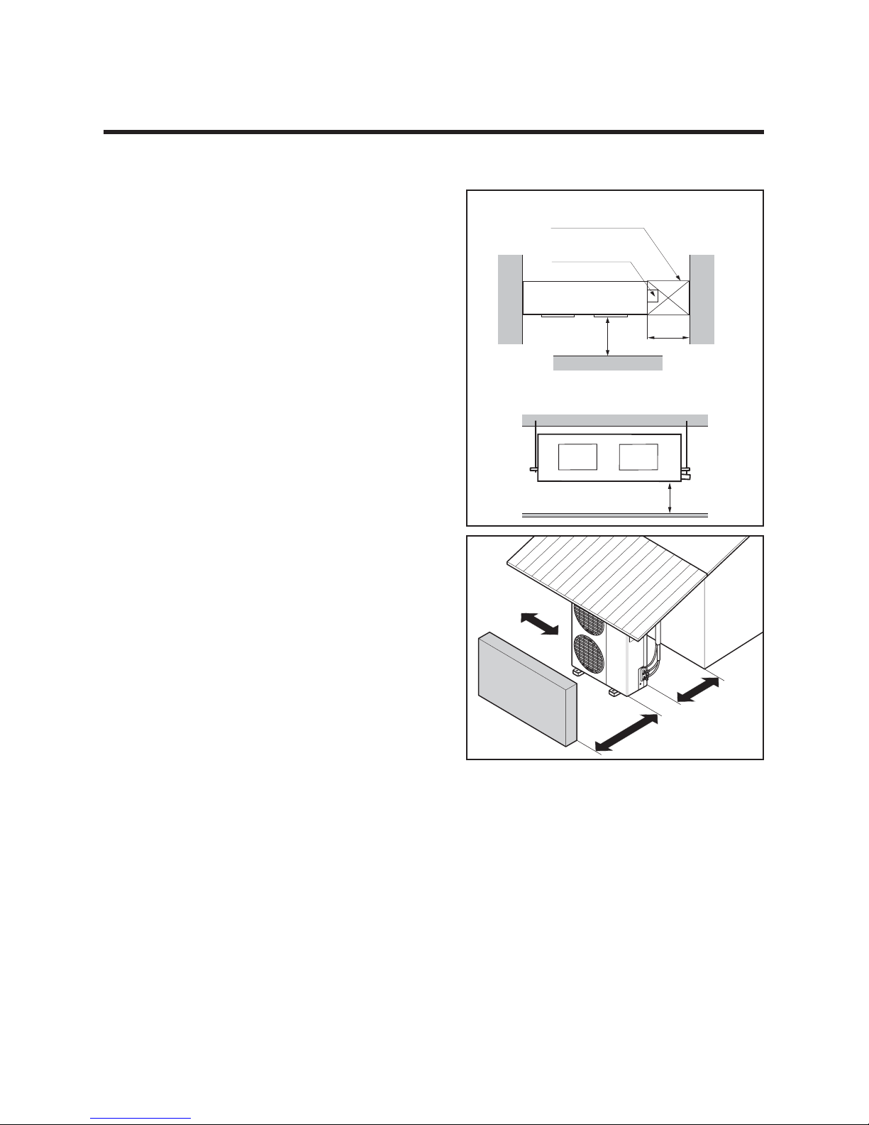
2) Outdoor unit
• If an awning is built over the unit to prevent direct
sunlight or rain exposure, be careful that heat
transfer from the condenser is not restricted.
• There should be no animals or plants in vicinity of
the hot discharged air.
• Ensure the space indicated by arrows from the
wall, ceiling, fence or other obstacles.
More than
30cm
More than
30cm
More than
70cm
Sunroof
Fence or
obstacles
Top view
(unit: mm)
H
Front view
450
Front
Inspection hole
(450X450)
Control box
0001
 Loading...