

lg HT303PD-D0, SH33PD-F, SH33PD-S, SH33PD-W Service Manual
MODEL: HT303PD(HT303PD-D0, SH33PD-F/S/W)
SERVICE MANUAL
DVD/CD RECEIVER
SERVICE MANUAL
MODEL: HT303PD
(HT303PD-D0, SH33PD-F/S/W)
Website http://biz.lgservice.com
Internal Use Only
P/NO : AFN73178958 JUNE, 2009

1-1
[CONTENTS]
❍ SECTION 1. GENERAL
• SERVICING PRECAUTIONS . . . . . . . . . . . . . . . . . . . . . . . . . . . . . . . . . . . . . . . . . . . . . . 1-2
• ESD PRECAUTIONS . . . . . . . . . . . . . . . . . . . . . . . . . . . . . . . . . . . . . . . . . . . . . . . . . . . . 1-4
• SERVICE INFORMATION FOR EEPROM . . . . . . . . . . . . . . . . . . . . . . . . . . . . . . . . . . . . . 1-5
•
HOW TO UPDATE AUDIO MICOM & DVD PROGRAMS
. . . . . . . . . . . . . . . . . . . . . . . . . . . . . . . . . . . . . 1-7
• SPECIFICATIONS . . . . . . . . . . . . . . . . . . . . . . . . . . . . . . . . . . . . . . . . . . . . . . . . . . . . . . 1-8
❍ SECTION 2. ELECTRICAL PART
• TROUBLESHOOTING GUIDE . . . . . . . . . . . . . . . . . . . . . . . . . . . . . . . . . . . . . . . . . . . . . 2-1
• DETAILS AND WAVEFORMS ON SYSTEM TEST AND DEBUGGING . . . . . . . . . . . . . . .2-13
• INTERNAL BLOCK DIAGRAM OF ICs . . . . . . . . . . . . . . . . . . . . . . . . . . . . . . . . . . . . . . .2-25
• WIRING DIAGRAM . . . . . . . . . . . . . . . . . . . . . . . . . . . . . . . . . . . . . . . . . . . . . . . . . . . . . 2-45
• OVERALL BLOCK DIAGRAM . . . . . . . . . . . . . . . . . . . . . . . . . . . . . . . . . . . . . . . . . . . . 2-47
• CIRCUIT DIAGRAMS . . . . . . . . . . . . . . . . . . . . . . . . . . . . . . . . . . . . . . . . . . . . . . . . . . . 2-49
• PRINTED CIRCUIT DIARGAMS . . . . . . . . . . . . . . . . . . . . . . . . . . . . . . . . . . . . . . . . . . . 2-69
❍ SECTION 3. EXPLODED VIEWS . . . . . . . . . . . . . . . . . . . . . . . . . . . . . . . . . . . . . . . . . 3-1
• CABINET AND MAIN FRAME SECTION . . . . . . . . . . . . . . . . . . . . . . . . . . . . . . . . . . . . . 3-1
• DECK MECHANISM EXPLODED VIEW(DP-12TV) . . . . . . . . . . . . . . . . . . . . . . . . . . . . . . 3-3
• PACKING ACCESSORY SECTION . . . . . . . . . . . . . . . . . . . . . . . . . . . . . . . . . . . . . . . . . . 3-5
• SPEAKER SECTION . . . . . . . . . . . . . . . . . . . . . . . . . . . . . . . . . . . . . . . . . . . . . . . . . . . . 3-6
❍ SECTION 4. MECHANISM (DP-12TV) . . . . . . . . . . . . . . . . . . . . . . . . . . . . . . . . . . . . 4-1
❍ SECTION 5. REPLACEMENT PARTS LIST . . . . . . . . . . . . . . . . . . . . . . . . . . . . . . . . 5-1
Copyright © 2009 LG Electronics. Inc. All right reserved.
Only for training and service purposes
LGE Internal Use Only
1-2
SERVICING PRECAUTIONS
NOTES REGARDING HANDLING OF THE PICK-UP
1. Notes for transport and storage
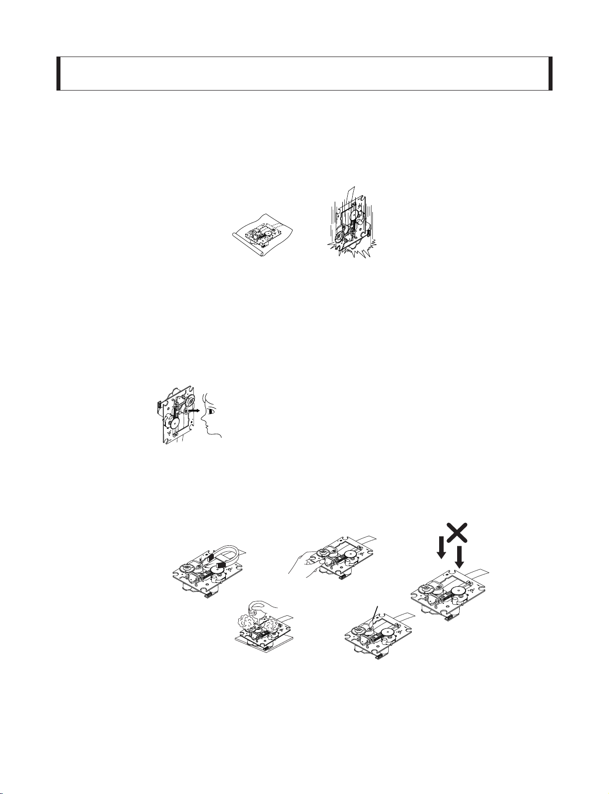
1) The pick-up should always be left in its conductive bag until immediately prior to use.
2) The pick-up should never be subjected to external pressure or impact.
2. Repair notes
1) The pick-up incorporates a strong magnet, and so should never be brought close to magnetic materials.
2) The pick-up should always be handled correctly and carefully, taking care to avoid external pressure and
impact. If it is subjected to strong pressure or impact, the result may be an operational malfunction and/or
damage to the printed-circuit board.
3) Each and every pick-up is already individually adjusted to a high degree of precision, and for that reason
the adjustment point and installation screws should absolutely never be touched.
4) Laser beams may damage the eyes!
Absolutely never permit laser beams to enter the eyes!
Also NEVER switch ON the power to the laser output part (lens, etc.) of the pick-up if it is damaged.
5) Cleaning the lens surface
If there is dust on the lens surface, the dust should be cleaned away by using an air bush (such as used
for camera lens). The lens is held by a delicate spring. When cleaning the lens surface, therefore, a cotton
swab should be used, taking care not to distort lens.
6) Never attempt to disassemble the pick-up.
Spring has excess pressure. If the lens is extremely dirty, apply isopropyl alcohol to the cotton swab.
(Do not use any other liquid cleaners, because they will damage the lens.) Take care not to use too much
of this alcohol on the swab, and do not allow the alcohol to get inside the pick-up.
Storage in conductive bag
Drop impact
NEVER look directly at the laser beam, and don’t allow
contact with fingers or other exposed skin.
Magnet
How to hold the pick-up
Conductive Sheet
Cotton swab
Pressure
Pressure
SECTION 1. GENERAL
Copyright © 2009 LG Electronics. Inc. All right reserved.
Only for training and service purposes
LGE Internal Use Only
1-3
NOTES REGARDING COMPACT DISC PLAYER REPAIRS
1. Preparations
1) Compact disc players incorporate a great many ICs as well as the pick-up (laser diode). These components
are sensitive to, and easily affected by, static electricity. If such static electricity is high voltage, components
can be damaged, and for that reason components should be handled with care.
2) The pick-up is composed of many optical components and other high-precision components. Care must be
taken, therefore, to avoid repair or storage where the temperature or humidity is high, where strong magnetism is present, or where there is excessive dust.
2. Notes for repair
1) Before replacing a component part, first disconnect the power supply lead wire from the unit
2) All equipment, measuring instruments and tools must be grounded.
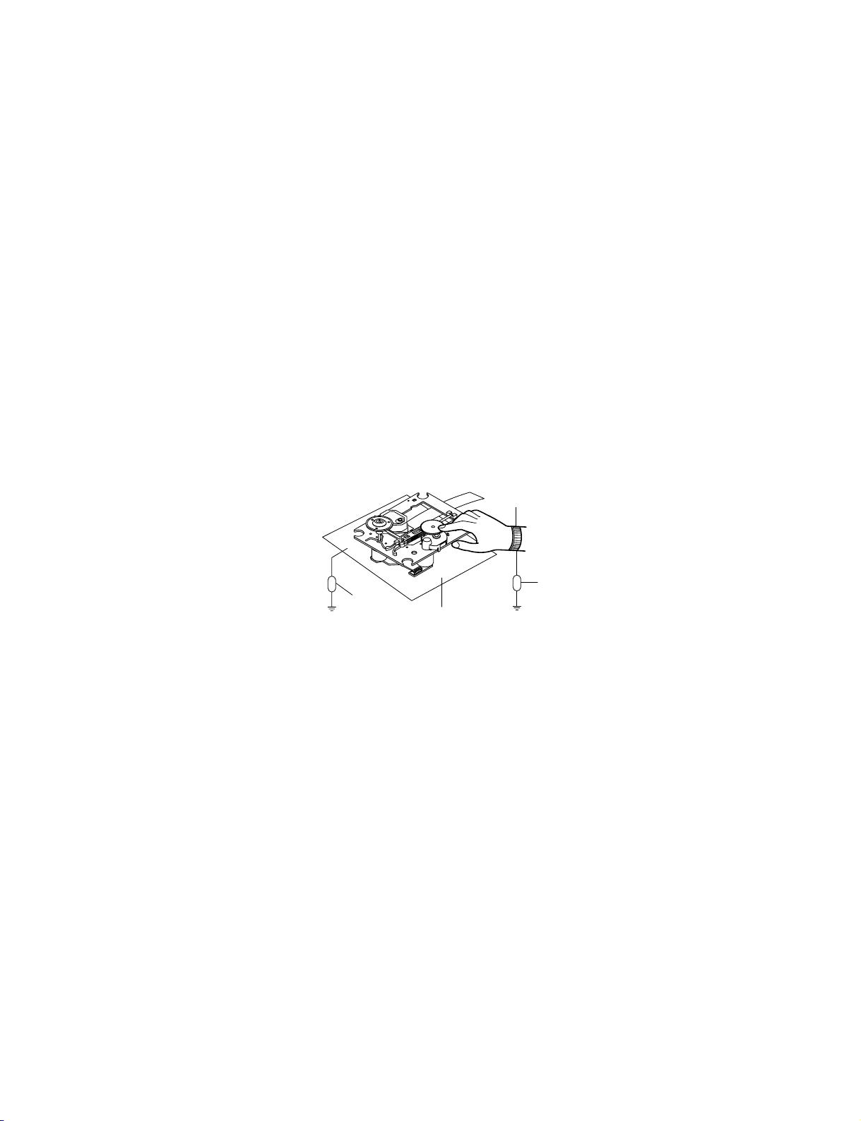
3) The workbench should be covered with a conductive sheet and grounded.
When removing the laser pick-up from its conductive bag, do not place the pick-up on the bag. (This is
because there is the possibility of damage by static electricity.)
4) To prevent AC leakage, the metal part of the soldering iron should be grounded.
5) Workers should be grounded by an armband (1M Ω)
6) Care should be taken not to permit the laser pick-up to come in contact with clothing, in order to prevent static electricity changes in the clothing to escape from the armband.
7) The laser beam from the pick-up should NEVER be directly facing the eyes or bare skin.
Resistor
(1 Mohm)
Conductive
Sheet
Resistor
(1 Mohm)
Armband
Copyright © 2009 LG Electronics. Inc. All right reserved.
Only for training and service purposes
LGE Internal Use Only
1-4
ESD PRECAUTIONS
Electrostatically Sensitive Devices (ESD)
Some semiconductor (solid state) devices can be damaged easily by static electricity. Such components
commonly are called Electrostatically Sensitive Devices (ESD). Examples of typical ESD devices are integrated
circuits and some field-effect transistors and semiconductor chip components. The following techniques should
be used to help reduce the incidence of component damage caused by static electricity.
1. Immediately before handling any semiconductor component or semiconductor-equipped assembly, drain off
any electrostatic charge on your body by touching a known earth ground. Alternatively, obtain and wear a
commercially available discharging wrist strap device, which should be removed for potential shock reasons
prior to applying power to the unit under test.
2. After removing an electrical assembly equipped with ESD devices, place the assembly on a conductive surface
such as aluminum foil, to prevent electrostatic charge buildup or exposure of the assembly.
3. Use only a grounded-tip soldering iron to solder or unsolder ESD devices.
4. Use only an anti-static solder removal device. Some solder removal devices not classified as "anti-static" can
generate electrical charges sufficient to damage ESD devices.
5. Do not use freon-propelled chemicals. These can generate electrical charges sufficient to damage ESD
devices.
6. Do not remove a replacement ESD device from its protective package until immediately before you are
ready to install it. (Most replacement ESD devices are packaged with leads electrically shorted together by
conductive foam, aluminum foil or comparable conductive materials).
7. Immediately before removing the protective material from the leads of a replacement ESD device, touch the
protective material to the chassis or circuit assembly into which the device will by installed.
CAUTION : BE SURE NO POWER IS APPLIED TO THE CHASSIS OR CIRCUIT, AND OBSERVE ALL OTHER
SAFETY PRECAUTIONS.
8. Minimize bodily motions when handing unpackaged replacement ESD devices. (Otherwise harmless motion
such as the brushing together of your clothes fabric or the lifting of your foot from a carpeted floor can generate static electricity sufficient to damage an ESD device).
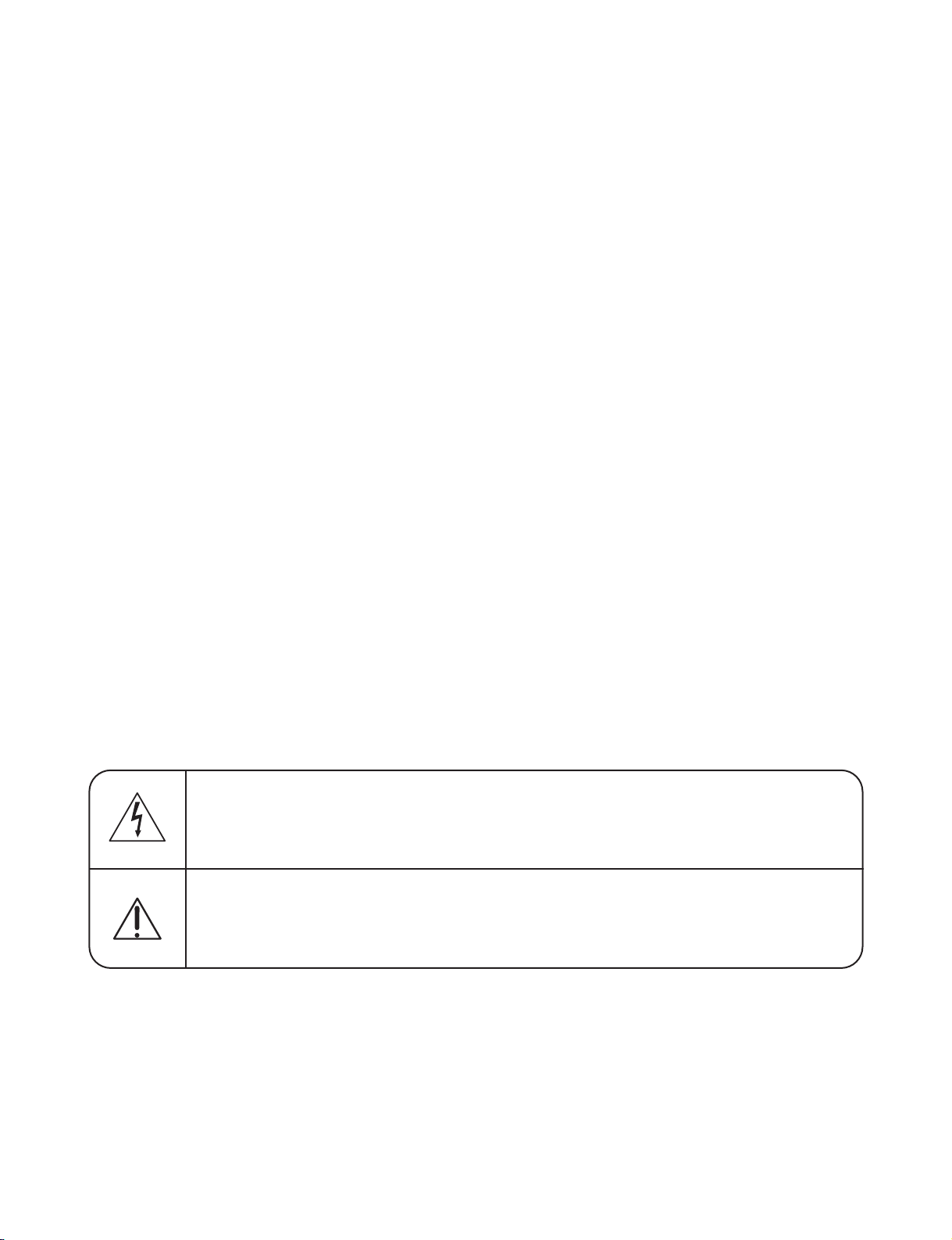
CAUTION. GRAPHIC SYMBOLS
THE LIGHTNING FLASH WITH APROWHEAD SYMBOL. WITHIN AN EQUILATERAL TRIANGLE, IS
INTENDED TO ALERT THE SERVICE PERSONNEL TO THE PRESENCE OF UNINSULATED
“DANGEROUS VOLTAGE” THAT MAY BE OF SUFFICIENT MAGNITUDE TO CONSTITUTE A RISK OF
ELECTRIC SHOCK.
THE EXCLAMATION POINT WITHIN AN EQUILATERAL TRIANGLE IS INTENDED TO ALERT THE
SERVICE PERSONNEL TO THE PRESENCE OF IMPORTANT SAFETY INFORMATION IN SERVICE
LITERATURE.
Copyright © 2009 LG Electronics. Inc. All right reserved.
Only for training and service purposes
LGE Internal Use Only
1-5
Copyright © 2009 LG Electronics. Inc. All right reserved.
Only for training and service purposes
LGE Internal Use Only
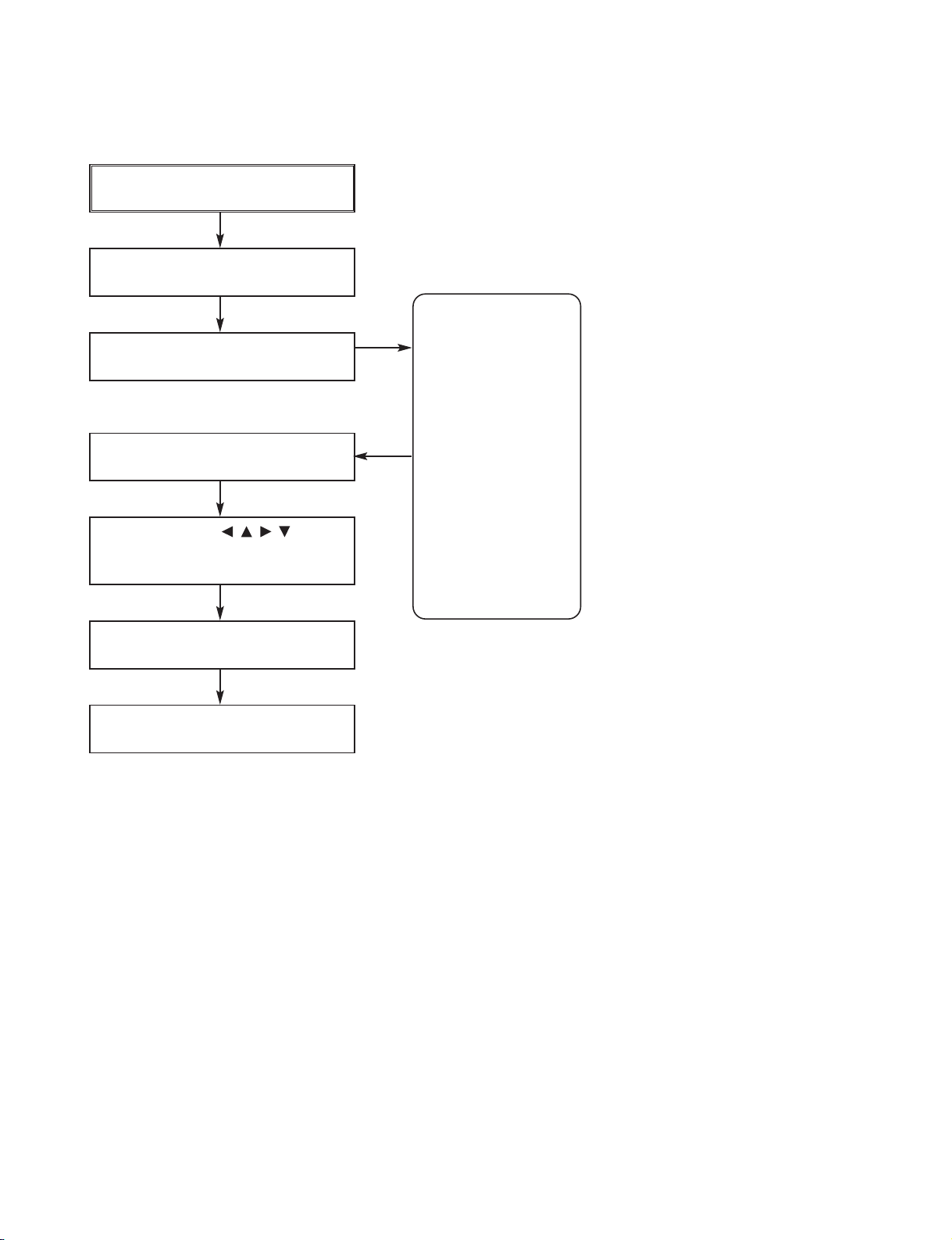
SERVICE INFORMATION FOR EEPROM (DVD PART)
POWER ON
DVD LOGO Status (NO Disk status)
Remote control
Pause key-->1-->4-->7-->2 in order.
Press number 0~9, Press character
A~F (1~6 for a while)
Use arrow key ( ) to
move to appropriate position and
make changes
Press pause key once
Change will be applied when power
OFF-->ON.
DETECT NEW EEPROM
(OPTION EDIT SCREEN)
HEX
53
45
20
FD
22
05
EC
32
AC
00
00
00
00
00
00
00
NAME
OPT 1
OPT 2
OPT 3
OPT 4
OPT 5
OPT 6
OPT 7
OPT 8
OPT 9
OPT A
OPT B
OPT C
OPT D
OPT E
OPT F
OPT G

1-6
SERVICE INFORMATION FOR EEPROM (MICOM PART)
POWER ON
FLD no disc status
Remote control ‘2’ + Front ‘STOP’
push same timing during 5s
FLD ‘OP-0….
Use arrow key ( ) move
to appropriate position and make
changes
Press ENTER key once
FLD ‘write ok’ or ‘up ok’
Remote control ‘2’ + Front ‘STOP’
push same timing
FLD display E2P CLR or EP CLR
Auto power off
NAME HEX
OPT 1 82
OPT 2 CA
OPT 3 22
OPT 4 27
OPT 5 00
DETECT NEW EEPROM
(OPTION EDIT SCREEN)
Copyright © 2009 LG Electronics. Inc. All right reserved.
Only for training and service purposes
LGE Internal Use Only

1-7
HOW TO UPDATE AUDIO MICOM & DVD PROGRAMS
1. How to update AUDIO MICOM program.
[Update using CD]
1. Change the filename to download as “(MODEL NAME)_(Version).HEX”. Only upper cases are permitted.
ex) HT303PD : “HT303PD_0709081.HEX”
2. Copy the file to the root folder of a CD and burn it.
3. Insert the CD to the SET, and move to the DVD function. Then the upgrade process will be started with
the upgrade information.
4. If the upgrade process is complete, the set will be rebooted with “Complete” message.
[Update using USB]
1. Change the filename to download as “(MODEL NAME)_(Version).HEX”. Only upper cases are permitted.
ex) HT303PD : “HT303PD_0709081.HEX”
2. Copy the file to the root folder of USB storage.
3. Put the USB into the SET, and move to the USB function. Then the upgrade process will be started with
the upgrade information.
4. If the upgrade process is complete, the set will be rebooted with “Complete” message.
2. How to update DVD program.
[Update using CD]
1. Rename the filename to download as “TARGET.BIN” in upper cases.
2. Copy the file to “\MTK_UPG\” folder of CD, and burn it.
ex) P:\MTK_UPG\TARGET.BIN
3. Insert the CD to the SET, then after a while the CD tray will be opened with upgrade information on the
screen.
4. Remove the CD, and press UP key in remote controller.
5. Remove and reconnect the power cable when it changes to logo screen from upgrade information.
Then the upgrade process is completed.
[Update using USB]
1. Rename the filename to download as “TARGET.BIN” in upper cases.
2. Copy the file to “\MTK_UPG\” folder of the formatted USB, and burn it.
ex) P:\MTK_UPG\TARGET.BIN
3. Move to the USB function, and insert the USB to the set. The upgrade information will be shown on the
screen.
4. Remove the USB, press UP key of the remote control.
5. Remove and reconnect the power cable when it changes to logo screen from upgrade information.
Then the upgrade process is completed.
Copyright © 2009 LG Electronics. Inc. All right reserved.
Only for training and service purposes
LGE Internal Use Only

1-8
SPECIFICATIONS
GENERAL
Power supply Refer to main label
Power consumption Refer to main label
Net Weight 2.5 kg
External dimensions (W x H x D) 360 x 62 x 305 mm
Operating conditions Temperature: 5°C to 35°C, Operation status: Horizontal
Operating humidity 5% to 85%
AMPLIFIER
Output Power Front: 45 W + 45 W (Rated Output Power 30 W, THD 10 %)
Centre*: 45 W
Surround*: 45 W + 45 W (Rated Output Power 30 W, 4 Ωat 1 kHz, THD 10 %)
Subwoofer*: 75 W (Rated Output Power 60 W, 8 Ωat 30 Hz, THD 10 %)
SPEAKERS
Front Speaker Center/Rear Speaker Passive Subwoofer
SH33PD-F SH33PD-S SH33PD-W
Impedance 4 Ω 4 Ω 8 Ω
Net Dimensions 260 x 1100 x 260 mm 99 x 114 x 86 mm 156 x 325 x 320 mm
(W x H x D)
Net Weight (1EA) 3.0 kg 0.37 kg 3.5 kg
Designs and specifications are subject to change without notice.
(* Depending on the sound mode
settings and the source, there may
be no sound output.)
Copyright © 2009 LG Electronics. Inc. All right reserved.
Only for training and service purposes
LGE Internal Use Only
2-1
SECTION 2. ELECTRICAL PART
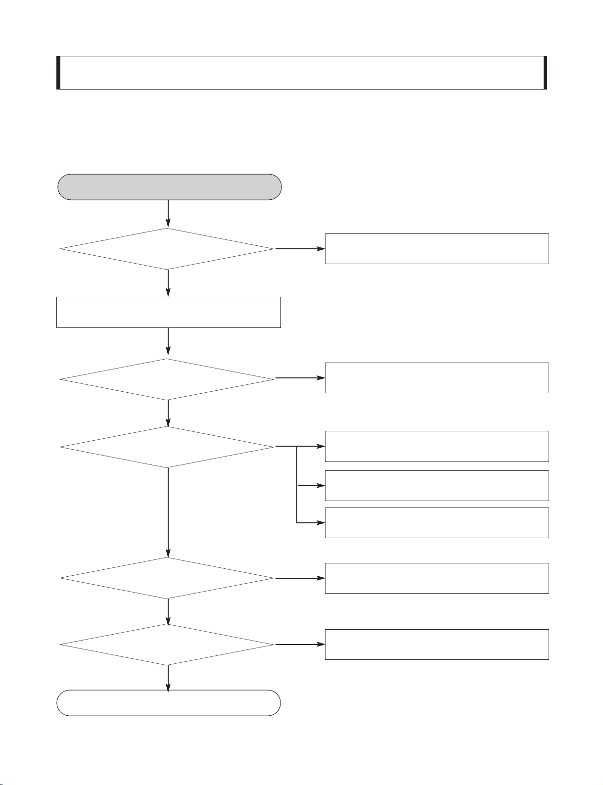
TROUBLESHOOTING GUIDE
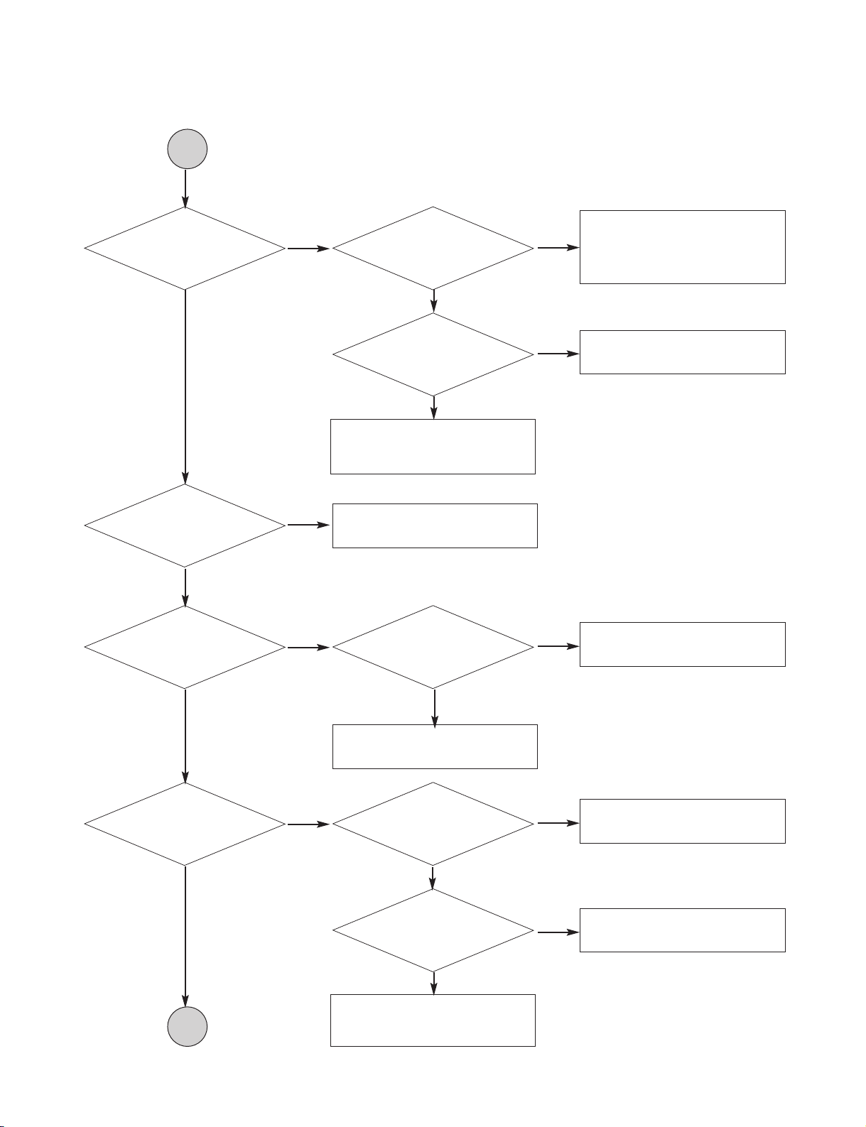
1. Power Supply Circuit
YES
NO
Check power plug and power
supply circuit.
NO
Check power supply circuit.
NO
Check laser circuit.
Check focus circuit.
Check disc.
NO
Check tracking servo circuit.
NO
Check audio circuit.
Does red power led
turn on?
YES
Is power on?
YES
Does red power led
turn on?
YES
Does it play?
YES
Does it output
audio?
YES
YES
Turn power on.
INSERT POWER CORD.
OK
Copyright © 2009 LG Electronics. Inc. All right reserved.
Only for training and service purposes
LGE Internal Use Only
2-2
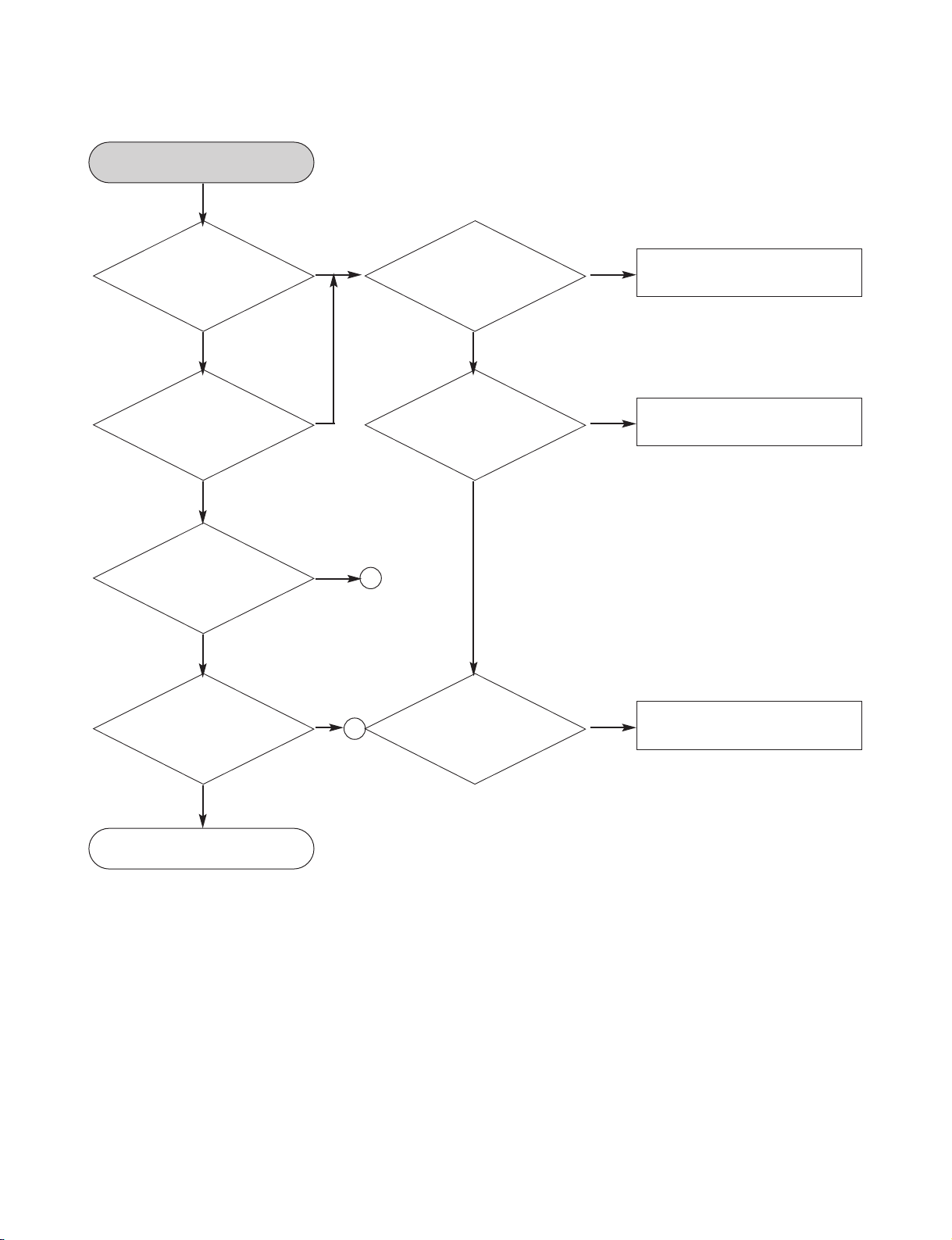
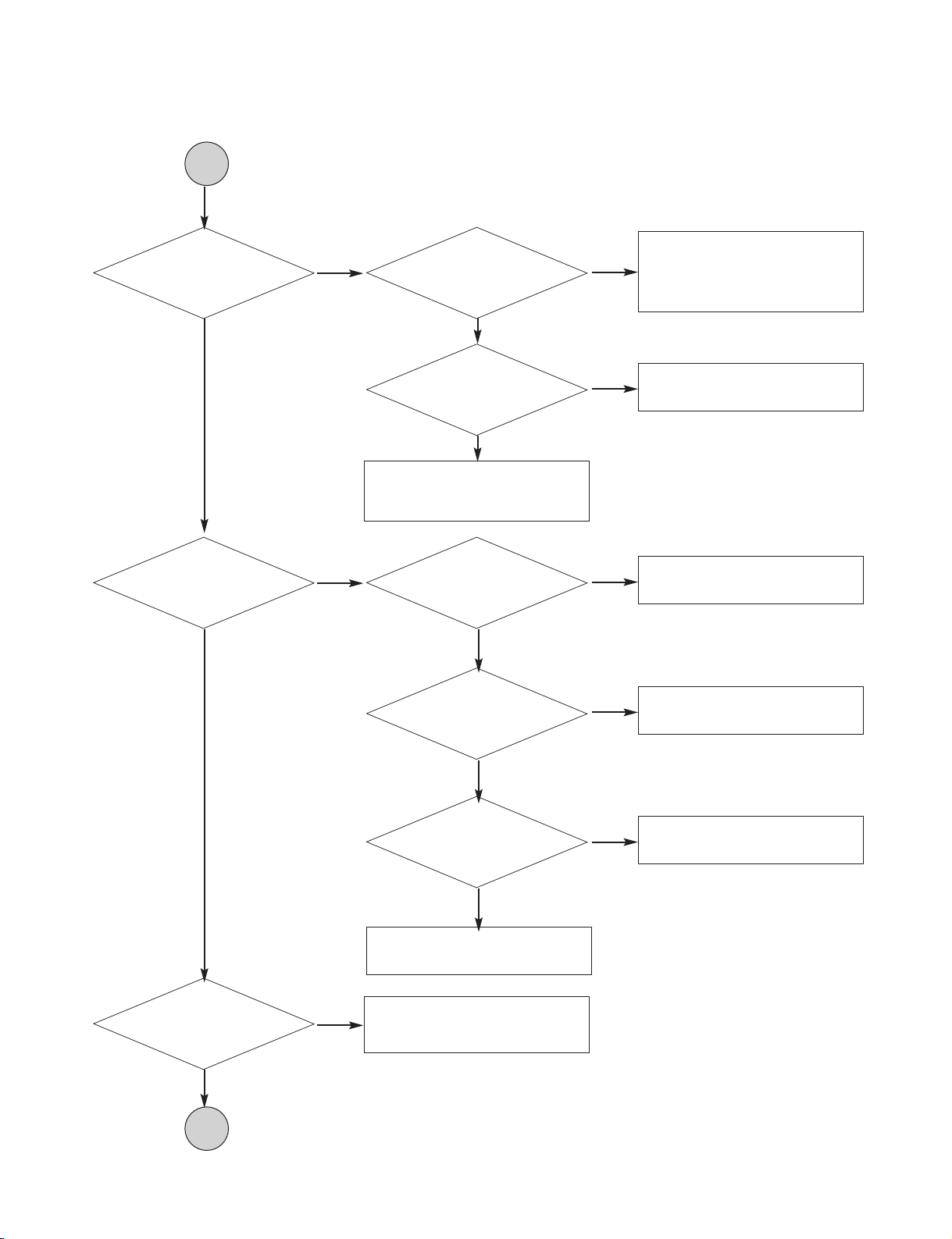
2. Front circuit (1/2)
NO NO
Reconnect it.
YES
YES YES
Check if
PN103 is ok?
Red LED turn off?
NO
NO
Refer to SMPS part.
YES
YES
Check if the front
power is ok?
Is the Digitron on
correctly?
NO NO
Check pattern and resoldering
YES
Check if
RC2 is ok?
Check if the remote
control is ok?
YES
Check if all
buttons are ok?
POWER ON.
Front B/D ok.
1
2
Copyright © 2009 LG Electronics. Inc. All right reserved.
Only for training and service purposes
LGE Internal Use Only
2-3
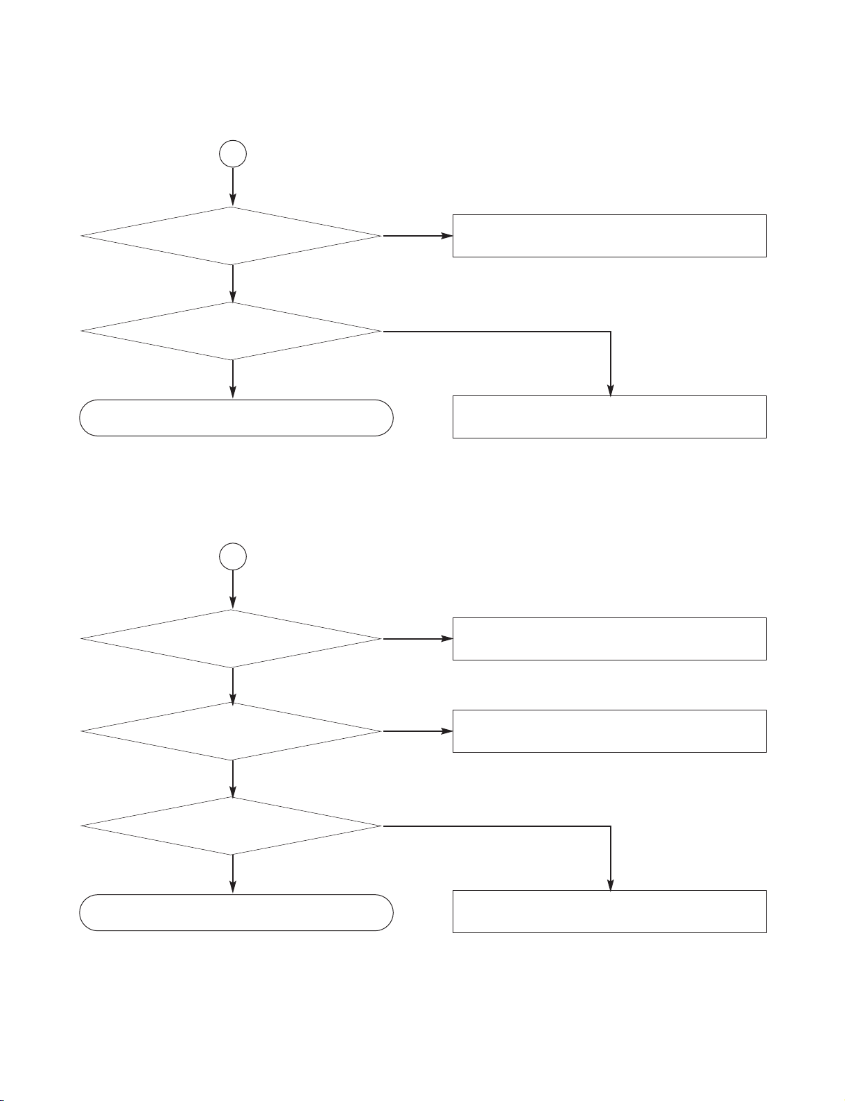
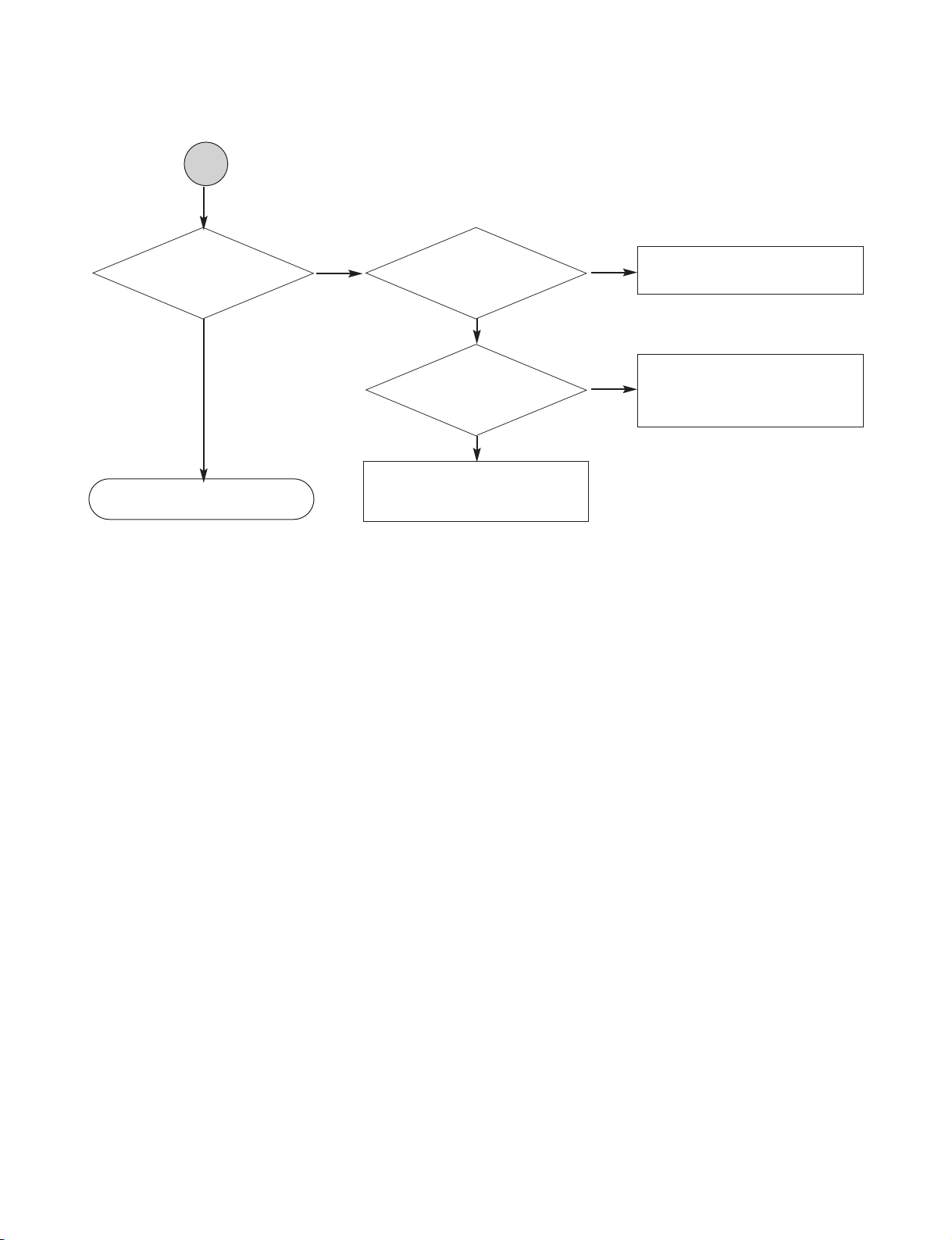
3. Front circuit (2/2)
1
NO
Refer to power(SMPS).
NO
Replace R345 ~ R350.
Check if the
power part of the
front is ok?
YES
Check if
R345~R350
ok?
YES
Refer to MICOM circuit.
2
NO
Refer to power(SMPS).
NO
Check RM circuit
Check if the power
part of the front is ok?
YES
NO
Refer to MICOM circuit.
Check if the remote
control waveform of PN301
pin5 is ok?
YES
Check if RC2
voltage is ok(5V)?
YES
Resolder or Replace RC2.
Copyright © 2009 LG Electronics. Inc. All right reserved.
Only for training and service purposes
LGE Internal Use Only
2-4
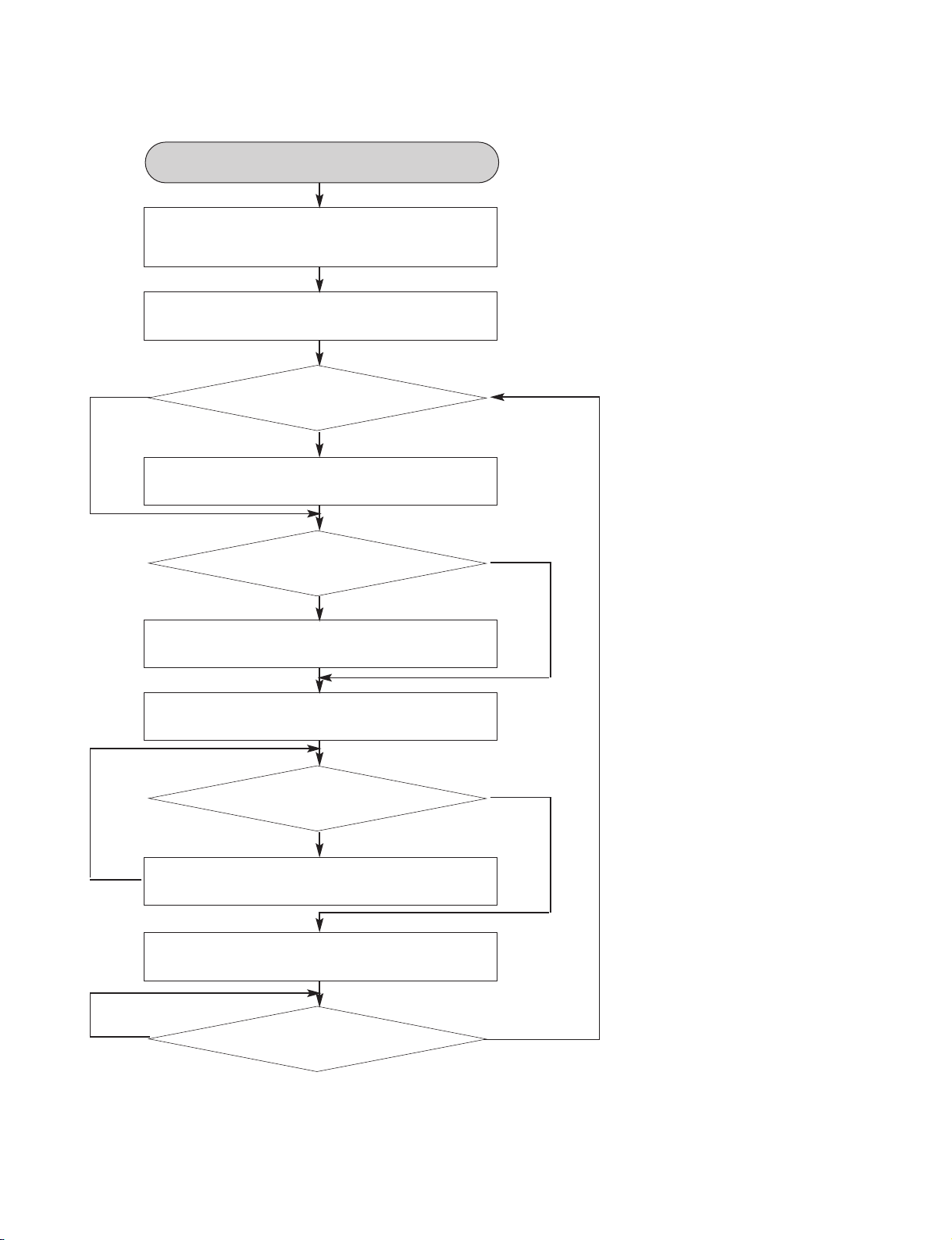
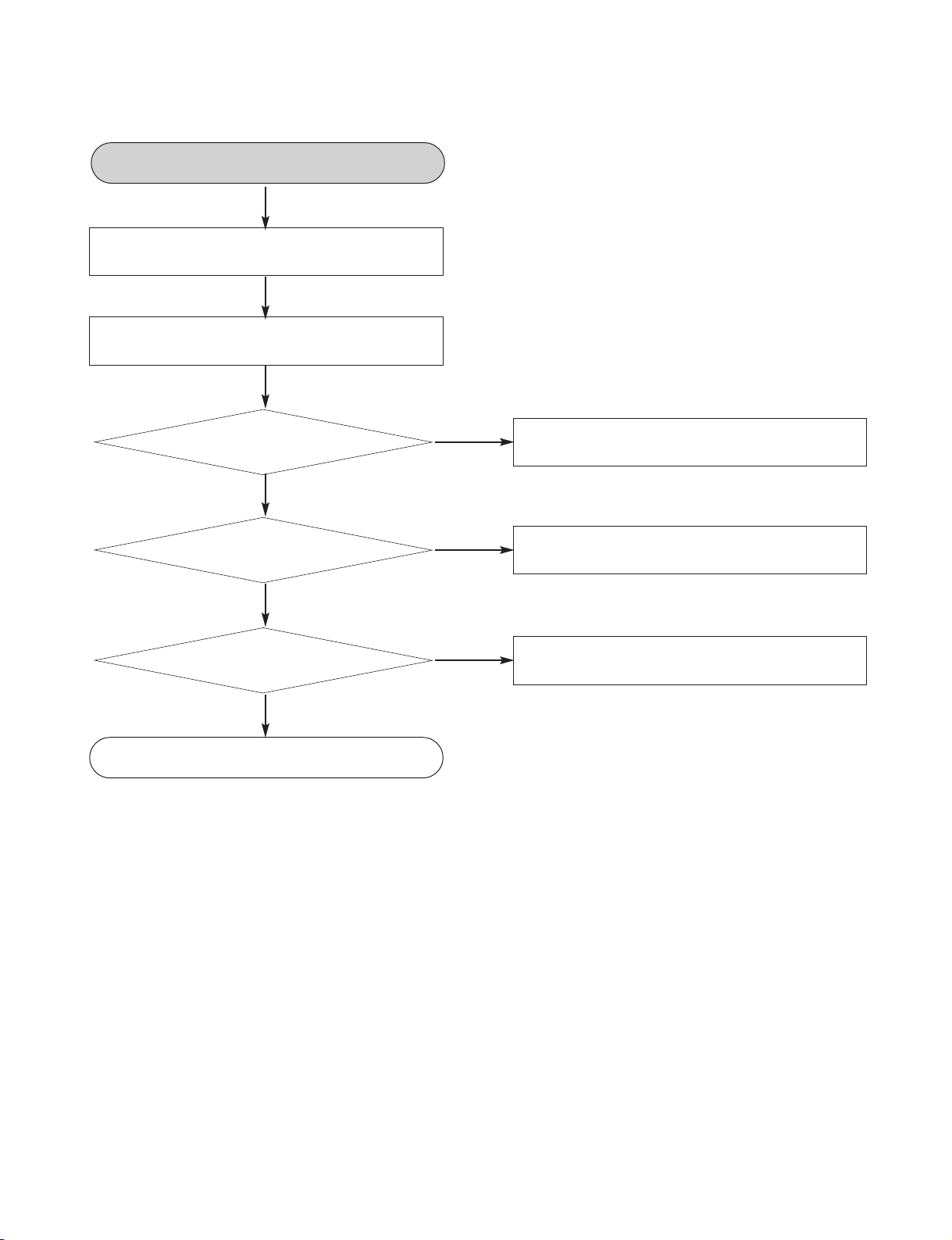
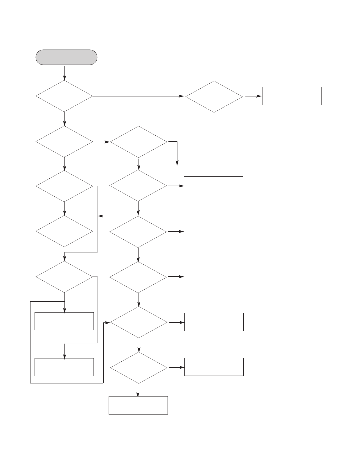
4. System operation flow
YES
YES
YES
Tray closed?
1. Initializes SERVO, DSP & RISC registers.
2. Write RISC code to SDRAM.
3. Reset RISC.
Show LOGO.
Tray close to closed position.
SLED at inner
side?
Recieve
OPEN/ CLOSE
Key?
Receive
CLOSE Key?
SLED moves to inner position.
1. Judge whether have disc and disc type.
2. Jump to related disc reading procedure.
1. Execute Pressed Key & IR Key.
2. System operation routine loop.
NO
NO
NO
NO
YES
1. Stop Playback & Open Tray.
2. Display tray open message & LOGO.
POWER ON.
Copyright © 2009 LG Electronics. Inc. All right reserved.
Only for training and service purposes
LGE Internal Use Only
2-5
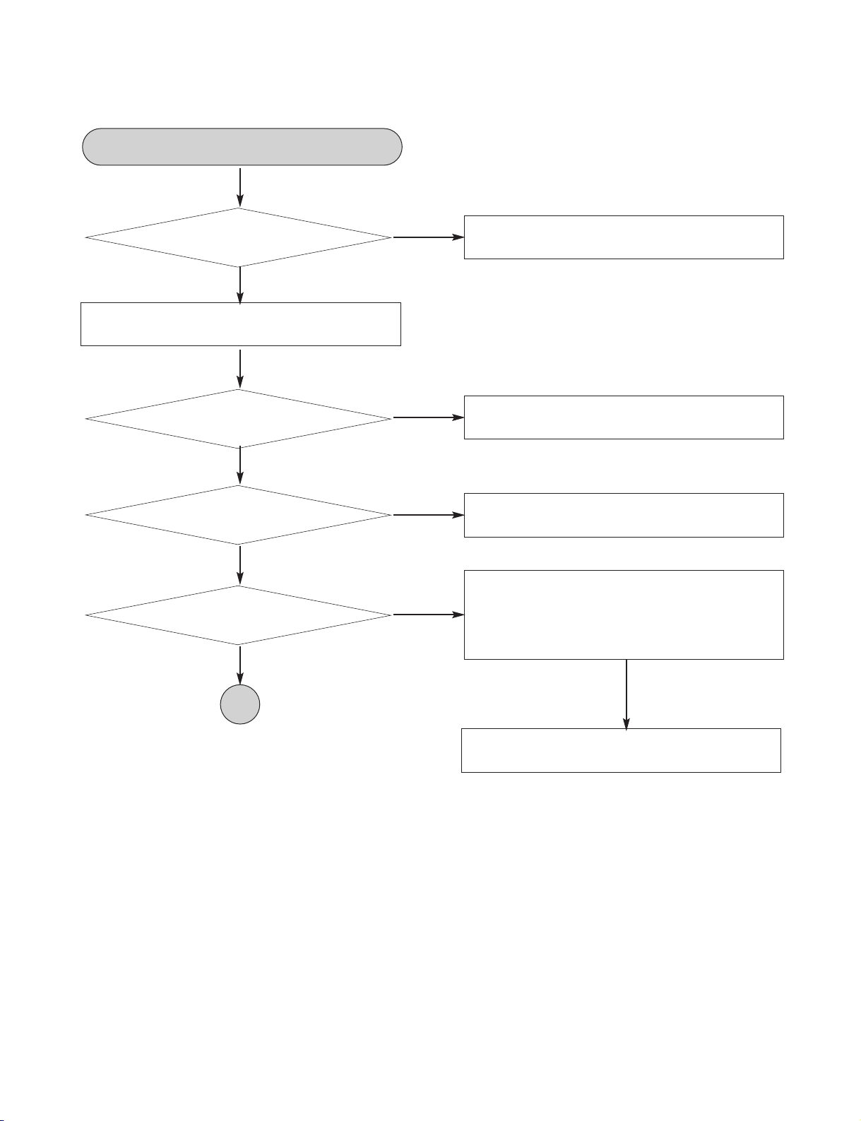
5. Test & debug flow
YES
NO
Check the POWER PART.
NO
Check the POWER PART.
Check the
AC voltage Power PCBA (110V
or 220V).
YES
NO
Check the regulators or diode.
NO
1. Check 27MHz system clock.
2. Check system reset circuit.
3. Check FLASH R/W enable signal PRD,
RWR.
4. Check FLASH Memory related circuit.
NO
Replace FLASH.
Are the
DC Voltage outputs OK? (12V, 5.6V,
3.5V, 5V,7V, 34V).
YES
Are 3.5V and
5V DC outputs normal on main
PCBA?
YES
YES
Update
FLASH successfully?
YES
Switch on the Power PCBA.
TEST.
A
Copyright © 2009 LG Electronics. Inc. All right reserved.
Only for training and service purposes
LGE Internal Use Only
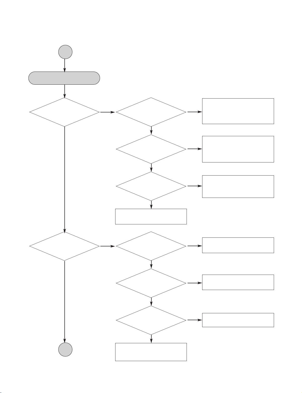
2-6
NO
NO
Check connection lines
between FLASH &MT1389/L
and the FLASH access time
whether is suitable or not.
YES
YES
YES
YES
Check AV cable
connection to TV set.
YES
YES
YES
Flash
Memory operates
properly?
NO
Check connection lines
between SDRAM(IC504) &
MT1389/L and the SDRAM
is damaged.
SDRAM
works properly?
NO
Check the related circuit of
MT1389/L IC501 Pins99, 102,
103, 104.
MT1389/L
VIDEO outputs
properly?
Show LOGO?
NO
NO
Check the load OPEN &
CLOSE switch.
Check AV cable connection
between main PCBA and
loader. (MECHA)
YES
YES
YES
Normal
OPEN_SW,
CLOSE_SW
signal?
NO
Check the Tray control IO pins
on MT1389/L.
Normal
TROPEN & TRCLOSE
signal?
NO
Check the Tray control MOTOR
& SERVO circuit IC401.
Normal
LOAD+ & LOAD-signal?
Does
Tray move inside when it
is not at closed
position?
Power On.
A
B
Copyright © 2009 LG Electronics. Inc. All right reserved.
Only for training and service purposes
LGE Internal Use Only
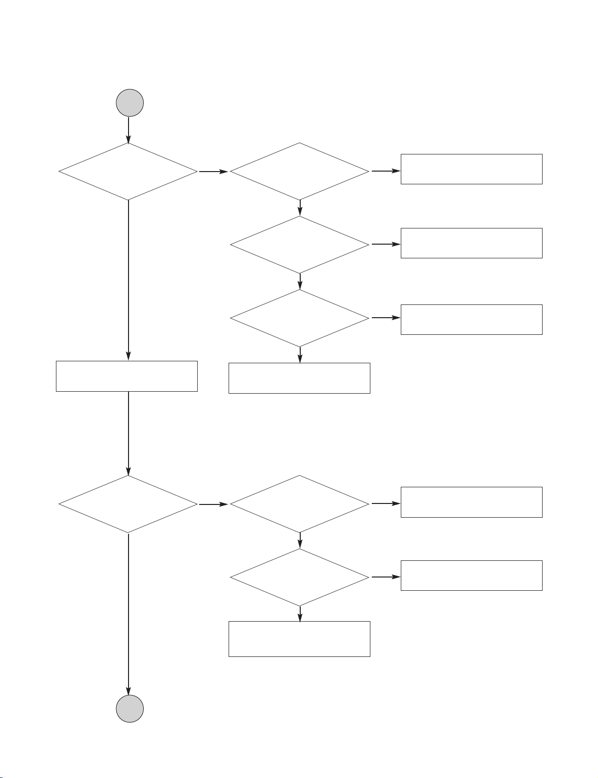
2-7
NO
NO
Check the connection line of
DRV_MUTE.
YES
YES
YES
Check the cable connection
with MECHA.
Do not put in disc
and close tray.
YES
YES
YES
Motor
Driver DRV_MUTE
pin is high?
NO
Check the related circuit of
SLEGN.
Motor
Driver DRV_MUTE
pin is High?
NO
Check the amp circuit on
motor driver.
SLED+ and
SLED- output
properly?
Does
the SLED move to inner
side when it is at outer
position?
NO
NO
Check Focus connection on
MT1389/L and motor driver.
Check cable connection with
pick-up head.
YES
YES
Proper Focus outputs
to motor dricer?
NO
Check the amp circuit on motor
driver.
Proper F+ & F- outputs?
Optical Lens
has movements for
searching Focus?
B
C
Copyright © 2009 LG Electronics. Inc. All right reserved.
Only for training and service purposes
LGE Internal Use Only
2-8
NO
NO
NO
Check the laser power circuit
on MT1389/L and connecting
to power transistor.
(Q401, Q402).
YES
YES
YES
YES
YES
YES
Check cable connection
between transistor output and
pick-up head.
Laser off.
Check the RF connection
between AM5890 and MT1389/L.
YES
YES
DVDLD or
CDLD output
property?
NO
Check the related circuit on
laser power transistor.
Collector
voltage of power transistor
is OK?(Q401, Q402)
Laser turns on when
reading disc?
Put disc in?
NO
NO
Check the SPINDLE related
circuit on MT1389/L.
Check the cable connection
between spindle and main
PCB.
YES
YES
Proper
SPINDLE signal on
MT1389/L.
NO
Check the spindle control amp
circuit of motor driver.
SPNP
SPNN output
properly?
Does spindle rotate?
NO
NO
Check the related circuit on
MT1389/L RF signal.
Proper
RF signal on MT1389/L.
Disc ID is correct?
C
D
Copyright © 2009 LG Electronics. Inc. All right reserved.
Only for training and service purposes
LGE Internal Use Only
2-9
NO
NO
Check connections between
MT1389/L and pick-up head.
YES
YES
YES
YES
YES
Check CD_DVDCT connection
between AM5890 and
MT1389/L.
Check cable connection
on pick-up head.
YES
YES
Proper
signals on A, B, C,
D of MT1389/L.
NO
Check the related circuit on
MT1389/L CD-DVDCT.
Proper
CD-DVDCT signal
on MT1389/L.
Focus on ok?
NO
Check RF signal waveform.
Disc Playback?
NO
NO
Check the related circuit on
MT1389/L.
NO
Check the TRACK connection
on MT1389/L and motor driver.
NO
Check the tracking control amp
circuit on motor driver.
Proper
CD-DVDCT signal
on MT1389/L.
YES
Proper
TRACK signal
on MT1389/L.
YES
TR+ & TR-output
properly?
Track On OK?
D
E
Copyright © 2009 LG Electronics. Inc. All right reserved.
Only for training and service purposes
LGE Internal Use Only
2-10
NO
NO
Check connection between
IC704 BCK, LRCK, ADATAO.
YES
YES
Check Digital Amp circuit
(IC702, IC703).
YES
YES
PWM IC
received correct data
stream?
NO
Check the related circuit of
PWM.(Check Audio out
Pins 55, 59, 61, 62, 68, 71, 75).
Normal
PWM IC out?(IC704).
Normal Audio
output when disc
playback?
E
TEST END.
Copyright © 2009 LG Electronics. Inc. All right reserved.
Only for training and service purposes
LGE Internal Use Only
2-11
6. AMP Protection
YES
NO
OK.
"PROTECTION"
appears continuously on the FLD.
YES
NO
Replace IC101.
Is the IC101 pin54
"LOW" signal(0V)?
YES
NO
Replace the Q701 and Q702.
Is the Q701 and Q702 normal?
YES
YES
After unplug power cord, connect again.
YES
Power on.
"PROTECTION" appears on the FLD.
Replace ST AMP IC(IC702 and IC703)
Copyright © 2009 LG Electronics. Inc. All right reserved.
Only for training and service purposes
LGE Internal Use Only
2-12
7. AUDIO µ-COM Circuit(DVD & AMP)
Check DVD Module.
Check SMPS.
OK
YES
Power On.
Does
CD/DVD appear at
FLD?
YES
NO
Does
Loading appear
at FLD?
Does
it appear DVD Error
at FLD?
Does Aux,
Scart, opt and FM 87.5
appear at FLD.
YES
Does
no Disc or Time
appear at FLD?
YES
Check
if DVD an audio
micom insert is
OK.
Check Power.
YES
YES
YES
Replace IC101.
YESNO
NO
NO
NO
Refer to SMPS.
NO
Refer to oscillator circuit.
NO
Check IC101 reset
waveform.
NO
NO
YES
Check
power part of Main
B/D.
Check
oscillator of
X101.
Check
if IC101 Pin5
is high.
YES
YES
YES
Check 3.3V line.
NO
Check power section
circuit.
NO
Check
if IC101 Pin9,36,59 are
high(5V).
Check
if IC101 Pin49
is high.
YES
YES
Copyright © 2009 LG Electronics. Inc. All right reserved.
Only for training and service purposes
LGE Internal Use Only
2-13
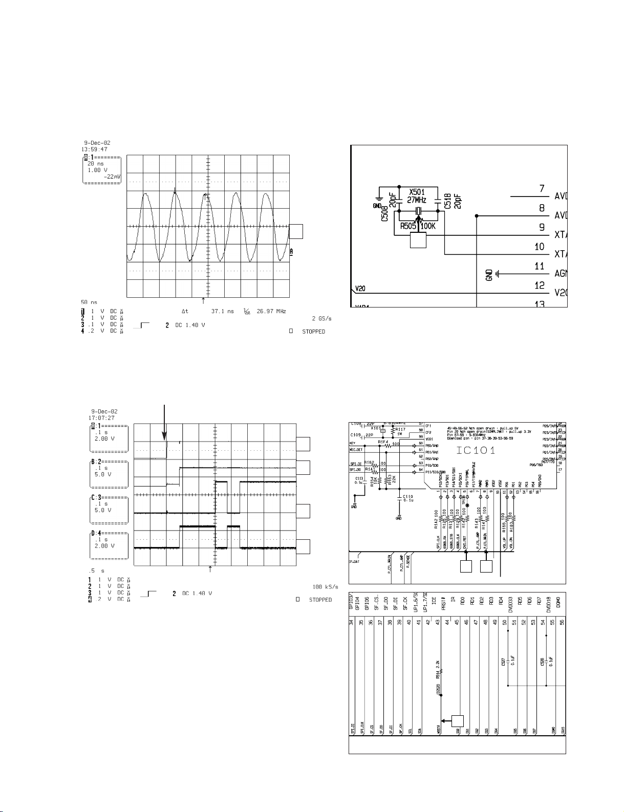
DETAILS AND WAVEFORMS ON SYSTEM TEST AND DEBUGGING
1. SYSTEM 27MHz CLOCK,RESET,FLASH R/W SIGNAL
1)
MT1389/L
main clock is at 27MHz(X501)
1
3 2
4
FIG 1-1
2)
MT1389/L
reset is high active.
Power Cord in
FIG 1-2
1
1
2
3
4
1
2
3
4
IC501
Copyright © 2009 LG Electronics. Inc. All right reserved.
Only for training and service purposes
LGE Internal Use Only
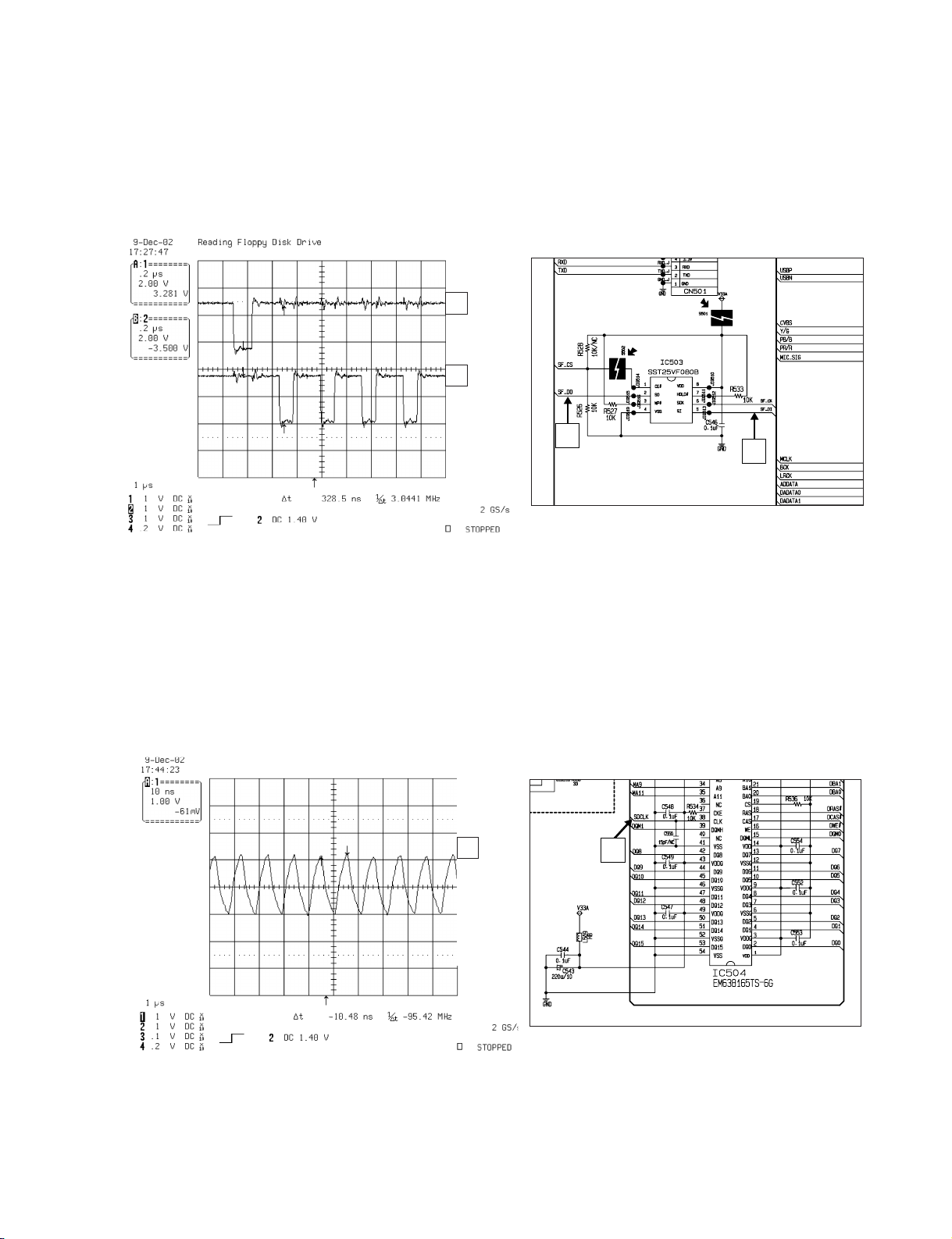
2-14
2. SDRAM CLOCK
1)
MT1389/L
main clock is at 27MHz(X501)
DCLK = 93MHz, Vp-p=2.2, Vmax=2.7V
FIG 2-1
3) Flash R/W enable signal during download(Downloading)
FIG 1-4
1
2
1
1
2
1
Copyright © 2009 LG Electronics. Inc. All right reserved.
Only for training and service purposes
LGE Internal Use Only
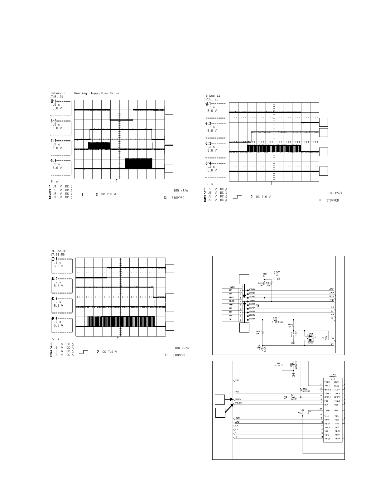
2-15
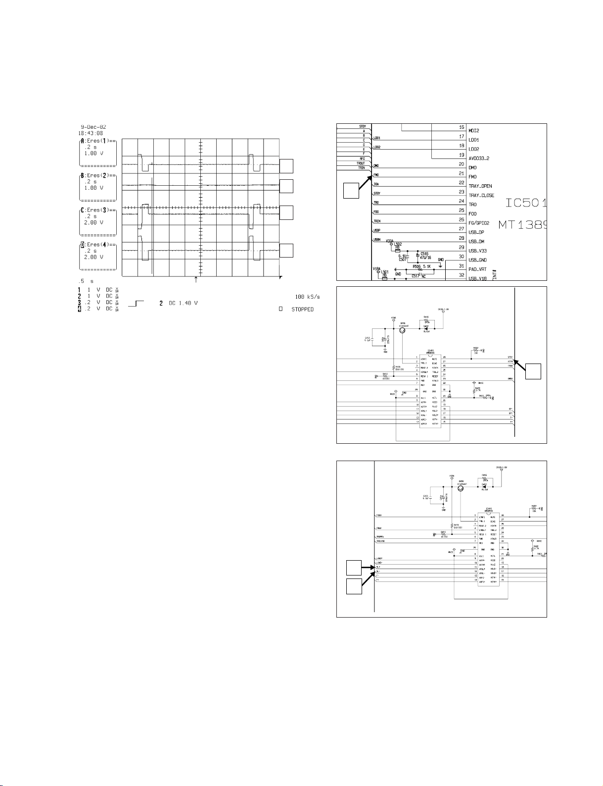
3) Tray open waveform
FIG 3-3
3. TRAY OPEN/CLOSE SIGNAL
1) Tray open/close waveform
FIG 3-1
2) Tray close waveform
FIG 3-2
2
1
3
4
1
2
3
4
1
2
3
4
1
2
3
4
Copyright © 2009 LG Electronics. Inc. All right reserved.
Only for training and service purposes
LGE Internal Use Only
2-16
4. SLED CONTROL RELATED SIGNAL (NO DISC CONDITION)
FIG 4-1
1
2
3
4
1
2
3
4
Copyright © 2009 LG Electronics. Inc. All right reserved.
Only for training and service purposes
LGE Internal Use Only
 Loading...