

Page 1

OWNER’S MANUAL
Video Conference System
Please read this manual carefully before operating
your set and retain it for future reference.
MODEL
RVF1000
P/NO : MFL66683302 1105 (V1.5)
Page 2
Safety Information
2
1
1
Safety Information
Safety Information
CAUTION
RISK OF ELECTRIC SHOCK
DO NOT OPEN
CAUTION: TO REDUCE THE RISK OF ELECTRIC SHOCK
DO NOT REMOVE COVER (OR BACK)
NO USER-SERVICEABLE PARTS INSIDE
REFER SERVICING TO QUALIFIED SERVICE PERSONNEL.
This lightning ash with arrowhead symbol
within an equilateral triangle is intended to
alert the user to the presence of uninsulated
dangerous voltage within the product’s
enclosure that may be of sucient magnitude
to constitute a risk of electric shock to persons.
The exclamation point within an equilateral
triangle is intended to alert the user to
the presence of important operating and
maintenance (servicing) instructions in the
literature accompanying the product.
This Class A digital apparatus complies with Canadian ICES-003.
Cet appareil numérique de la classe A est conforme à la norme
NMB-003 du Canada.
Warning: Do not install this equipment in a conned space such as
a bookcase or similar unit.
Warning: Wiring methods shall be in accordance with the National
Electric Code, ANSI/NFPA 70.
Warning: This is a class A product. In a domestic environment this
product may cause radio interference in which case the user may
be required to take adequate measures.
Warning: To reduce a risk of re or electric shock, do not expose
this product to rain or moisture.
Caution: This installation should be made by a qualied service
person and should conform to all local codes.
Caution: To avoid electrical shock, do not open the cabinet. Refer
servicing to qualied personnel only.
Caution: The apparatus should not be exposed to water (dripping
or splashing) and no objects lled with liquids, such as vases, should
be placed on the apparatus.
FCC WARNING: This equipment may generate or use radio
frequency energy. Changes or modications to this equipment may
cause harmful interference unless the modications are expressly
approved in the instruction manual. The user could lose the
authority to operate this equipment if an unauthorized change or
modication is made.
REGULATORY INFORMATION: FCC Part 15
This equipment has been tested and found to comply with the
limits for a Class A digital device, pursuant to Part 15 of the FCC
Rules. These limits are designed to provide reasonable protection
against harmful interference when the equipment is operated in a
commercial environment.
This equipment generates, uses, and can radiate radio frequency
energy and, if not installed and used in accordance with the
instruction manual, may cause harmful interference to radio
communications.
Operation of this equipment in a residential area is likely to cause
harmful interference in which case the user will be required to
correct the interference at his own expense.
• A suitable conduit entries, knock-outs or glands shall be
provided in the cable entries of this product in the end user.
• Caution: Danger of explosion if battery is incorrectly replaced.
Replaced only with the same or equivalent type recommended
by the manufacturer. Dispose of used batteries according to the
manufacturer’s instructions.
• Holes in metal, through which insulated wires pass, shall
have smooth well rounded surfaces or shall be provided with
brushings.
To disconnect power from mains, pull out the mains cord plug.
When installing the product, ensure that the plug is easily
accessible.
LG Electronics hereby declares that this/these
product(s) is/are in compliance with the essential
requirements and other relevant provisions of
Directive 2004/108/EC, 2006/95/EC, and 2009/125/
EC.
European representative :
LG Electronics Service Europe B.V. Veluwezoom 15,
1327
AE Almere. The Netherlands
(Tel : +31-(0)36-547-8888)
Page 3
Safety Information
3
Disposal of your old appliance
1. When this crossed-out wheeled bin symbol is
attached to a product it means the product is
covered by the European Directive 2002/96/EC.
2. All electrical and electronic products should
be disposed of separately from the municipal
waste stream via designated collection facilities
appointed by the government or the local
authorities.
3. The correct disposal of your old appliance will help
prevent potential negative consequences for the
environment and human health.
4. For more detailed information about disposal of
your old appliance, please contact your city oce,
waste disposal service or the shop where you
purchased the product.
• EEE Compliance with Directive. (for Turkey only)
• The equipment complies with requirements of the Technical
Regulation, in terms of restrictions for the use of certain
dangerous substances in electrical and electronic equipment.
(for Ukraine only)
Safety way to remove the battery or the battery from the
equipment:
Remove the old battery or battery pack, follow the steps in
reverse order than the assembly. To prevent contamination of the
environment and bring on possible threat to human and animal
health, the old battery or the battery put it in the appropriate
container at designated collection points. Do not dispose of
batteries or battery together with other waste. It is recommended
that you use local, free reimbursement systems batteries and
accumulators. The battery shall not be exposed to excessive heat
such as sunshine, re or the lile.
Disposal of waste batteries/accumulators
1. When this crossed-out wheeled bin symbol
is attached to batteries/accumulators of Your
product it means they are covered by European
Directive 2006/66/EC.
2. This symbol may be combined with chemical
symbols for mercury(Hg), cadmium(Cd) or
lead(Pb) if the battery Contains more that
0.0005% of mercury, 0.002% of cadmium or
0.004% of lead.
3. All batteries/accumulators should be disposed
separately from the municipal waste stream via
designated collection facilities appointed by the
government or the local authorities.
4. The correct disposal of Your old batteries/
accumulators will help to prevent potential
negative consequences for the environment,
animal and human health.
5. For more detailed information about disposal of
Your old batteries/accumulators, please contact
Your city oce, waste disposal service or the
shop where You purchased the product.
IMPORTANT SAFETY INSTRUCTIONS
1
Safety Information
1. Read these instructions.
2. Keep these instructions.
3. Heed all warnings.
4. Follow all instructions.
5. Do not use this apparatus near water.
6. Clean only with dry cloth.
7. Do not block any ventilation openings. Install in accordance
with the manufacturer’s instructions.
8. Do not install near any heat sources such as radiators, heat
registers, stoves, or other apparatus (including ampliers) that
produce heat.
9. Do not defeat the safety purpose of the polarized or groundingtype plug. A polarized plug has two blades with one wider
than the other. A grounding type plug has two blades and
a third grounding prong. The wide blade or the third prong
are provided for your safety. If the provided plug does not t
into your outlet, consult an electrician for replacement of the
obsolete outlet.
10. Protect the power cord from being walked on or pinched
particularly at plugs, convenience receptacles, and the point
where they exit from the apparatus.
11. Only use attachments/accessories specied by the
manufacturer.
12. Use only with the cart, stand, tripod, bracket, or table specied
by the manufacturer, or sold with the apparatus. When a
cart is used, use caution when moving the cart/apparatus
combination to avoid injury from tip-over.
13. Unplug this apparatus during lightning storms or when unused
for long periods of time.
14. Refer all servicing to qualied service personnel. Servicing is
required when the apparatus has been damaged in any way,
such as power-supply cord or plug is damaged, liquid has been
spilled or objects have fallen into the apparatus, the apparatus
has been exposed to rain or moisture, does not operate
normally, or has been dropped.
Page 4

Safety Information
4
Safety Warnings and Cautions
1
The following are warnings and cautions for the safety of the users and for the prevention of any property damage. Please read the following
Safety Information
carefully.
WARNING
• Turn o the system before installation. Do not plug in several electric devices to the same outlet.
- This may cause over heating, re, or electric shock.
• Do not place any liquid container on the system, such as water, coee, or other beverage.
- If liquid is poured into the system, it can cause a system breakdown or re.
• Prevent the power cable from being severely bent or having pressure exerted on it by a heavy object.
- This may cause re.
• Dust around the system on a regular basis. When cleaning the system, always use a dry cloth. Do not use a wet cloth or other organic
solvents.
- This may damage the surface of the system and can cause a system breakdown or electric shock.
• Avoid placing the system near moisture, dust, or soot.
- This can cause re or electric shock.
• When pulling the power cable from the plug, do so gently. Do not touch the plug with wet hands and avoid using the plug if the holes in
the outlet are too loose.
- This may cause re or electric shock.
• Do not attempt to disassemble, repair, or modify the system on your own. It is extremely dangerous due to the high voltage running
through the system.
- This may cause re, electric shock, or serious injury.
• Check for any danger signs such as a wet oor, a loosened or damaged power cable, or an unstable surface. If you encounter any problems,
ask your dealer for assistance.
- This may cause re or electric shock.
• Keep at least 15 cm between the back of the system and the wall for the cables connected to the system, otherwise they may be bent,
damaged, or cut.
- This may cause re, electric shock, or injury.
• Install the system in a cool place without direct sunlight and always maintain room temperature. Avoid candlelight and heat generating
devices such as heaters. Keep the system away from places where many people pass.
- This may cause re.
• Install the system on a plain surface with sucient air ventilation. Do not place the system on an elevated surface.
- This may cause system breakdown or serious injury.
• The power outlet must be placed on the ground, and the voltage range must be within 10 % of the voltage rate. Do not use the same
outlet with a hair dryer, iron, refrigerator, or any heating appliances.
- This may cause re, over heating or electric shock.
Page 5

Safety Information
CAUTION
Please beware of the following precautions before installing the VCS.
• Avoid positioning the product in any place where the unit may come into contact with moisture, dust, or soot.
• Avoid placing in direct sunlight or near heating appliances.
• Keep the product away from electric sparks or magnetic substances.
• Avoid temperature extremes. (Recommended operating temperature is between 0 °C and 40 °C)
• Do not place any conductive material through the ventilation grills.
• Keep the system turned o before installation.
• Ensure enough space is left for cable connections.
• Place the system on a solid surface with sucient air ventilation. Avoid any surface that vibrates.
• Placing the system near electronic devices such as a radio may cause the product to breakdown.
• Do not disassemble the product without seeking assistance from LG Electronics.
• Do not place any heavy object on the system.
• Prevent any substances from being inserted into the system.
- This may cause system breakdown.
• Install the system in a place with sucient air ventilation.
- Keep at least 15 cm between the back of the system and the wall.
• Do not install the system in a place with high magnetic, electric wave, or wireless devices such as a radio.
- Do not install the system in a place with magnetic objects, electric frequencies, or vibration.
• Do not place any heavy object on the system.
- This may cause system breakdown.
• Install the system on a stable, level surface.
- The system may not operate properly.
• Install the system in a place with appropriate moisture and temperature levels.
- Avoid installing the system in a place with high (over 40 °C) or low (under 0 °C) temperature.
• The system can be damaged from a strong impact or vibration. Avoid throwing objects within the vicinity of the system.
• Avoid direct sunlight or any heating appliances.
- Recommended operating temperature is over 0 °C (32 °F).
• Ventilate the air inside the system operation room, and tighten the system cover rmly.
- System breakdown may be caused by an inappropriate environment. It is recommended to use AVR (Automatic Voltage Regulator)
for a stable power supply. It is recommended to coil the core-ferrite around the connector of the system to avoid electromagnetic
interference.
• The outlet must be placed on the ground.
• If there is strange sound or smell, unplug the power cable immediately and contact the service center.
- This may cause re or electric shock.
• In order to maintain stable system performance, have your system checked regularly by the service center.
- LG Electronics is not held responsible for system breakdown caused by user mishandling.
- There is a risk of explosion if a battery is replaced by an incorrect type. Dispose of used batteries according to the instructions.
• Do not overturn the product during use.
5
1
Safety Information
Page 6

Contents
6
Contents
1
Safety Information
3 IMPORTANT SAFETY INSTRUCTIONS
4 Safety Warnings and Cautions
2
Preparation
8 Introduction
8 What is the VCS System?
8 Features
9 Unpacking
10 Codec Unit Overview
11 HD Camera Overview
12 Remote Control
12 Battery Installation
3
Installation
13 Connections
13 Precautions
13 Connection Overview
14 HDMI Connection
15 HD Camera Connection
16 PC Connection
17 Connecting to a Network
18 Connecting a Headphone
18 Connecting a Microphone
19 Connecting Power
19 System Connection Check
20 Initial Settings
23 Main Screen Overview
24 System Configuration Menu
25 User Settings
25 General
26 Audio
27 Video
28 Date Time
29 Admin Settings
29 Call Settings
33 Network Settings
37 System Settings
Page 7

38 System Information
38 System Status
38 Audio/Video
39 Network Utility
39 Server Status
4
Operation
40 Before Using the System
40 Placing a Call
40 Placing a Call Manually
41 Placing a Call from the Call History
41 Placing a Call from the Directory
42 Placing a Call using the Speed Dial
42 Answering or Rejecting a Call
42 Managing a Call
42 Ending a Call
42 Hiding or Showing User Interface Elements
42 Managing Audio
43 Managing Video Layout
43 Sharing Content
43 Viewing Call Information
44 Get the Snapshot
44 Managing the Directory
44 Adding an Entry to the Directory
45 Editing or Deleting an Entry from the Directory
46 Copying an Entry from the Call History
46 Copying an Entry from the Corporate Contact
46 Deleting an Entry from the Call History
47 Sorting and Searching
47 Placing a Call when the Device is Registered in Gatekeeper Server
47 Making a Call when the Device is Registered in SIP Server
47 Using Far End Camera Control
47 Using Far End Camera Preset
48 Using SnapShot
48 Using the Web Service
48 Upgrading your System Software
49 Uploading the Certification File
49 Importing or Exporting the Address Book
Contents
7
1
2
3
4
5
5
Appendix
50 Troubleshooting
52 Open Source Software Notice
53 Specifications
Page 8
Preparation
8
2
Preparation
2
Preparation
Introduction
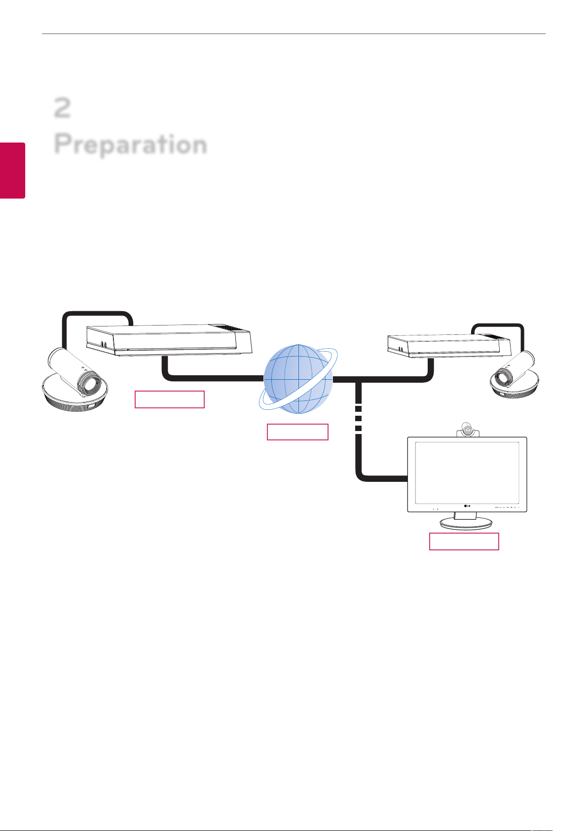
What is the VCS System?
The LG video conference system is designed to be used for video conferencing that enables people in dierent places to have a meeting by
seeing, listening and speaking to each other on a screen.
Through this device, not only can executives or managers have a meeting and communicate with customers, subcontractors and coworkers
in real time but decisions can be made and information can be exchanged virtually and immediately, saving travel time, cost and energy.
VCS
Network
Features
• Convenient and easy graphical user interface
• H.323 / SIP network Internation Standard codec
• HD video quality – 1 280 X 720 (30 fps)
• Editable screen layouts
• Graphic presentation using Content Sharing Technology (Share Document/Audio/Video)
• Administrator password and H235 codec (Advanced Encryption Standard) for security
• One-touch call connecting using speed dial
• Create graphical directory using snapshot and groups can be specied
• Easy phonebook search function
• 720p high-denition camera
• Natural sounding conversation using full duplex mode
• Built-in speaker
• Electret Condenser Microphone
VCS
Page 9
Preparation
Unpacking
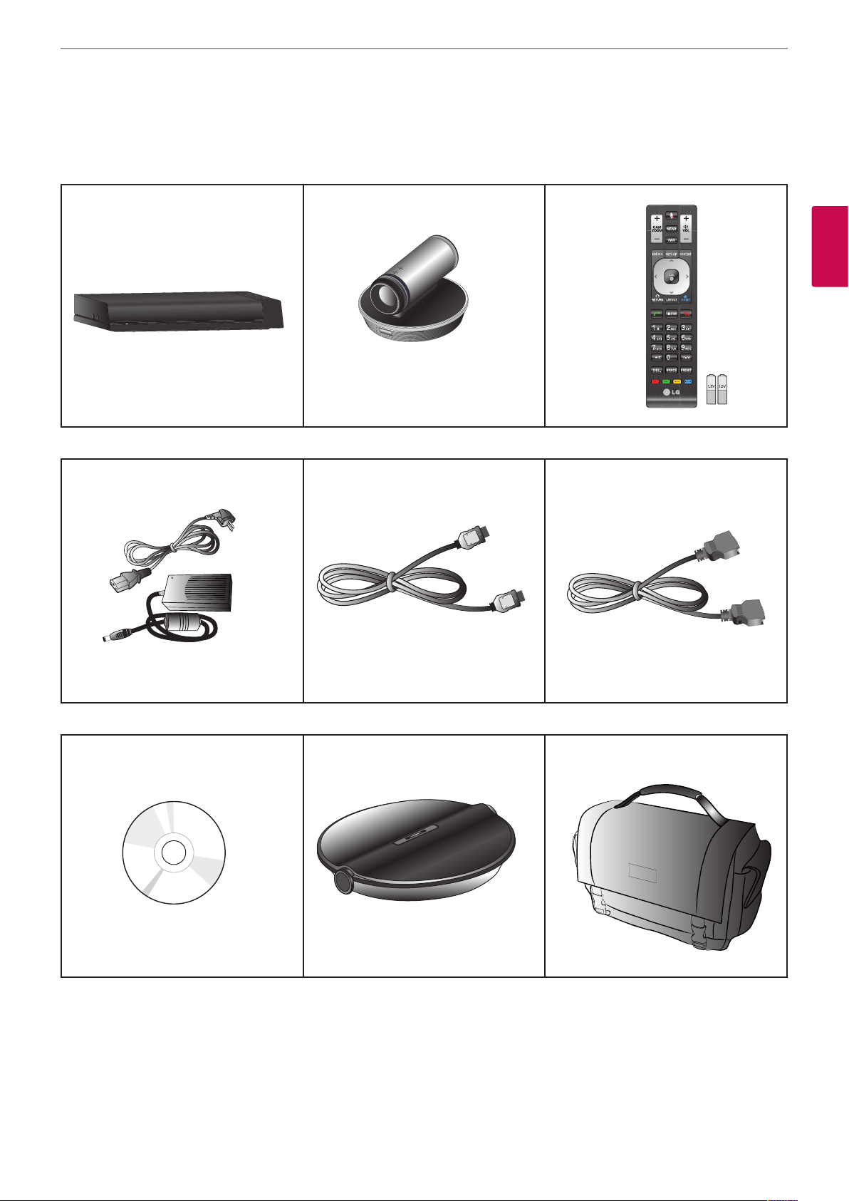
Check your product box for the following items. If there are any missing accessories, contact the local dealer where you purchased your
product. The illustrations in this manual may dier from the actual product and item.
Codec Unit HD Camera Remote Control and Batteries
9
2
Preparation
Power Adapter HDMI Cable Camera Connection Cable
Owner’s Manual CD MicPod Carrying Case
Page 10
Preparation
10
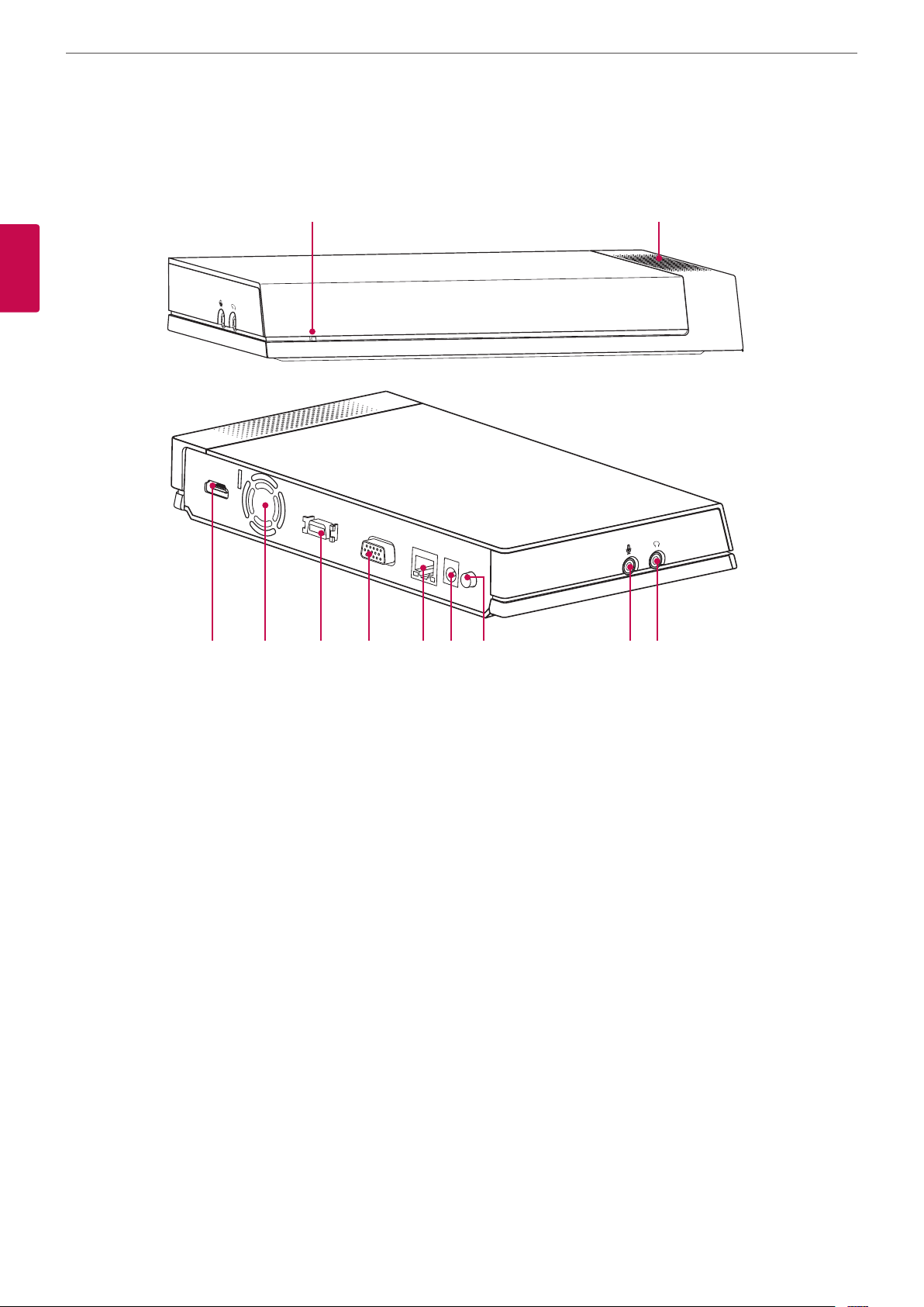
Codec Unit Overview
a b
2
Preparation
HDMI OUT
CAMERA
RGB(PC) IN
LAN
DC IN
POWER
c d e f g h i j k
Power indicator: Lights when the unit turns on.
a
Built-in speaker.
b
HDMI port: Connects the VCS and the display device with an HDMI cable.
c
Cooling fan.
d
Camera connection port: Connects the HD camera.
e
RGB(PC) IN port: Connects the PC with a D-sub cable for presentation.
f
LAN port: Connects to a network via a hub with RJ-45 connector.
g
Power input jack: Connects to a DC 12 V power supply using proper cables.
h
Power button: Turns the unit on or o. You must turn the unit on using the Power button after connecting the power cable. You can
i
use this button to reset the system.
MIC jack: Connects a microphone.
j
AUDIO jack: Connects a headphone.
k
Page 11
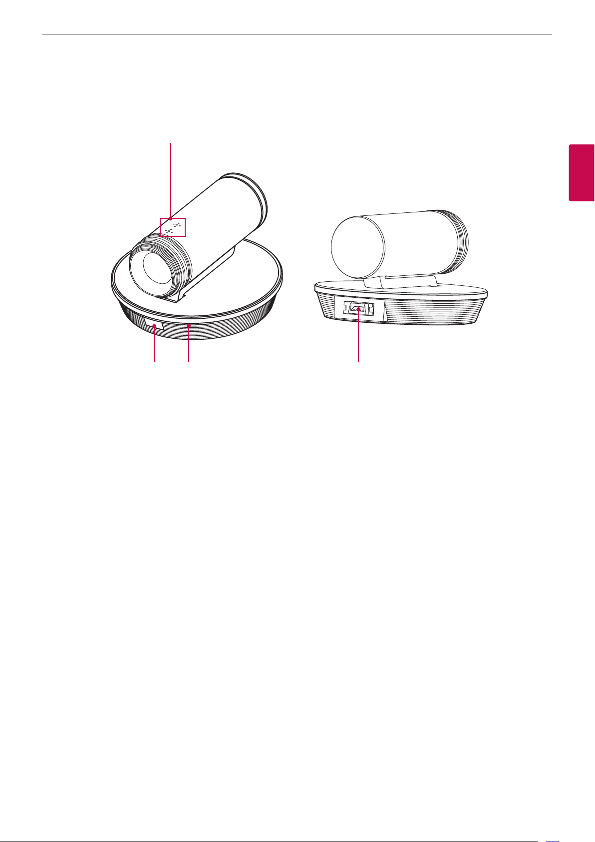
HD Camera Overview
a
Preparation
11
2
Preparation
b c d
Internal microphone
a
Remote sensor: Point the remote control here.
b
Camera activation indicator: Lights when the camera is connected to the codec unit and activates correctly.
c
CAMERA IN port: Connects the codec unit and the HD camera with the supplied camera connection cable.
d
Page 12
Preparation
12
Remote Control
This remote control provides wireless control of all video conference system functions and enables you to navigate the user interface, place
and receive calls and control the far end of the camera connected to the system.
Button Description Button Description
2
Preparation
Use this button to zoom in or
zoom out of the far end camera.
Use this button to adjust the
volume of the system in a call.
Use this button to mute
microphones of the near end
system.
Displays the system or call
information.
Use this button to select the
video input source (camera or
PC) of the near camera.
Use this button to return to the
previous condition.
Use this button to return to the
main screen.
Displays the directory menu. Use this button when you want
Use these buttons to input text
or numbers.
• 1/a/A: Change the input type
among the number, lower
case and upper case.
• DEL.: Delete a character
before the cursor position.
• SPACE: Insert a space at the
cursor position.
Use this button to select the near
or far end camera.
Displays the system setup menu.
• Arrow buttons: Navigate
the menu options. Use this
button to Pan/Tilt control for
far end camera.
• OK: Conrms menu
selections.
Use this button to change the
screen layout.
Use this button when the system
receives a call or manully make a
call.
to hang up the call.
Use this button to set the far end
camera preset.
Function buttons.
Each button function changes as
the condition of the menu and
system operation refers to the
each screen for more details.
Battery Installation
Open the battery cover, replace batteries (1.5 V AAA) matching 2 and 3 ends to the label inside the compartment and then close the
battery cover.
CAUTION
Do not mix old and new batteries as this may damage the remote control.
Page 13
3
Installation
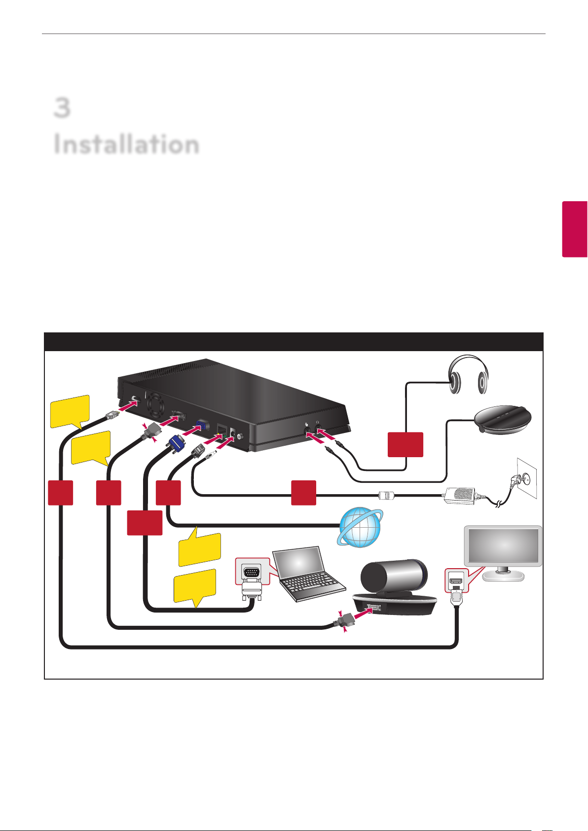
Connections
Installation
13
Precautions
Before setting up the this system, ensure that the monitor, the computer system and other attached devices are turned o.
Connection Overview
The illustration below shows the connections of the system. For specic information of each connection, refer to the next pages.
Connection Overview
HDMI OUT
HDMI
CABLE
CAMERA
CABLE
21
Optional
CAMERA
RGB(PC) IN
LAN
DC IN
POWER
3 4
Optional
3
Installation
LAN
CABLE
D-sub
CABLE
Page 14
Installation
14
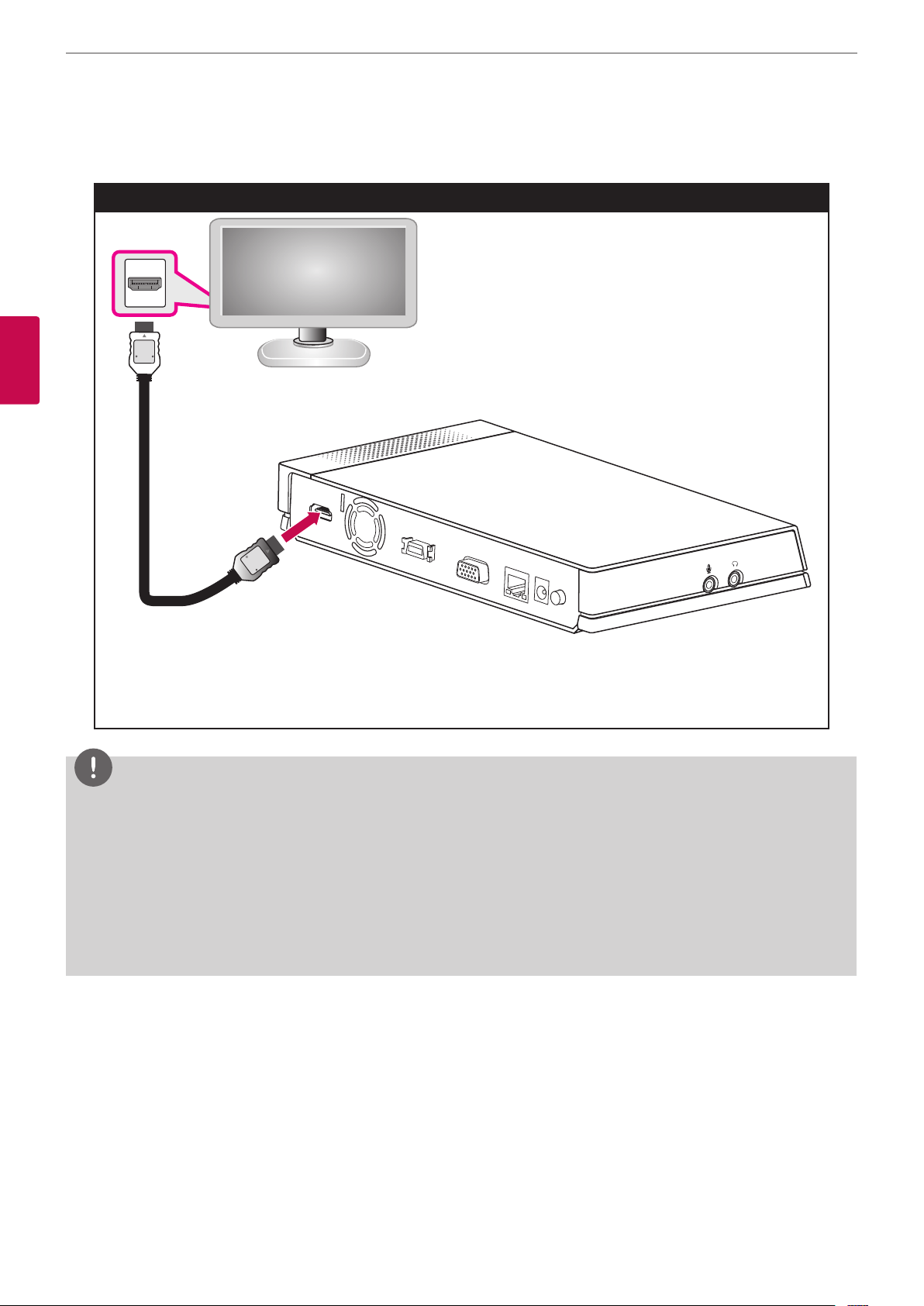
HDMI Connection
Transmits the digital video and audio signals from the system to your monitor with the HDMI cable as shown in the following illustrations.
HDMI Cable Connection
3
Installation
HDMI OUT
CAMERA
RGB(PC) IN
LAN
DC IN
POWER
NOTE
• It is recommended to use the monitor with the 1280X720 mode for the best image quality.
• If you connect the codec unit to the HDMI TV and use the speaker of the TV, the distance between the camera and the TV should be
more than 1 meter.
• The recommended distance between the camera and the user is about 1 m to 2 m.
• If you connect the Codec unit to the DVI port of monitor (TV ) using HDMI to DVI converter, you should hear the audio through built-in
speaker or headphone because DVI does not support audio interface. Please go to Setup > User > Audio > Audio Out and change Audio
Out to “Built-In Speaker” or “Headset Out”.
• If you use the HDMI TV or monitor as a audio output and want to get the high-quality sound, you should run the Audio Out Test for HDMI
at the [System Info > Audio/Video] menu.
Page 15
HD Camera Connection
Connect the HD camera to the camera jack of the codec unit with the supplied camera connection cable as shown in the following
illustrations.
HD Camera Connection
HDMI OUT
CAMERA
RGB(PC) IN
LAN
DC IN
POWER
Installation
15
3
Installation
NOTE
• After connection is completed, adjust the angle of the camera to suit your view.
• If you use the built-in speaker of the codec unit, the distance between the camera and the codec unit should be more than 1 meter.
• The recommended distance between the camera and the user is about 1 m to 2 m.
Page 16
Installation
16
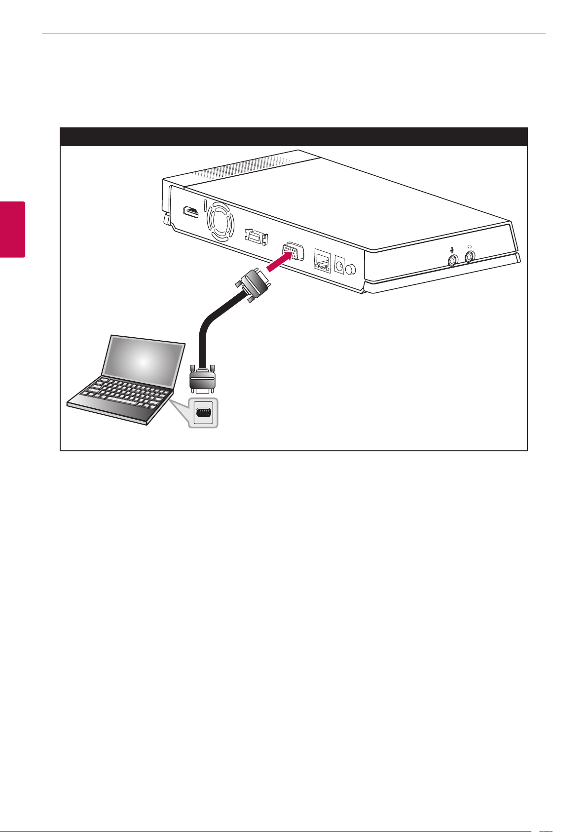
PC Connection
Transmits an analog video signal from your PC to codec unit. Connect the PC and the codec unit with the optional D-sub 15-pin signal cable
as shown in the following illustrations. You can give a presentation to the far-end user with this connection.
PC Connection
HDMI OUT
CAMERA
RGB(PC) IN
3
Installation
LAN
DC IN
POWER
Page 17
Installation
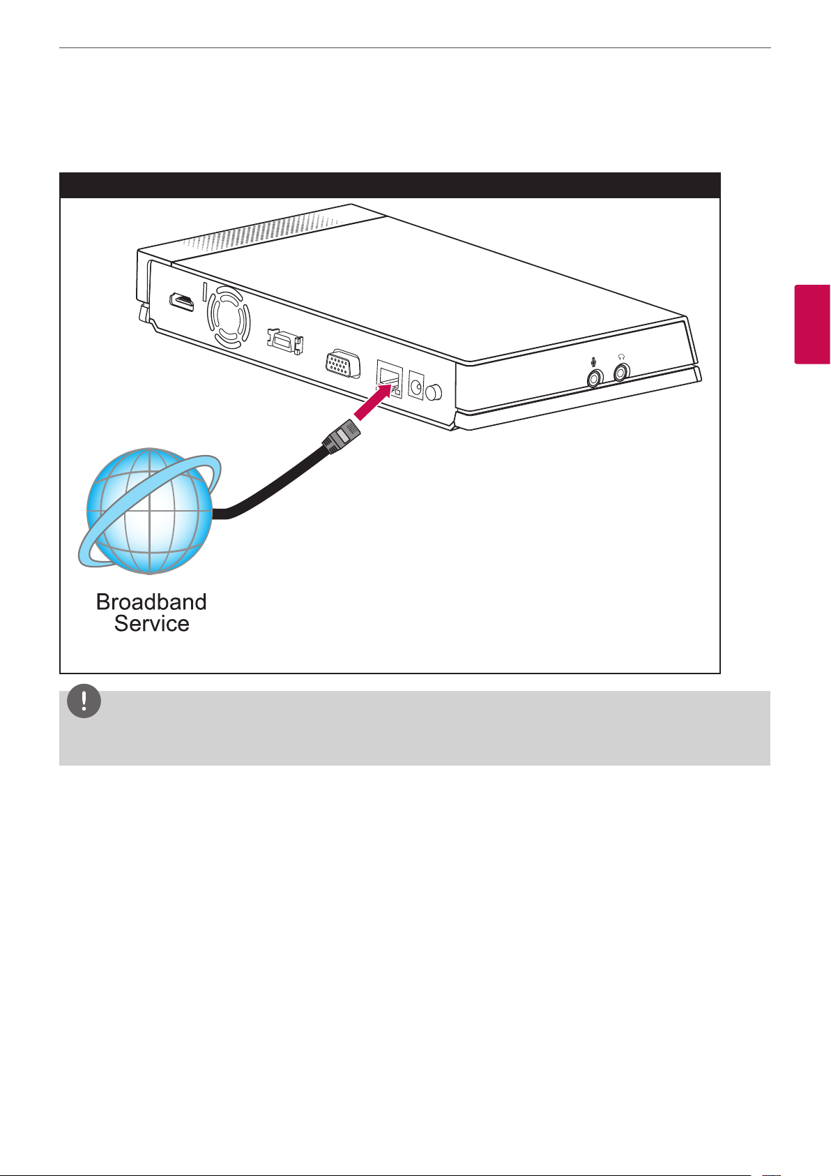
Connecting to a Network
Connect the codec unit’s LAN port to the corresponding port on your router or network using the optional LAN or Ethernet cable with RJ-45
connector.
Network Connection
HDMI OUT
CAMERA
RGB(PC) IN
LAN
DC IN
POWER
17
3
Installation
NOTE
When plugging or unplugging the LAN cable, hold the plug portion of the cable. When unplugging, you should hold the lock of the plug
portion.
Page 18

Installation
18
Connecting a Headphone
Connect a headphone cable to the headphone port of the codec unit as shown in the following illustrations.
Headphone Connection
HDMI OUT
CAMERA
RGB(PC) IN
3
Installation
LAN
DC IN
POWER
Connecting a Microphone
Connect a microphone to the MIC port of the codec unit as shown in the following illustrations.
Microphone Connection
HDMI OUT
CAMERA
RGB(PC) IN
LAN
DC IN
POWER
NOTE
The recommended distance between the microphone and the user is about 1 m to 2 m.
Page 19

Connecting Power
Connect the power cable as shown in the following illustrations.
Power Connection
HDMI OUT
CAMERA
RGB(PC) IN
LAN
DC IN
POWER
Installation
19
3
Installation
CAUTION
You must use a supported adapter. If you connect another adapter not oered with the system, you may cause a malfunction, failure or
re.
System Connection Check
After all of the connections are completed, follow the steps below to check the system operation.
1. Turn on the monitor.
2. Press POWER on the rear of the codec unit.
System booting will commence. When the booting is completed, the initial conguration menu will be displayed.
If it is not displayed, check the device connections and make sure the connections are correctly set.
Now, you can use the system. Do the next conguration.
NOTE
Video out of the system is 720p by default. If the monitor (TV) does not support 720p, press the blue
reboots automatically in 480p.
llll
button 5 times. The system
Page 20

Installation
20
Initial Settings
When you access the VCS for the rst time, the initial setting screen appears. Select a language and customize the basic settings.
1. Insert two AAA batteries matching 2 and 3 correctly into the remote controller.
2. Turn on the unit. System booting will commence. The logo image will be displayed during the system booting.
3. When the booting is complete the initial conguration menu will be displayed.
4. Select the language for the text displayed on the screen.
3
Installation
4-1. Press OK or [ ]. The language list is displayed.
4-2. Select the language using [
4-3. Select [Next] and press OK to go to the next step or press
5. Select the wizard option.
] or [ ] and press OK.
ll
.
Page 21

Installation
5-1. Select one of the below options.
• Start Wizard: Select this option when you want to set the conguration with wizard. If you select this option, follow next steps.
NOTE
It is recommended that you use the Start Wizard option rather than the Manual Setting option.
• Manual Setting: Skip the wizard conguration and display the main setup window. You can set the system conguration manually.
NOTE
If you setup incorrectly in Manual Setting, you may not be able to connect to calls.
21
5-2. Select [Next] and press OK to go to the next step or press
6. Select the time zone.
6-1. Use [ ] or [ ] to select the time zone and press OK.
6-2. Use [
] or [ ] to select the country where the device is located and press OK.
6-3. Select [Next] and press OK to go to the next step or press
ll
ll
.
3
Installation
.
7. Select the one of the network setting options.
• DHCP: Select this option when a DHCP server is installed on the network to allow IP address assignment. With this setting, the IP address
is assigned automatically.
Page 22

22
Installation
7-1. Select this option and press
7-2. Select [Next] and press OK to go to the next step or press
• Static: Select this option when you set the network conguration manually.
7-1. Select this option and press
7-2. Set the below options.
- IP Address: Enter the static IP address of the device.
- Subnet Mask: Enter the subnet mask IP address.
- Gateway: Enter the gateway IP address.
- DNS Server: Enter the IP address to congure DNS servers.
7-3. Select [Next] and press OK to go to the next step or press
8. Enter a descriptive name for the system.
3
Installation
ll
. The IP address information window is displayed.
ll
.
ll
.
ll
.
When using the remote control
8-1. Press OK to edit the system name.
8-2. Enter the system name using the Remote control buttons and press OK to conrm it.
• DEL.: Deletes the previous character at the cursor position.
• SPACE: Inserts space at the cursor position.
• 1/a/A: Changes the input type to numbers, small letters or capital letters.
• Numbers/[
.
#]: Select the numbers, small letters or capital letters as selected input type. Press the button repeatedly to select
*
the character or symbol as you want.
8-3. Select [Next] and press OK to go to the next step or press
ll
.
When using the virtual keyboard.
8-1. Select the virtual keyboard icon and press OK. The virtual keyboard input menu displayed.
8-2. Use the arrow buttons to select a letter and OK to conrm your selection.
• a: Moves cursor to left.
• d: Moves cursor to right.
• Clear: Deletes the previous character at the cursor position.
• Clear All: Clear all the entered characters, numbers and symbols.
• Space: Inserts space at the cursor position.
• a/A/?!: Changes the virtual keyboard settings to small letters, capital letters or symbols.
• OK: Conrm and exit the menu.
• Cancel: Returns to the previous screen.
8-3. Select [Next] and press OK to go to the next step or press
ll
.
9. The Wizard nish message is displayed, press OK to start VCS. The VCS main screen will be displayed.
Page 23

Installation
23
3
Installation
NOTE
• Additionally, refer to the on-screen instructions for each option’s setting.
• If you want to move to the previous option settings, select Previous and press OK or press
l
.
Main Screen Overview
a b c d e f
g h i j k l m n
Page 24

24
3
Installation
Installation
Current Date and Time: Displays the current date and time.
a
Call History: You can make a call by selecting a number from a list of recently dialed numbers.
b
Speed Dial: You can see a list of recently saved speed dial number. You can make a call by pressing a number button of remote
c
controller and selecting a number from list.
Local Video Area: Displays the current input video of the local camera.
d
Directory: Enter the directory tab to see your My Contact and Call History lists.
e
Status Icons
f
Activated Deactivated Description
Not displayed Displays the server status.
Displays the Microphone on or o condition.
Displays the camera status.
Displays the speaker status.
Displays the network status
System Name: Displays the current system name.
g
IP Address: Displays the current IP address of the unit.
h
Text Input Field: Enter the dial numbers or IP address manually.
i
Call Button: Use this button when you want to make a call.
j
Menu Hide: You can hide the user interface elements and you can show the user interface element other remote key.
k
System Info: You can display system status, Audio/Video, Network Utility and Server Status.
l
Setup: You can enter setup menu so you can change system status.
m
Call: You can make a call from text input eld address.
n
System Configuration Menu
The features and options of the VCS system are congured through the setup menu.
1. On the main screen, press SET-UP to access the Setup Menu.
Use the below buttons on the remote control to navigate the menu options.
• Arrow buttons: Use these buttons to select the menu options or adjust the options value.
• OK: Select the option or conrm the setting.
• RETURN: Return to the previous menu or level.
2. Press SET-UP to exit the setup menu.
Page 25

User Settings
General
Installation
25
3
Installation
• System Name: Enter a system name using up to 127 characters. The inputted system name is displayed on the main screen.
1. Press OK.
2. Edit the system name using the virtual keyboard or remote control.
3. Press OK to conrm the setting.
• Call Mode: Select a call mode.
- Audio+Video: When you make a call with audio and video.
- Audio Only: Select this option when you want to call with audio only.
• Answer Type: Select the answer type for the incoming call.
- Auto answer : The system automatically answers the incoming call.
- Manual: You must manually answer incoming calls.
- Do not disturb me : When the system Do Not Disturb feature is enabled, the system displays the main screen. Callers hear a busy
signal and missed calls appear in the Call History. Consider using this feature, for example, if you are using the meeting room for a
purpose other than a video conference and do not wish to be disturbed by incoming calls.
• Screen Saver: When your system is idle during the selected time, it will be activated and the LG logo will be displayed on the monitor.
An incoming call or pressing any button on the remote control automatically invokes the system.
• Language: Select a language for the setup menu and information display.
Page 26

Installation
26
Audio
Adjust settings for audio input and output devices connected to the system.
3
Installation
• Microphone: Select the audio input to use for the active microphone.
- Auto: The system selects the audio input automatically.
- Camera: Audio input can be activated with internal microphone of the HD camera only.
- Ext. Microphone: Audio input can be activated with external microphone device only.
• Ext. Microphone Gain: Adjusts the volume level of the external microphone.
1. Press OK and adjust volume level using the left or right arrow button.
2. Press OK to conrm it.
• Echo Control: Select echo function to ON or OFF.
- On: Select when you want to turn on the echo cancellation.
- O: Select when you want to turn o the echo cancellation.
• Audio Out: Select the location for audio output during calls.
- Auto: The system selects the audio output automatically. If you select this option, basically the unit selects the built-in speaker of
the codec unit. If you connect through the headset jack, audio is output via the connected headset device. If you want to listen
through HDMI, you must set HDMI in the audio out.
- HDMI: Audio is output via the connected HDMI device.
- Built-In Speaker: Audio is output via the built-in speaker of the codec unit.
- Headset Out: Audio is output via the connected headset device.
• RingTone: Select the volume level of the ring tones.
- O: The ring tone volume is o.
- Small: The ring tone volume is set to small.
- Middle: The ring tone volume is set to middle.
- Loud: The ring tone volume is set to loud.
Page 27

Video
Installation
27
3
Installation
• Display Resolution: Select the display resolution of the connected monitor. If you change the resolution, the conrmation window is
displayed and then press OK to reboot the system. You can set the system to 720p or 480p. The default is 720p.
• Camera Brightness: Select the brightness level for the camera. Camera brightness refers to the received amount of light through the
lens of the camera. You can improve dim scenes by manually adjusting the camera brightness.
1. Press OK and adjust brightness using the left or right arrow button.
2. Press OK to conrm the setting.
• Camera Whitebalance: Select the Whitebalance activation mode. Adjust the white balance when video color appears to be unbalanced.
White balance is aected by the type of light source.
- Auto: The whitebalance function is activated automatically.
- Manual: Adjust the white balance level on the Whitebalance level menu.
• Whitebalance Level: Set the white balance level. This option is activated when you set to manual in the [Camera Whitebalance] setting
menu.
1. Press OK and adjust white balance using the left or right arrow button.
2. Press OK to conrm the setting.
• Camera Exposure: Selects the Exposure Menu to match your lighting conditions.
- Auto: The system selects the Auto Exposure Menu to match your lighting conditions. If ickering occurs, try another setting.
• Camera WDR: WDR (Wide dynamic range) feature can be very helpful to cope with very challenging lighting conditions. It is capable
of capturing both of the dark part and bright part and combining the dierences into a scene to generate a highly realistic image as
original scene.
- On: Select when you want to activate the WDR function.
- O: Not used.
Page 28

28
3
Installation
Installation
Date Time
• Time Server: Select time setting method.
- Auto: Set the time server automatically.
- Manual: Set the time server manually. Usable NTP servers are shown below.
NTP Server IP address
time.nist.gov 192.43.244.18
time-a.nist.gov 129.6.15.28
time-b.nist.gov 129.6.15.29
ntp.nasa.gov 198.123.30.132
clock.isc.org 204.152.184.72
time.bora.net 203.248.240.140
• Time Server Address: Enter the IP address or hostname of the time server. This option is activated when you set to manual in the [Time
Server] setting menu.
• Date Format: Select the display format for date.
• Daylight Saving: Set the daylight-savings time.
1. Press OK and then the daylight-savings time setting menu will be displayed.
2. Mark up to set the daylight-savings function.
3. Set the daylight-savings start time.
4. Set the daylight-savings end time.
5. Press OK to conrm the setting. After setting, the daylight-savings option is set to On.
• Time Zone: Select the time zone for your system.
Page 29

Admin Settings
If you select this, the password input window is displayed.
To change the administrator settings, you should input the password. The default administrator password is “1234”.
Enter the password to display the administrator sub-menu options.
Call Settings
General
Installation
29
3
Installation
• Maximum Call Time: Enter the Maximum Call Time from 1 minute to 99999 minutes. After the entered minutes, the system will lose the
call automatically.
• Maximum Bandwidth: Select the maximum amount of network bandwidth to use for video call.
• Outgoing Protocol: Select the protocol to use when attempting to outgoing Call. You can choose H.323, SIP, or Auto. If you select H.323
or SIP, you can make a call selected value. If the far site user does not enable the same protocol, you can’t connect to the far site. If you
selected Auto, you are able to connect moderately with the far site setting. (H.323 is tried before the SIP. If H.323 does not connect, a SIP
call is attempted automatically.)
• SIP Transport Protocol: Select the transport protocol to use during sip outgoing call. You can choose TCP, UDP, or Auto. If you select
TCP or UDP, you can make a SIP call with the selected value. If the far site user does not enable the same transport protocol, you can’t
connect to the far site. If you select Auto, you are able to connect moderately with the far site.
Page 30

Installation
30
H.323
This unit supports the H.323 protocol for placing and receiving video and voice calls. This is used when a gatekeeper function is attempted.
3
Installation
• H.323 Name: Enter the name of the device used when making calls with H.323 with the alphabet, numbers and special characters.
• E.164 Name: Enter the name of the device used when making calls with E.164. This name is used when users register in the gatekeeper
server. If the device is registered on gatekeeper server, the far site user can call this name.
• Security: H.235 128-bit AES security in H.323 calls. When enabled, the system automatically encrypts calls to other systems that have
AES encryption enabled. When set to AES, calls connect, are encrypted only if the far end supports AES encryption. If the far end user
does not support AES encryption, calls are not encrypted.
• Use Gatekeeper: Set to On when you use the gatekeeper function. This unit supports the H.460 protocol for rewall and NAT traversal
of H.323 calls. You must have an H.460 server congured in your environment for this feature to function properly. If you set to On, the
H.460 NAT, Gatekeeper Address and Gatekeeper Port options are enabled to set it.
• H.460 NAT: Set to On when you use the H.460 standard for NAT and rewall traversal.
• GateKeeper Address: Enter the IP address of the primary H.323 gatekeeper.
• GateKeeper Port: Enter the port number of the primary H.323 gatekeeper.
NOTE
You can check the registered status in the Server Status menu of the system information window.
Page 31

SIP
This part is used when users attempt to use a SIP server.
Installation
31
3
Installation
• SIP Name: Enter the name of the device used when making calls with SIP. The SIP name can be used with alphanumeric. If you enter
other characters except letters, numbers, “.”, “-” and “_”, you cannot connect a SIP call.
• Use SIP Server: Set to On when you use the SIP server. If you set to On, the username, password, TLS, register server address, register
server port, proxy server address and proxy server port options are enabled to set it.
• User Name: Enter the SIP server authorization username.
• Password: Enter the SIP server authorization password.
• TLS: When users call, TLS gives safe information about any message. If you set to On, the register server port and proxy server port
options are set to 5061 automatically.
• Register Server Address: Enter the hostname or IP address of the SIP register server.
• Register Server Port: Enter the IP port number of the SIP register server.
• Proxy Server Address: Enter the hostname or IP address of the SIP proxy server.
• Proxy server Port: Enter the IP port number of the SIP proxy server.
Page 32

Installation
32
QoS
You can specify network Quality of Service (QoS) settings.
3
Installation
• Dynamic Bandwidth: Adjusts the bandwidth automatically for the best video bandwidth available.
- On: Dynamic bandwidth function is used.
- O: Not used.
• IP QoS Type: Select the type of TCP/IP Quality of Service (QoS) that your network uses.
- None: Not used.
- DiServ: Set to DiServ (dierentiated services) type of Service (QoS) for audio, video and data packets.
- IntServ: Set to IntServ (integrated services) type of Service (QoS) for audio, video and data packets of the Service (ToS) preference. If
you select this option, the IntServToS option is enabled to set it.
• IntServToS: Select IP Type of Services. This helps a router select a router path when multiple paths are available.
Page 33

Network Settings
IP
You must set the IP address for the call.
Installation
33
3
Installation
• Assignment: Set to STATIC or DHCP for your network conguration.
- DHCP: Select this option when a DHCP server is installed on the network to allow IP address assignment. With this setting, the
IP address is assigned automatically. If you set to this, the IP address, subnet mask, gateway, main DNS and sub DNS options are
dimmed.
- STATIC: Select this option when you set the network conguration manually.
• IP Address: Enter the static IP address of the device.
• Subnet Mask: Enter the subnet mask IP address.
• Gateway: Enter the default gateway IP address.
• Main DNS: Enter the Primary domain name server that translates the hostnames into IP address.
• Sub DNS: Enter the sub DNS server address that backups the main DNS.
Firewall
This function is used when users try to bypass the rewall.
• NAT Conguration:
- Disable: Not used with this function.
Page 34

34
3
Installation
Installation
- Enable: Select when using the static NAT server to traverse your rewall. If you select this option, the NAT Public Address option is
enabled.
• NAT Public Address: Enter the public IP address or hostname of the system.
• Fixed Port: You can x the TCP and UDP port range. If you set to On, the TCP port and UDP port options are enabled.
• TCP Port: Enter the lowest/highest number in the reserved range of the TCP port numbers.
• UDP Port: Enter the lowest/highest number in the reserved range of the UDP port numbers.
Service
• Web Server: If you set to On, you can connect to this device using the web browser.
• Telnet: If you set to On, you can connect to this device using the telnet.
• SSH: If you set to On, you can connect to this device using the SSH.
SNMP
• SNMP: Allows administrators to manage the system remotely using SNMP.
- Disable: Not used with this function.
- Enable: Selects when SNMP is allowed access to this device. If you select this option, the Trap Host and Community options are
enabled.
• Trap Host 1 to 3: Species the IP address of the computer you intend to use as your network management station and to which SNMP
traps will be sent.
Page 35

Installation
• Community: Species the SNMP management community in which you want to enable this system (e.g. lgecommunity or public).
LDAP
LDAP is the ability to read registered address books in the LDAP server. If you connect to an LDAP server, you can conrm in corporate contact
tab in directory.
35
3
Installation
• LDAP:
- Disable: Not used with this function.
- Enable: Selects when the LDAP server allows access to this device.
• Hostname: Enter the host name or IP address of your LDAP server.
• User: Enter the username of your LDAP server.
• Password: Enter the password your LDAP server.
• Base: Enter the base Distinguished Name (DN) used to query your LDAP server.
• Filter: Enter lter strings that you use to specify a subset of data items in an LDAP data type.
IEEE802.1x
Species whether 802.1X network access is enabled. This systems support the following authentication protocols:
• EAP-MD5
• EAP-PEAP
• EAP-TTLS
Page 36

36
Installation
• IEEE802.1x:
- Disable: Not used with this function.
- Enable: Select this option to 802.1x user authentication. If you select this option, identity, password and EAP method options are
enabled.
• Identity: Enter the identity name given to you by your IT administrator. This species the system’s identity used for 802.1X authentication.
• Password: Enter the password given to you by your IT administrator. This species the system’s password used for 802.1X authentication.
• EAP Method: Select the EAP method.
NOTE
When User Use EAP-MD5
If you use EAP-MD5, you do not need to upload any les in the web service.
3
Installation
When User Use EAP-TTLS
1. If you use EAP-TTLS, you must receive ca.pem, client.pem, client.key from the 802.1x network manager.
2. Upload the ca.pem, client.pem, client.key les to the web service of your system as shown in the picture below.
When User Use EAP-PEAP
1. If you use EAP- PEAP, you must receive a ca.pem le from the 802.1x network manager.
2. Upload the ca.pem le to the web service of your system as shown in the picture below.
After Setting 802.1x
1. When you nish these settings, conrm that you can see your IP on the main screen.
2. Perform a ping test in the system info > Network utility > Command.
3. You can now attempt to call other VCS systems.
Page 37

System Settings
Management
Installation
37
3
Installation
• Admin Password: Change the password of the administrator if you want. The password is case-sensitive.
• System Restart: To restart the system, do the below steps.
1. Select Restart and press OK. The warning window is displayed.
2. Select [OK] and press OK. The system will be restarted.
• Setup Initialization: You can initialize the conguration of the setup menu.
1. Select Reset and press OK. The warning window is displayed.
2. Select [OK] and press OK. The system will be initialized and restarted.
• Factory Reset: You can reset the system to its original factory settings.
1. Select Reset and press OK. The warning window is displayed.
2. Select [OK] and press OK. The system will be reset to factory default and
NOTE
restarted.
If you select the [Factory Reset] option, the saved address in the directory will be deleted.
Page 38

Installation
38
System Information
After the conguration setup, you can view the condition of the system.
Press INFO to display the information window.
System Status
You can view the information of the current system status and conguration.
3
Installation
Audio/Video
You can check the audio/video condition.
How to Test the Audio Output
1. Select the Audio Out Test option using the arrow button.
2. Press OK and select the audio output option among the HDMI, Built-In Speaker or Headset Out option.
3. Press OK and select [Start].
4. Press OK again to test the audio output. You will hear three beeps sound, then exit the test. If you cannot hear the beeps, check the
volume level or connection.
Page 39

Installation
NOTE
If you use the HDMI TV or monitor as a audio output and want to get the high-quality sound, you should run the Audio Out Test for HDMI at
the [System Info > Audio/Video] menu.
Network Utility
You can troubleshoot network connection issues with your system using the ping and traceroute utilities in Network Utility.
1. Select the IP Address eld.
2. Press OK to enter a value. If necessary, use 1/a/A to change the method of text entry for text elds or select the keyboard icon to display
the virtual keyboard. After entering a value, hide the keyboard (if you used it to it enter the value) and press OK to exit the eld.
3. Select the option of the command menu.
• Ping: The ping command tests responsiveness between two devices.
• Traceroute: The traceroute command tests responsiveness and traces the path of a packet from one device to the other.
4. Press Start and press OK to test it.
39
3
Installation
Server Status
You can view the server status.
Page 40

Operation
40
4
Operation
Before Using the System
• Before using the LG VCS device, make sure the connections are correct and verify that a proper power supply is used.
• Check the connections of the LG VCS device for the correct conditions.
• Check that the LG VCS device is connected to the network and power is supplied.
• Before using the VCS, make sure the network settings are correct.
• Before placing a call, examine the near end video image from the connected camera to your system. If the image ickers, colors appear
4
Operation
unbalanced or the image appears too dark, you may need to adjust the room lighting or camera brightness and white balance and check
the Camera Exposure menu.
Placing a Call
You can place a call from your system to another VCS system. Begin a call in one of the following ways:
Placing a Call Manually
You can place a call by entering the IP address manually.
1. Select the Text input eld and press OK.
2. Enter an IP address or dial numbers.
Use
3. After entering a value, press OK. is selected automatically.
4. Press OK again to place a call. The call status dialog box is displayed.
to change the method of text entry for text input eld.
The call status dialog box shows the number or IP address that you are attempting to call and the status of the call.
Page 41

Operation
NOTE
• If you cancel the call, press OK during the dialing.
• If the system does not answer the call within about 120 seconds, your system will be disconnected automatically.
• Check the IP address of the system before you place a call. If you do not set the IP address correctly or set the wrong IP address, you can
not make a call.
Placing a Call from the Call History
The list of the Call History stores up to 10 recently dialed phone numbers. The oldest entry in the list is automatically removed when the
system receives a call or places a call after the maximum number of entries has been reached. The last call placed always appears rst on the
list.
1. From the main screen, press the upper arrow button. The Call History tab is expanded.
41
4
Operation
2. Use the left or right button to select an entry.
3. Press OK to place a call. The call status dialog box is displayed.
NOTE
To cancel the call, press OK during the dialing.
Placing a Call from the Directory
The directory stores a list of names and numbers from which you can place calls. To place a call from the directory, follow these steps:
1. From the main screen, press DIRECTORY on the remote control or select [Directory] on the main screen and press OK to access the
directory.
2. Use the arrow buttons to select the entry that you wish to dial.
3. Press OK to place the call. The call status dialog box is displayed.
NOTE
Refer to the Directory setting section for more details.
Page 42

Operation
42
Placing a Call using the Speed Dial
If you set a speed dial number, you can place a call quickly and easily. Press and hold the registered number button for a while until the call
status dialog box appears.
Answering or Rejecting a Call
You can congure your system to automatically answer incoming calls by setting preferences in [User > General > Answer Type] menu as
follows:
• Auto Answer: If you select this option, the system automatically answers the rst incoming call.
• Manual: If you select this option, you must manually answer incoming calls. If your system is congured for answering calls manually,
choose one of the following options when an incoming call arrives:
- Select [Pick up] and press OK to accept the call.
- Select [Reject] and press OK to reject the call.
• Do not disturb me: If you select this option, you can block the all of the call from the other system. The “Do not disturb” message is
4
Operation
displayed in the middle of the top of the main screen. Missed calls appear in the Call History list. Consider using this feature, for example, if
you are using the meeting room for a purpose other than a video conference and do not wish to be disturbed by incoming calls.
NOTE
If you call to another system with the “Do not disturb” function is enabled, the warning window is displayed and the call is disconnected
automatically.
Managing a Call
During a call, you can view information about the status of the call and the identity of the connected caller.
Ending a Call
You can end a call using on the remote control.
Press
Hiding or Showing User Interface Elements
To hide or show the user interface elements at any time during a call, press
Managing Audio
You can adjust the volume of the audio and mute the active microphone.
Adjusting Volume
To adjust the volume in a call, use [VOL + / -] on the remote control. If the volume is set to “0”, audio output is muted and Mute icon
appears in the main screen.
when you want to end a call.
NOTE
l
.
• If the camera is too close to the TV, Echo Performance can be bad condition.
• If you use the built-in speaker of the codec box and the camera is too close to the codec box, Echo Performance can be bad condition.
Page 43

Operation
Muting the Active Microphone
Press on the remote control. When the active microphone is muted in a call, the microphone symbol changes to the muted
43
microphone
icon.
Managing Video Layout
During a call, video from the connected caller appears in your monitor. You can change the screen layout of near and far end video.
Understanding Screen Layouts
Typically, screen layouts appear as the following types:
• A far end participant or a presentation appears on the left window.
• Your site (the near end participant) appears on the right window.
Changing the Screen Layout
1. During a call, press LAYOUT button to display the layout select window.
2. Selects the screen layout using left or right button.
3. Press OK to conrm.
4
Operation
Sharing Content
During a call, you can share digital content.
1. Connect the PC to the system with D-sub cable (see page 16).
2. Let out the video out correctly on your PC (e.g. Fn(Function) + F7 or Dual monitor setting)
3. Press CONTENT. The “Video source is changing...” message will be displayed on the screen. The PC screen is displayed on the near-end
video window.
4. If you press CONTENT again, it returens to the camera screen.
NOTE
This unit supports 640x480, 800x600, 1024x768 and 1280x768 resolutions for PC output resolutions.
Viewing Call Information
You can view the call information.
1. During a call, press INFO.
The current call information window is displayed on the screen.
• Call Protocol: Shows the call protocol.
• Resolution: Shows the resolution, in pixels, of the video image transmitted or received.
• Video Frame Rate: Shows the video frame rate in frames per second.
• Video/Audio Codec: Shows the Video/Audio codec used to compress and decompress the Video/Audio.
• Video Packet loss/Audio Packet loss: Shows the number of packets of data that fail to reach their destination. Packet loss can be caused
by a number of factors, including signal degradation over the network medium, oversaturated network links, corrupted packets rejected
in-transit, faulty networking hardware, maligned system drivers or network applications, or normal routing routines.
• Video/Audio jitter: Shows the variation, in milliseconds, in the time between packets arriving, caused by network congestion, timing
drift, or route changes.
• Video/Audio BW: Shows the amount of Video/Audio data transferred per second in kilobits.
• Cumulative: Shows the up to date count of packets lost in the call.
• Percentage: Shows packet loss as a percentage of the total packets sent.
Page 44

Operation
44
2. Press RETURN to exit.
NOTE
Call information automatically refreshes every 5 seconds.
Get the Snapshot
During a call, you can get a snapshot of the current video image. It will be displayed in the entry of the Call History list.
ll
Press
to take a snapshot.
Managing the Directory
If you have access to the local directory, you can add, remove or edit entries.
4
Operation
Adding an Entry to the Directory
You can create up to 1000 entries in the directory. To add an entry in the directory, follow these steps:
1. From the main screen, press DIRECTORY on the remote control or select [Directory] button the main screen and press OK to access the
directory.
2. Select the My Contact tab using the arrow buttons.
3. Use the arrow buttons to select [Add] and press OK or press
The Add to Directory window is displayed.
lll
.
Page 45

4. Use the arrow buttons to select the Name eld. Press OK to enter a value.
If necessary, use 1/a/A to change the method of text entry for text elds or select the keyboard icon to display the virtual keyboard. After
entering a value, hide the keyboard (if you used it to enter the value) and press OK to exit the eld.
5. Use the arrow buttons to select the Address eld. Press OK to enter a value.
If necessary, use 1/a/A to change the method of text entry for text elds or select the keyboard icon to displayed the virtual keyboard.
After entering a value, hide the keyboard (if you used it to enter the value) and press OK to exit the eld.
6. Use the arrow buttons to select the Group item and press OK. Select a group and press OK.
Operation
45
4
Operation
NOTE
If you make a new group, do the following steps.
6-1. Select [+New] and press OK. The new group window is displayed.
6-2. Enter the new group name and press OK. Select OK of the window and press OK to conrm it.
7. You can conrm saved entry in Speed Dial.
If you want to remove a saved Speed Dial number, you can remove by selecting in the Edit to directory.
7-1. From the main screen, press DIRECTORY on the remote control or select [Directory] on the main screen and press OK to access
the directory.
7-2. Select the My Contact tab using the arrow buttons.
7-3. Use the arrow buttons to move a modifying list and press
lll
.
7-4. Use the arrow buttons to select the Speed Dial item and press OK. Select a number to delete on the list and press OK.
7-5. Yon will see a pop-up window, then press OK.
8. Use the arrow buttons to select a Call Type item and press OK.
Select a call type and press OK.
9. When you have completed the settings, select OK and press OK the remote control.
Editing or Deleting an Entry from the Directory
1. From the main screen, press DIRECTORY on the remote control or select [Directory] on the main screen and press OK to access the
directory.
2. Select the My Contact tab using the arrow buttons.
3. Select the entry you wish to edit and press
The Edit Directory window is displayed. If you delete the entry, select entry and press
displayed and you select [OK] and press OK on the remote controller.
lll
.
llll
or [DEL.]. The Delete Contact window is
Page 46

Operation
46
4. Modify values in the Edit Directory Entry dialog.
4
Operation
Copying an Entry from the Call History
You can copy an entry from the Call History list to the My Contact list.
1. From the main screen, press DIRECTORY or press the arrow up button on the remote control or select [Directory] on the main screen and
press OK to access the directory.
2. Select the Call History tab.
3. Select the entry you wish to copy to the My Contact tab.
4. Press
5. Select [OK] of the Add to Directory window. If you want to edit the item, change the value before you save it.
6. Press OK on the remote control.
lll
. The Add to Directory window is displayed.
Copying an Entry from the Corporate Contact
When LDAP is enabled, Corporate Contact is displayed in the Directory.
1. Enter Corporate Contact tab and select an entry and press
2. Copy to My Contact window is displayed. Select [OK].
3. Press OK on the remote controller.
lll
.
Deleting an Entry from the Call History
1. Enter the Call History.
2. Select the entry you wish to delete and press
3. The Delete History window is displayed.
4. Select [OK] and press OK on the remote control.
llll
or [DEL.].
Page 47

Sorting and Searching
Basically, directories are sorted in the following order: special characters, numbers, characters.
• All: All entries are displayed.
• Alphabet: If the rst letter of a name in the entries is included in the selected alphabet button, the entries are displayed.
• Group: If entries are included in the selected group button, the entries are displayed.
• Search: If the letter or special character in the name is included in the written character on the search eld, the entry is displayed.
Placing a Call when the Device is Registered in Gatekeeper Server
Yon can place a call by entering the registered far site name in gatekeeper server.
1. You must conrm registered far site name in gatekeeper server.
2. Select the text input eld and press OK.
3. Enter a registered far site name. Use 1/a/A to change the method of text entry for text input eld.
4. After entering a value, press OK. is selected automatically.
5. Press OK again to place a call. The call status dialog box is displayed.
NOTE
Operation
47
4
Operation
• If you want to cancel the call, press OK while dialing.
• If you do not answer the call in 2 minutes, the system will disconnect the call automatically.
Making a Call when the Device is Registered in SIP Server
1. You must conrm registered far site name in SIP server.
2. Select the Text input eld and press OK.
3. Enter an registered far site name. Use 1/a/A to change the method of text entry for text input eld.
4. After entering a value, press OK.
5. Press OK again to place a call. The call status dialog box is displayed.
is selected automatically.
NOTE
• If you want to cancel the call, press OK while dialing.
• If you do not answer the call in 2 minutes, the system will disconnect the call automatically.
Using Far End Camera Control
If the far site camera has the PTZ function, you can control the far site camera during the call.
1. Connect to the far site.
2. Press FAR on the remote control.
3. You can control far site camera by pressing CAM ZOOM +, CAM ZOOM - and Arrow buttons.
Using Far End Camera Preset
If the far site camera has the PTZ function or another video source, you can use the preset function.
1. Connect to the far site.
2. Press PRESET on the remote control.
3. Press
4. Move the cursor to the number you want to save.
5. Press
6. Control the far site camera to the location as you want.
7. Press
ll
on remote control and select a video source.
l
on the remote control.
l
. Then you will be able to save the location at that number.
Page 48

Operation
48
8. You can control the far site camera to the saved location by selecting the saved number.
Using SnapShot
You can save entry on directory with the far site user screen picture.
1. Connect to the far site.
2. Press
“Snapshot of Far side is saved” is displayed on the screen.
ll
on the remote control.
NOTE
• You can conrm this snapshot information in the Call History.
• You can save entry with this snapshot information in the My Contact list.
Using the Web Service
4
Operation
You can perform the same conguration from the web interface that is available from the unit. The web interface contains additional features
that cannot be congured on the unit. You can also update the system, upload certication, import or export address book in the web service.
Upgrading your System Software
To upgrade the software for your system, follow these steps:
1. Start the web browser.
The recommended browser is Internet Explorer with Windows.
2. In the Address Box, enter “HTTP://” and the IP Address of the VCS.
You can use the Host Name that you entered in the DDNS setup menu of the VCS.
3. Press ENTER on the keyboard and then the LG VCS web viewer will be displayed.
4. Select the [Setup] tab and enter the Administrator setup menu.
5. Select the [Management] option.
6. Click [Upgrade] of the [System Update] option.
7. Click [Browse].
8. Find and open the rmware le.
9. Click [OK]. The system upgrade status bar is displayed.
10. After upgrading is complete, a conrmation window will be displayed.
Page 49

Click [OK] and the system will be rebooted.
Uploading the Certification File
1. Follow steps 1-5 described in “Upgrading your System Software”.
2. Click [Upload] of the [Upload Certicate] option.
3. Click [Browse].
4. Find and open the certicate le.
5. Click [OK].
Importing or Exporting the Address Book
Operation
49
4
Operation
Exporting the Address Book
1. Follow steps 1-3 described in “Upgrading your System Software”.
2. Select the [Directory] tab.
3. Click the [Export File] menu. The exporting window is displayed.
4. Click [Save].
5. Select the folder and modify the export le name.
6. Click [Save].
Importing the Address Book
1. Follow steps 1-3 described in “Upgrading your System Software”.
2. Select the [Directory] tab.
3. Click the [Import File] menu. The Import CSV File window is displayed.
4. Find and open the address book le and then click [OK]. The imported address will be added and you can see the added address on the
list.
Page 50

Appendix
50
5
Appendix
Troubleshooting
The system power does not turn on.
Symptoms Resolutions
Check the power cable is connected correctly.
Check the input voltage is correct.
Check the main power switch is turned on.
5
Appendix
The system power is turned on but
no video data is displayed on the
monitor.
The subject is not clear enough to
see.
The remote control is not working.
The image is not visible.
If the system power does not turn on even if the power cable is connected correctly,
please contact the service center.
Check the input mode of the monitor.
Unplug the power cable and plug in again.
Adjust the camera brightness and white balance in User > Video tab
Check the batteries.
Make sure that the battery polarity are connected with (+) and (-) matched correctly.
Check the remote control contains two AAA batteries that are in good working
condition.
Verify whether objects are obstructing the sensor on the front of the camera.
Check that the camera cable is connected correctly on device when you use the remote
control.
You can conrm camera connection status as camera icon in main screen
Check that the camera cable is connected correctly on device.
You can conrm camera connection status as camera icon in main screen.
Mued audio reception from the far side may be caused by highly reverberant rooms.
If you are experiencing poor audio reception, add more sound absorbency to the room
and speak in close proximity to the microphone.
Ensure both ends are not muted. Verify that the audio out cables are properly connected
The sound is not audible.
The system does not work with the remote
control.
Video or audio are poor. After connecting to a call, if audio or video do not display normally, users can attempt to
to the monitor and that any external speaker systems are powered and congured
correctly. Also check your Audio Out setting on your audio device (headset, HDMI,
built-in speaker).
Make sure your Audio Out preference in User > Audio for your sound device. If you are
unable to hear the ringer when an incoming call arrives, adjust the ring tone preference
in User > Audio
Reboot the system that is not responding to commands from the remote control.
connect after the codec box is set to low bandwidth.
Page 51

Appendix
You hear a distinct echo. If You Use HDMI TV or Monitor
• Adjust the volume of the HDMI TV or monitor so that it is not too loud.
• Adjust that camera or Mic location is not too close to the HDMI TV or monitor
(approximately 1 m or more).
• Run the Audio out test at the [System info > Audio/Video] menu.
If You Use the Built-in Speaker
• Adjust the volume of the codec (built-in speaker) sound not too large.
• Adjust the camera or Mic location so that it is not too close to the codec box with
the built-in speaker (approximately 1 m or more).
If You Use External Speakers
• Adjust the volume of the external speakers so that they are not too loud.
• Adjust that camera or Mic location is not too close on External speaker
(approximately 1 m or more).
You cannot make a call. If a call does not successfully connect, verify that you have dialed a working number and
that the far end destination is powered on and available. Verify that the network is ready
and available. Network status is indicated at all times on the main screen.
You can conrm that you can connect from your local IP to remote site IP by using the
ping function in the Network utility.
You conrm that you are using proper call protocol (H.323 or SIP). If you set H.323 or SIP
about outgoing protocol, the far site device must be set to the same protocol like near
site.
If you can’t solve this problem, please contact the service center.
Severe freezes and broken video during call. • Try to call using lower video bitrate (e.g. Setup > Admin > Call > General > Maximum
Bandwidth (default 1024 kbps)).
• Check with each site’s IP operators that your video UDP trac is NOT being blocked
by IPS (Intrusion Protection System).
• Check the remote user’s VCS video capability.
- What video resolution is supported: HD 720p, SD 720x480
- What video codec is supported: H.264, H.263
Can’t see the PC screen after I press [CONTENT]. • Check that the D-sub cable is connected properly between the PC and the VCS
system.
• Check that the PC’s video out resolution is properly selected (e.g. 640x480, 800x600,
1024x768 and 1280x768).
• Make sure that you let out the video out correctly on your PC (e.g. Fn + F7 or dual
monitor setting).
The PC screen is shifted after [CONTENT] has
been pressed.
Check that the D-sub cable is connected properly between the PC and the VCS system.
- Change the D-sub cable.
51
5
Appendix
I can’t access the web server. • Check your VCS device’s network accessibility.
1) Check the IP address, subnet, and gateway for typos when using a static IP.
2) Check that the IP address is correctly shown on the OSD using DHCP IP.
3) Connect a dierent PC to the same network and try to ping to your VCS IP address
(e.g. ping 10.177.217.22).
• Try to disable / enable the web server menu via Setup.
1) Go to Setup > Admin > Network >Service > Web Server.
2) Set O and exit from setup.
3) Go back to the Web Server setting, set to On and return to the main screen or try
to turn the power o then back on again.
The remote user is not able to hear your voice. • Check microphone status (see page 24).
• If you select Ext. Microphone in Setup > User > Audio option, check that the Ext.
Microphone is connected properly.
The current input video of the local camera
displays the ickering image.
Use Camera Exposure function to match your lighting conditions in [User>Video> Camera
Exposure] menu.
Page 52

Appendix
52
Open Source Software Notice
The following GPL executables and LGPL libraries used in this product are subject to the GPL2.0/ LGPL2.1 License Agreements:
GPL EXECUTABLES: Linux kernel 2.6, bash, busybox, dhcpcd, mtd-utils, net-tools, procps, sysutils, openldap, openssh, lighthttpd, php, sqlite, netsnmp-5.2.5.1
LGPL LIBRARIES: uClibc, DirectFB, iconv, cairo, gnutls, libcrypt, libgpg-err, libusb.
http://www.gnu.org/licenses/old-licenses/gpl-2.0.html and http://www.gnu.org/licenses/oldlicenses/lgpl-2.1.html .
Also you can obtain a copy of gSOAP public license from http://www.cs.fsu.edu/~engelen/license.html.
This software is based in part on the work of the Independent JPEG Group copyright © 1991 - 1998, Thomas G. Lane.
This product includes
• Freetype library : copyright © 2003 The FreeType Project (www.freetype.org).
• Libpng library : copyright © 2004 Glenn Randers-Pehrson
• Zlib compression library: Copyright © 1995-2002 Jean-loup Gailly and Mark Adler.
• Expat library : copyright © 2006 expat maintainers.
• OpenSSL library :
- cryptographic software written by Eric Young (eay@cryptsoft.com).
- software written by Tim Hudson (tjh@cryptsoft.com).
- software developed by the OpenSSL Project for use in the OpenSSL Toolkit. (http://www.openssl.org)
• libcurl library : Copyright © 1996 - 2008, Daniel Stenberg, daniel@haxx.se
• Libpcap
5
Appendix
This product includes other open source software.
• Copyright © David L. Mills 1992-2006
• Copyright © 1998-2003 Daniel Veillard.
• Copyright © 1998, 1999 Thai Open Source Software Center Ltd.
• Copyright © 1990 The Regents of the University of California.
• Copyright © 1998-2005 The OpenSSL Project.
• Copyright © 1991, 1992 Paul Kranenburg <pk@cs.few.eur.nl>
• Copyright © 1993 Branko Lankester <branko@hacktic.nl>
• Copyright © 1993 Ulrich Pegelow <pegelow@moorea.uni-muenster.de>
• Copyright © 1995, 1996 Michael Elizabeth Chastain <mec@duracef.shout.net>
• Copyright © 1993, 1994, 1995, 1996 Rick Sladkey <jrs@world.std.com>
• Copyright © 1999, 2000 Wichert Akkerman <wakkerma@debian.org>
All rights reserved.
Permission is hereby granted, free of charge, to any person obtaining a copy of this software and associated documentation les (the
“Software”), to deal in the Software without restriction, including without limitation the rights to use, copy, modify, merge, publish, distribute,
sublicense, and/or sell copies of the Software, and to permit persons to whom the Software is furnished to do so, subject to the following
conditions:
THE SOFTWARE IS PROVIDED “AS IS”, WITHOUT WARRANTY OF ANY KIND, EXPRESS OR IMPLIED, INCLUDING BUT NOT LIMITED TO THE
WARRANTIES OF MERCHANTABILITY, FITNESS FOR A PARTICULAR PURPOSE AND NONINFRINGEMENT. IN NO EVENT SHALL THE AUTHORS
OR COPYRIGHT HOLDERS BE LIABLE FOR ANY CLAIM, DAMAGES OR OTHER LIABILITY, WHETHER IN AN ACTION OF CONTRACT, TORT OR
OTHERWISE, ARISING FROM, OUT OF OR IN CONNECTION WITH THE SOFTWARE OR THE USE OR OTHER DEALINGS IN THE SOFTWARE.
Page 53

Specifications
ITEM Specication
System In/Out Port Audio Input (1 x Headset In)
Audio Output (1 x Headset Output)
Camera Input (1 x HD Camera, Microphone In)
D-Sub Video In (1 x VGA )
HDMI Video Out (1 x HDMI - 480P, 720P)
LAN Port :1 x RJ-45, 10/100 Mbps
Power (1 x DC Input - 12 V, 5 A)
Communications H.323, SIP
Appendix
53
Camera Camera Wide-angle lens with 65.4 degree eld of view
Fixed focus with range from 400 mm to innity
Image Device 6.08 mm Color CMOS
Eective Pixels 1 M Pixels
Lens 4.0 mm Fixed lens
Resolution 1280 x720p @ 30 fps
Extra Functions Built-in IR Receiver
Microphone Built-in Microphone
Power DC 5 V
MicPod Microphone Type Electret condenser microphone,
omni directional type
Operating Temperature -40 ºC to 85 ºC
Sensitivity -30 dB ± 3
SNR 58 dB ( 1 kHz at 1 Pa )
Frequency Range 50 Hz to 22 kHz
Cable Spec Thickness : 2 mm, Length : 5 meters
5
Appendix
Case Type Cylinder type
Case Diameter 103.4 mm (Maximum 106.70 mm)
Case Thickness 19.50 mm
Case Total Weight 130 g
Video Stream Resolution Progressive Scan
30 Frame/Sec
Maximum resolutions 720p
Standards H.263, H.264
Page 54

54
Appendix
Audio Features Built-in Ring tone
Full duplex for natural conversations
Echo cancellation for echo-free calls
Automatic noise reduction
Automatic gain control
Standards G.711, G.722, G.722.1, G.722.1C, G.728, G.729
Speaker 2 Watt (Mono)
Other Supported Standards H.323, H.224, H.281 H.225, H.245, H.241, H.460
SIP (RFC 3261),
RFC 3262, RFC 3264, RFC 4566, RFC 3407,
RFC 2976, RFC 3311, RFC 4028,
RFC 2190, RFC 2833, RFC 3984, RFC 4587, RFC 5459
User Interface & Features Easy User Interface
5
Appendix
Graphical User Interface Call Manager
Snapshot / Thumbnail display
Multiple languages supported
Do Not Disturb mode
Security Secure password authentication
Ability to disable HTTP services
H.235 (AES) encryption support including strict compliance
SNMP security alerts
Ability to disable HTTP, SSH and Telnet services
TLS support
IEEE 802.1x support
Intelligent Network
Features
Network Far-End Camera Control (H.224/H.281)
AES (FIPS197, H.235)
NAT / Firewall Client (H.460.17/18/19)
QOS IP Precedence
DiServ (Diereniated Service)
Lost Packet Recovery
Dynamic bandwidth allocation
Directory and Address Book Up to 1000 local directory entries
Save, Remove Redial List features
Missed call notication
LDAP support / H.350 compliant
System Management Web-based system management
Network Time Protocol (NTP)
Firmware Upgrade via Web
Page 55

Power AC Voltage 100-240 V, 50/60 Hz, 1.5 A via external power supply
Environmental Data Operating Temperature 0 ˚C (32 ˚F) to 40 ˚C (104 ˚F)
Operating Humidity 15 % to 85 %, non-condensing
Storage Temperature -20 ˚C (-4 ˚F) to 60 ˚C (140 ˚F)
Storage Humidity 10 % to 90 %, non-condensing
Camera Dimensions Width 106 mm
Appendix
55
Depth (φ)
Height 64 mm (folded), 90 mm
Weight 270 g
Codec Dimensions Width 142 mm
Depth 220 mm
Height 37 mm
Weight 630 g
106 mm
5
Appendix
Page 56

 Loading...