

LG RU-44SZ63D Service Manual

DLP PROJECTION TV
SERVICE MANUAL
CAUTION
BEFORE SERVICING THE CHASSIS,
READ THE SAFETY PRECAUTIONS IN THIS MANUAL.
CHASSIS : MB-042H
MODEL : RU-44SZ63D
CANADA : http//biz.lgservice.com
USA : http//www.lgservice.com
: http//lgservice.com/techsup.html
- 2 -
SAFETY PRECAUTIONS
Many electrical and mechanical parts in this chassis have special safety-related characteristics. These parts are identified by in
the Schematic Diagram and Replacement Parts List.
It is essential that these special safety parts should be replaced with the same components as recommended in this manual to
prevent X-RADIATION, Shock, Fire, or other Hazards.
Do not modify the original design without permission of manufacturer.
General Guidance
An lsolation Transformer should always be used during
the servicing of a receiver whose chassis is not isolated from
the AC power line. Use a transformer of adequate power rating
as this protects the technician from accidents resulting in
personal injury from electrical shocks.
It will also protect the receiver and it's components from being
damaged by accidental shorts of the circuitary that may be
inadvertently introduced during the service operation.
If any fuse (or Fusible Resistor) in this monitor is blown, replace
it with the specified.
When replacing a high wattage resistor (Oxide Metal Film
Resistor, over 1W), keep the resistor 10mm away from PCB.
Keep wires away from high voltage or high temperature parts.
Due to high vacuum and large surface area of picture tube,
extreme care should be used in handling the Picture Tube.
Do not lift the Picture tube by it's Neck.
Leakage Current Cold Check(Antenna Cold Check)
With the instrument AC plug removed from AC source,
connect an electrical jumper across the two AC plug prongs.
Place the AC switch in the on positioin, connect one lead of
ohm-meter to the AC plug prongs tied together and touch other
ohm-meter lead in turn to each exposed metallic parts such as
antenna terminals, phone jacks, etc.
If the exposed metallic part has a return path to the chassis, the
measured resistance should be between 1MΩ and 5.2MΩ.
When the exposed metal has no return path to the chassis the
reading must be infinite.
An other abnormality exists that must be corrected before the
receiver is returned to the customer.
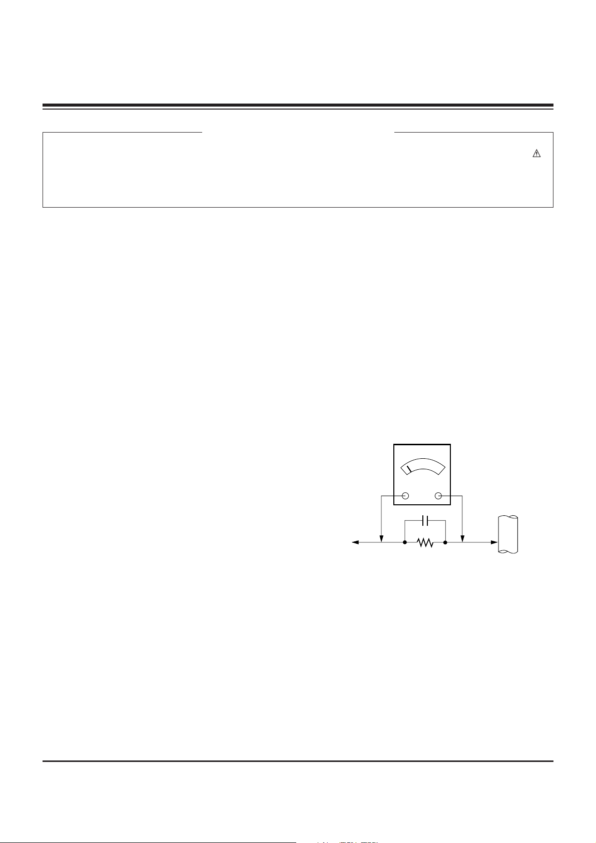
Leakage Current Hot Check (See below Figure)
Plug the AC cord directly into the AC outlet.
Do not use a line Isolation Transformer during this check.
Connect 1.5K/10watt resistor in parallel with a 0.15uF capacitor
between a known good earth ground (Water Pipe, Conduit, etc.)
and the exposed metallic parts.
Measure the AC voltage across the resistor using AC
voltmeter with 1000 ohms/volt or more sensitivity.
Reverse plug the AC cord into the AC outlet and repeat AC
voltage measurements for each esposed metallic part. Any
voltage measured must not exceed 0.75 volt RMS which is
corresponds to 0.5mA.
In case any measurement is out of the limits sepcified, there is
possibility of shock hazard and the set must be checked and
repaired before it is returned to the customer.
Leakage Current Hot Check circuit
CANADA: LG Electronics Canada, Inc. 550 Matheson
Boulevard East Mississauga, Ontario L4Z 4G3
USA : LG Customer Interactive Center
P.O.Box 240007, 201 James Record Road Huntsville,
AL 35824
Digital TV Hotline 1-800-243-0000
1.5 Kohm/10W
To Instrument's
exposed
METALLIC PARTS
Good Earth Ground
such as WATER PIPE,
CONDUIT etc.
AC Volt-meter
IMPORTANT SAFETY NOTICE
0.15uF

- 3 -
SPECIFICATIONS.................................................................4
DESCRIPTION OF CONTROLS...........................................5
ADJUSTMENT INSTRUCTION...........................................12
PRINTED CIRCUIT BOARDS.............................................19
BLOCK DIAGRAM...............................................................29
EXPLODED VIEW...............................................................36
EXPLODED VIEW PARTS LIST.........................................37
REPLACEMENT PARTS LIST............................................38
SCHEMATIC DIAGRAM..........................................................
TABLE OF CONTENTS

- 4 -
Product Specifications
Models
RU-44SZ63D Horizontal Size (Inches) 41.7
Height (Inches) 30.1
Depth (Inches) 14.2
Weight (lbs.) 65
Power Requirement AC 120V, 60Hz
Television System American TV Standard, NTSC, ATSC with STB
Television Channels VHF: 2 - 13
UHF: 14 - 69
CATV: 1 - 125
Power Consumption (W) 240W
Antenna 75 ohm External Terminal for VHF/UHF
Audio Output (W) 12W x 2
Supplied Accessories Remote Control, 2 size AAbatteries, 2 filters.
External Input/Output Ports A/V input (3 set)
A/V output (1 set)
S-Video input (2)
Component input (2 set)
RGB input (1)
DVI input (1)
RGB/DVI audio input (1 set)
Variable audio output (1 set)
Audio center mode input (1)
Calibration port (1)
Design and specifications are subject to change without prior notice.
SPECIFICATIONS
- 5 -
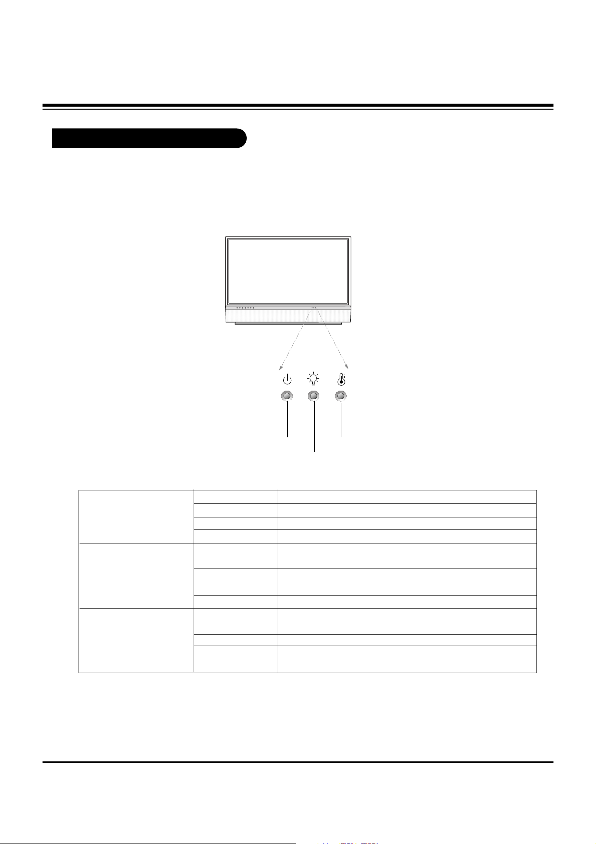
Function Status Indicators
Lamp indicator, operation indicator, and temperature indicator located below the front panel
controls, reveal the operating status of the DLP projection TV.
Operation Indicator
Lamp Indicator
Temperature Indicator
Off Power cord is not connected.
Red Power Cord is connected, TV is in standby mode.
Green TV turns on.
Orange (flashing) Preparing operation in standby mode.
Orange Projection lamp is reaching the end of its life and needs to
be replaced with a new lamp. Contact your service center.
Red (flashing) There is a problem with the lamp or around it. Contact an
authorized service center.
Green (flashing) The lamp cover is not closed.
Orange The projection TV is overheating. Check the blocked vents of
the projection TV and the accumulated dust in the dust filter.
Red The projection TV shut down due to overheating.
Red (flashing) The projection TV shut down, check the cooling fan. Contact
your service center.
Operation Indicator
Lamp Indicator
Temperature Indicator
DESCRIPTION OF CONTROLS
- 6 -
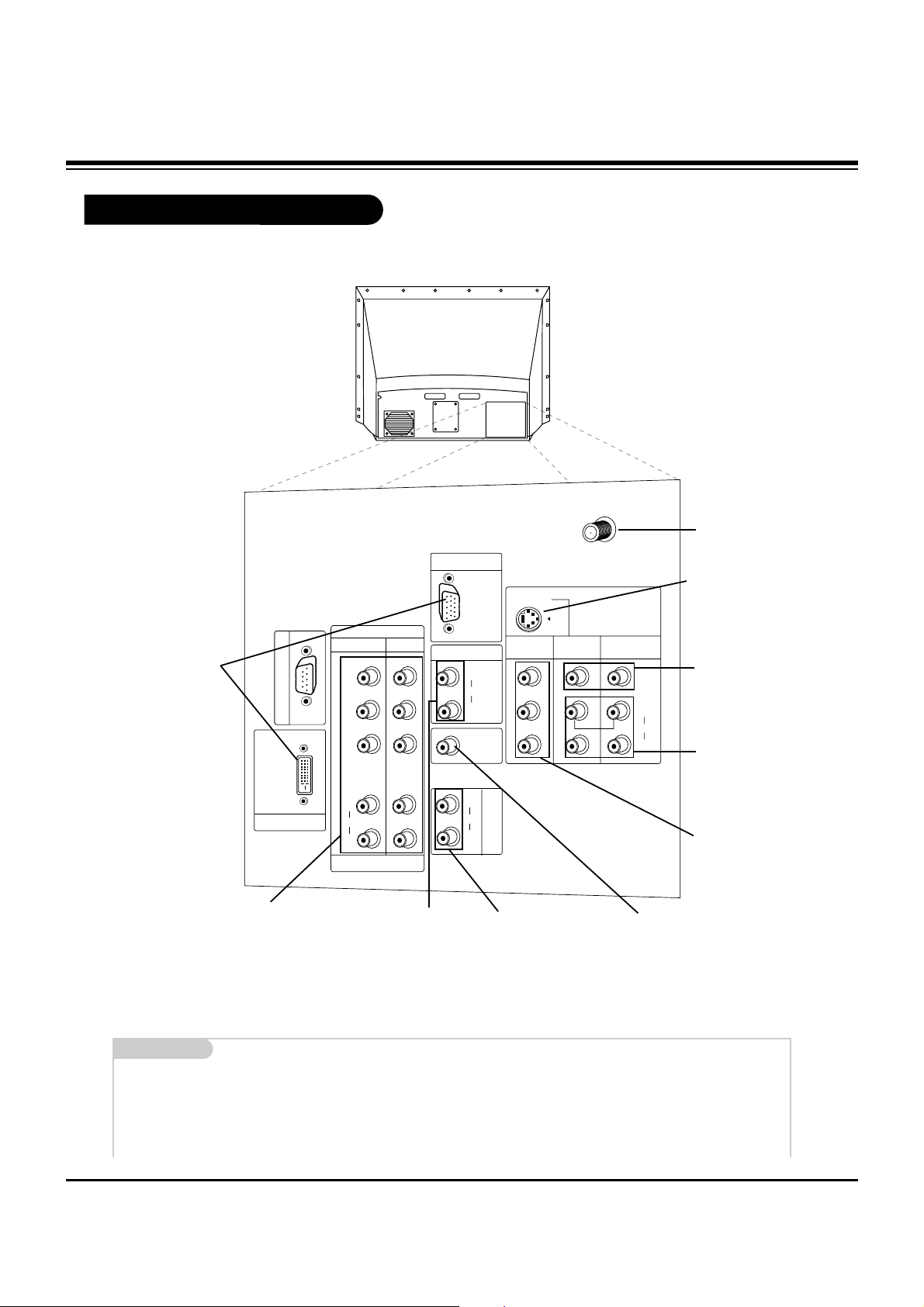
Rear Connections Panel
Mini glossary
JACK A connection on the back of a TV, VCR, or any other A/V device. This includes the RF jack and the Audio/Video jacks that are
color-coded.
SIGNAL Picture and sound traveling through cable, or over the air, to your television screen.
C
A
L
I
B
R
A
T
I
O
N
PC/DTV
(XGA
/480p
/720p
/1080i)
AUDIO
CENTER
MODE IN
P
R
DVI INPUT
DTV/DVD INPUT
COMPONENT
INPUT2 INPUT1
PB
Y
PC/DTV
(XGA
/480p
/720p
/1080i)
RGB INPUT
RGB/DVI INPUT
(R)
(L)
AUDIO
(R)
(L)
AUDIO
(R)
(L)
AUDIO
V
A
R
I
A
B
L
E
A
U
D
I
O
O
U
T
MONITOR
OUT
VIDEO
INPUT 2
VIDEO
INPUT 1
S-VIDEO
(R)
(L)
AUDIO
VIDEO
MONO
+75 Ω
ANT IN
S-VIDEO In
A connection available with
some high-end equipment
that provides even better picture quality for Video 2.
Variable Audio Out
Used to connect either
an external amplifier, or
add a sub-woofer to your
surround sound system.
RF Connector: Antenna
Used to connect analog
cable or antenna signals
to the television, either
directly or through your
cable box.
Video 1 or 2
Connects the video signals from various types
of equipment.
Y, Pb, Pr
DVD Component Video and HD Component
Video
Some top-of-the-line DVD players use what is
called “component video,” for extremely accurate picture reproduction. Refer to your DVD
manual for further information.
Connecting cables and external equipment to your TV.
Monitor Out
Connects to a second TV
or Monitor.
Left/Right Audio
Used for stereo sound
from various types of
equipment.
PC and HD-STB Input
Used to connect from a
PC source or HD-STB
Satellite system.
PC and HD-STB Audio
Input
Used for audio connec-
tions from a PC source or
HD-STB Satellite system.
Audio Center Mode In
Connect to external Dolby
Digital Center “preamp output.”
DESCRIPTION OF CONTROLS
- 7 -
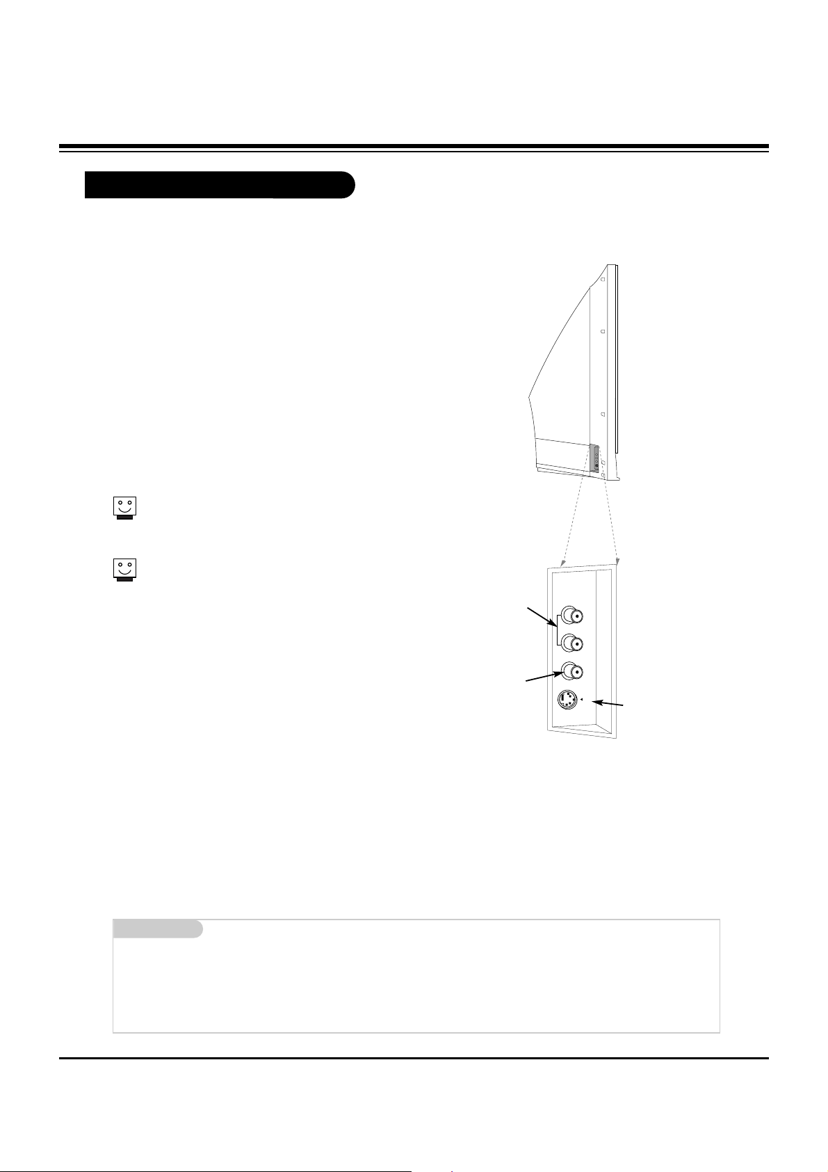
Front Connection Panel
There are four jacks on the left side on your projection TV
that make connecting Audio/Video devices like video games
and camcorders very simple.
The jacks are like those found on the back jack connection
panel. This means that most equipment that connects to
those types of jacks on the rear jackpack, may be connected to the front connection panel.
To use the front jacks as the signal source, select them
using Main Input menu as described on page 25. They will
be named “Front Video” in the Main Input menu.
If you input both Front Video and
S-Video, only the S-Video will
work.
If you’re connecting a video game
device, make sure to change the
picture settings with the EZ
Picture option in the Video menu.
Mini glossary
A/V CABLES Audio/Video cables. Three cable connector—Right audio (red), Left audio (white), and Video (yellow). A/V cables are used
for stereo playback of videocassettes and for higher quality picture and sound from other A/V devices.
A/V DEVICE Any device that produces video or sound (VCR, DVD, cable box, or television).
Front A/V Panel
S-VIDEO
VIDEO
FRONT A/V
AUDIO
(R)
(L)/
MONO
Left/Right Audio
Used for stereo
sound from various
types of equipment.
Video
Connects the video
signals from any
piece of equipment.
S-Video
A connection available on
some very high-end equipment that provides better
picture quality than video
input.
DESCRIPTION OF CONTROLS
- 8 -
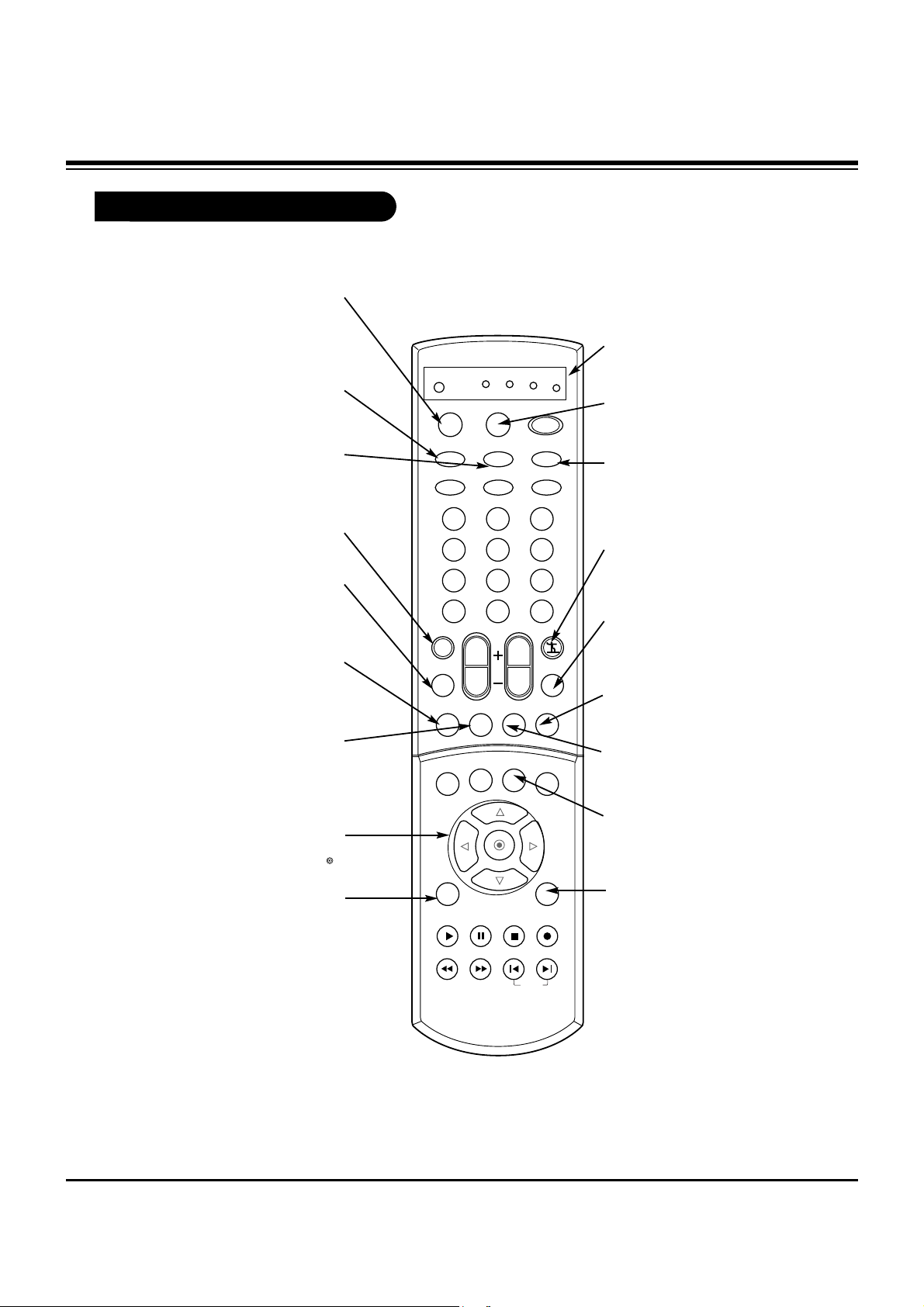
Remote Control Functions in TV Mode
1 2 3
4 5 6
7 8 9
0
TV
MODE
LIGHT
POWER
TV/VIDEO
DVI
RGB
VCR
CABLE
DVD
SAT
MUTE
SWAPPIPCH- PIPCH+
PIP
RATIO
RECORD
STOP
PAUSE
REW
PLAY
FF
MENU EXIT
CC FREEZE
PIP INPUT
VOL
CH
SURF
SAP
VIDEO
COMP2COMP1
FRONT
SKIP
ENTER
FLASHBK
SURF
Scrolls the Surf channel list.
MENU
Brings up the main
menu to the screen.
EXIT
Clears all on-screen displays and returns to TV
viewing from any menu.
FREEZE
Captures and freezes the currentlyviewed main picture.
VIDEO
Adjusts the factory preset picture according to the room.
PIPCH+
Changes to next higher PIP
channel.
SWAP
Switches the picture from
PIP, POP, or twin picture to
the main screen.
MUTE
Switches the sound on or off
THUMBSTICK
Allows you to navigate the on-screen
menus and to adjust the system set-
tings and preferences, by moving to
an option with
F G
and selecting the
highlighted option with .
TV/VIDEO
Selects: Analog, Video1,
Video2, Front video,
Component1-2, RGB, and DVI
input sources.
MODE
Selects the remote operating
mode: TV, VCR, Cable, DVD
and Satellite. Select other oper-
ating modes, for the remote to
control external devices.
FRONT
Selects the front video signal if
a device, such as a camcorder
or game player, is connected
to the front video input jack.
DVI
Selects: DVI-DTV and DVIPC input sources.
SAP
Selects: Mono, Stereo, and
SAP.
PIPCH-
Changes to next
lower PIP channel
PIP
Toggles between PIP, POP
(Picture-outside-Picture)
and Twin picture mode.
LIGHT
Illuminates the remote control keys.
INDICATOR LIGHTS
Show active remote mode
every time any button is
pressed.
D
E
DESCRIPTION OF CONTROLS
- 9 -
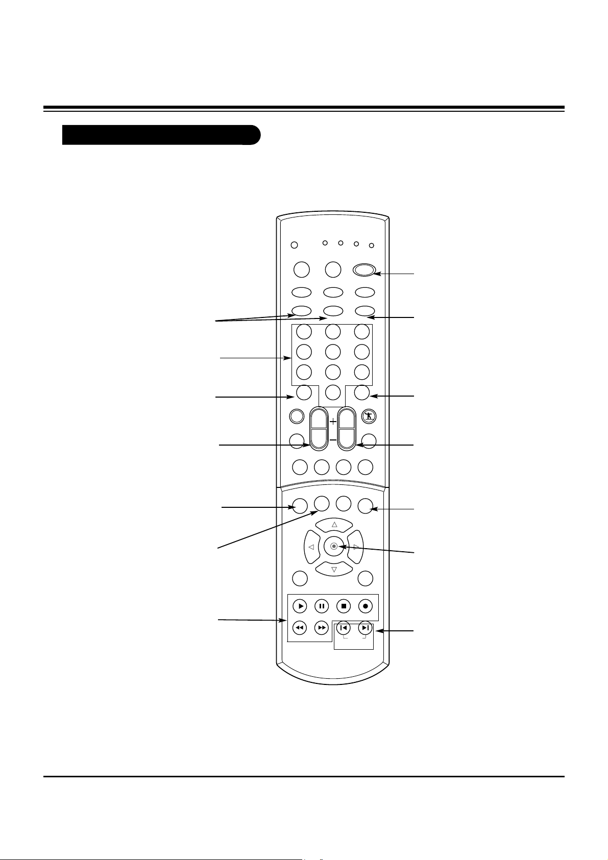
Remote Control Functions in TV Mode
1 2 3
4 5 6
7 8 9
0
TV
MODE
LIGHT
POWER
TV/VIDEO
DVI
RGB
VCR
CABLE
DVD
SAT
MUTE
SWAPPIPCH- PIPCH+
PIP
RATIO
RECORD
STOP
PAUSE
REW
PLAY
FF
MENU EXIT
CC FREEZE
PIP INPUT
VOL
CH
SURF
SAP
VIDEO
COMP2COMP1
FRONT
SKIP
ENTER
FLASHBK
POWER
Turns your TV or any other
programmed equipment on
or off, depending on mode.
CHANNEL UP/DOWN
Scrolls through available
channels in EZ Scan memory.
NUMBER KEYPAD
For direct channel selection and
programming functions.
ENTER
When in the menu system
and other on-screen displays, selects highlighted
options.
RECORD, PAUSE, REW,
FFWD, PLAY, STOP
Control the functions on your VCR.
VOLUME UP/DOWN
Increases/decreases the sound
level.
RATIO
Changes the screen format or
aspect ratio.
SKIP
Playing CDs: Selects
songs.
Playing DVDs: Selects
movie chapters.
COMPONENT 1, 2
Selects component signal sources,
such as DVD or HD receiver.
ENTER
When in the menu system and
other on-screen displays,
selects highlighted options.
FLASHBK
Tunes to the last channel
viewed.
CC
Selects a closed caption mode
for displaying captioning infor-
mation if available on program.
PIP INPUT
Selects the input source for the
sub picture.
RGB
Selects: RGB-DTV and
RGB-PC input sources.
DESCRIPTION OF CONTROLS
- 10 -
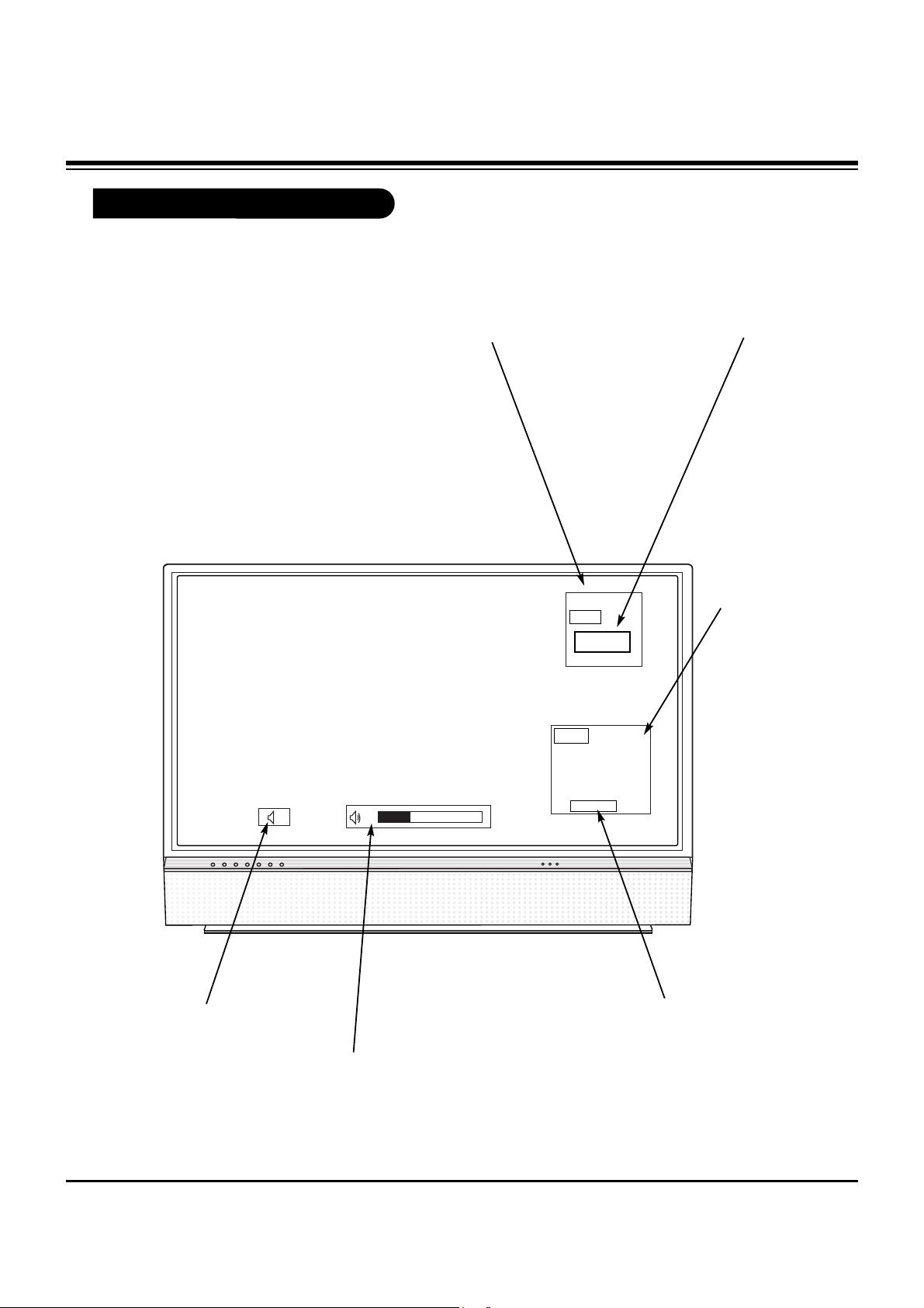
On-Screen Displays
This page describes your on-screen display and information banner options.
10
AM 3:00
TV 13
MONO
TV 6
Main Channel Display
Displays current channel number.
Channel Label
If a channel label has been
set, then it will appear here.
PIP Display
This display
appears when
PIP is active.
Volume
Volume level is displayed while
adjusting the sound.
Mute
Appears
when sound
is muted.
Time
Appears when
pressing the
enter button.
ABC
DESCRIPTION OF CONTROLS
- 11 -
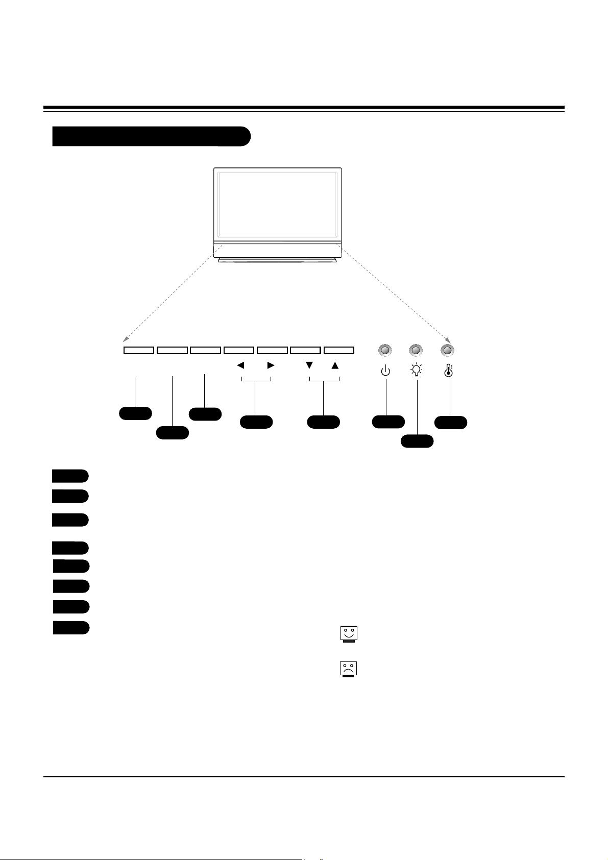
Front Panel Controls
POWER
MENU ENTER VOL CH
1
2
4
3
6
7
8
5
POWER
MENU
ENTER (Same as ENTER button on your
remote control)
VOLUME UP / DOWN
CHANNEL UP / DOWN
Operation indicator.
Lamp indicator.
Temperature indicator.
1
2
3
4
5
6
7
8
The POWER, CHANNEL, TV/VIDEO, and VOLUME
buttons work just as they do on your remote control.
If TV is moved from cold to normal room temperature, humidity may form inside TV, wait 3
hours for TV to adjust to room temperature
before turning it on.
DESCRIPTION OF CONTROLS
- 12 -
ADJUSTMENT INSTRUCTIONS
1. Application Object
These instructions apply to the DLP Projection(Chassis:
MB-042H).
2. Notes
(1) Because this is not a hot chassis, it is not necessary to use
an isolation transformer. However, the use of an insolation
transformer will help protect test equipment.
(2) The adjustments must be performed in the correct
sequence.
(3) The adjustments must be performed in the condition of
25±5°C of temperature and 65±10% of relative humidity if
there is no other specific designation.
(4) The input voltage of the receiver must keep AC 120V,
60Hz in adjusting.
(5) Unless stated otherwise, the set must be operated for at
least 5 minutes prior to adjustments.
The heat-run should be performed with a 100% white
pattern, but reception of a moving picture may also be
possible in unavoidable cases.
3. Composition of Adjustment Mode
(1) Adjustment modes are entered by pressing the ADJ key
on the Service Remore Control, after adjustments press
the ADJ key to exit.
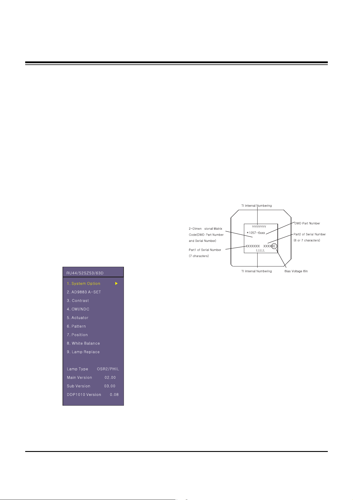
(2) Initial Adjustment mode menu is shown below. <Fig. 1>
(3) As shown <Fig. 1>, using the CH+ (
D), CH- (E) keys, to
select an item, press the ENTER or VOLUME+ (
G) keys to
enter the appropriate item and begin the adjustment.
(4) Change the value of adjustment by using the volume +(
G ),
volume -(
F) keys. To change adjustment item, use the
CH+ (
D), CH- (E) keys in ADJ Mode.
(5) Press the ADJ key to exit after adjustments.
(6) Preparation for Adjustment
1) Connect the power to TV Set and set “Power on”.
2) Allow set to Heat-Run for at least 5 minitues before
adjusting.
4. Driver Board Bin Setting
HD3 DMD sets Bias Voltage Bin setting with S/W.
Only, is not the E Type and case of the different DMD sets a
Bin setting value at adjustment mode. (DDP1010 adjustment
item on subordinate position existence)
<Fig. 2> DMD Marking Locations
<Fig. 1> Adjustment Mode OSD
- 13 -
ADJUSTMENT INSTRUCTIONS
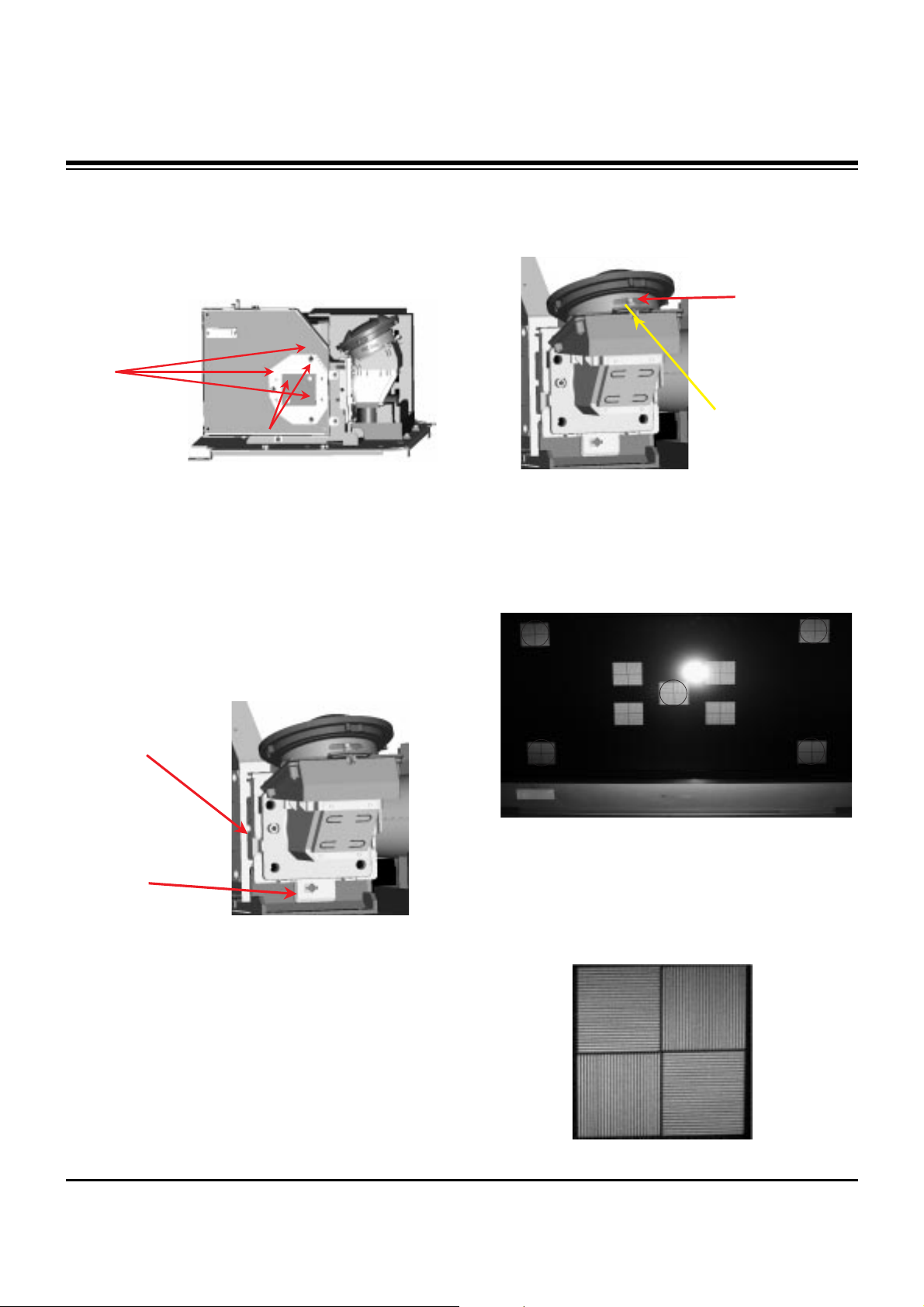
5. Adjusting the Optical Engine
(1) After placing the optical engine on the JIG, adjust
illuminator by adjuting with automatic adjustment the B as
shown <Fig. 3>.
1) When adjust illuminator, search the scope does not fall
in illuminator and Tilt adjustment complete with
automation equipment in that scope.
2) After adjusting, A fix with Screw using automation
equipment.
(2) In order to move Optical system the Tilt is adjusted to
center of the screen, image with top/bottom direction adjust
using B as shown <Fig. 4>.
1) Turn B CW to move the image up, CCW to move the
image down.
2) Turn A CC to move the image right, CCW to move the
image left
(3) After adjusting the illuminator, adjust the focus by using
the focus adjustment screw of projection lens. After
adjusting, fasten the screw tighty and secure with sealer.
[ Note: The focus check point is not the screen center but the
upper/lower screen.
1) <Fig. 6> shows the pattern for Focus adjustment
2) Adjust the 4 green ellipse so that all are in equal focus.
3) If you can’t check the DMD cell bourder at red center
position after adjustment, regard as NG.
4) <Fig. 7> shows the magnified pattern for checking the
focus adjustment
<Fig. 6>
<Fig. 7>
A
B
<Fig. 3>
A
B
<Fig. 4>
Inject the resilock
Screw Fix.
<Fig. 5>
- 14 -
ADJUSTMENT INSTRUCTIONS
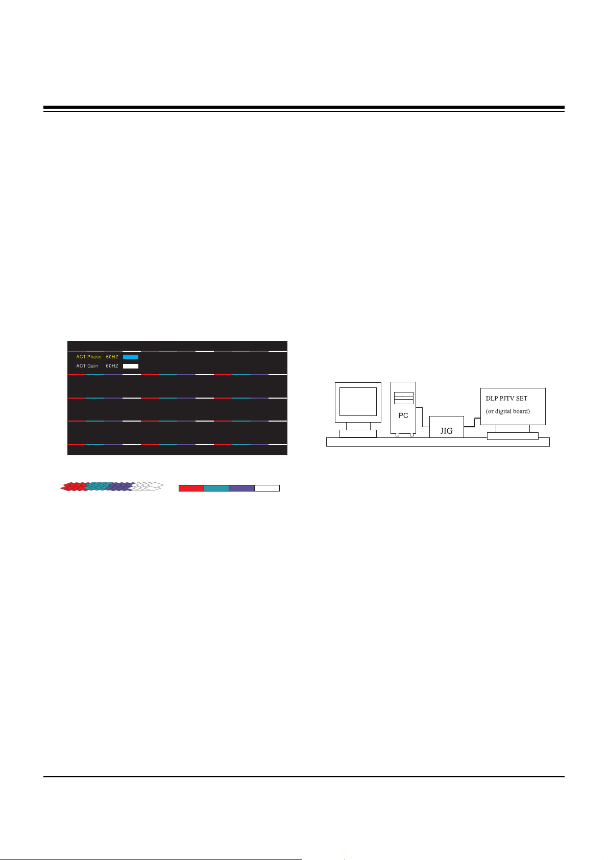
6. Adjusting the Actuator
(Initial Data: ACT Phase=220, ACT Gain=60)
6-1. Required Test Equipment
Service Remote Control
6-2. Preparation for Adjustment
(1) Connect a power source with TV Set and turn TV set on.
(2) Using the Service Remote Control, enter from ADJ to
Actuator.
(3) ACT Gain and Phase is variable and the Tartan plaid of R,
G, B, W Horizontal Line adjust not distinguished not to be.
1) The Phase variable adjust Mutation point of Actuator.
2) The Gain adjust mutation quantity of Actuator.
* The Tartan plaid of R, G, and B adjust not visible not to be.
But, when the R, G and B will not agree, adjust with point R
and G agree.
7. Caution for DMD
(Digital Micro-mirror Device)
7-1. Caution for DMD ESD
(1) Use a grounding strap to prevent ESD (Electrostatic
Dischage) damage when handing the DMD.
(2) Connect the grounding strap to a ground point on the
workbench.
(3) Keep the DMD in an ESD Safe container when not being
used or in transit.
(4) Wearing gloves will help prevent ESD damage and help
preserve the physical condition of the DMD.
(5) All work should be performed in a static free environment.
(6) Use caution and remove any dust particles on the DMD
front glass or back pins/pads.
7-2. Caution for DMD Cleaning
(1) Use caution to prevent scratches to the DMD glass.
(2) When DMD glass stains with dust, polish the front and
back DMD glass with soft cloth. Then, rotate the DMD 180
degrees and polish again.
(3) Do not use pressure when cleaning the DMD. The static
electricity and pollution can damage the DMD.
8. EDID Data Input
8-1. Required Test Equipment
(1) A Jig for adjusting PC, DDC (PC serial to D-sub
connection device)
(2) S/W for writing DDC(EDID data write & read)
(3) D-sub terminal
8-2. Adjustment Preparation and Setting of
Device
(1) Setup as in <Fig. 9> and turn on the PC & JIG.
(2) Operate the S/W for writing DDC(EDID data write & read)
8-3. Sequence of Adjustment
(1) Put the SET(or Digital Board) on the table and turn the
power on.
(2) Input the product code, production week / year, serial
number (if it is not input, write “01”) to the S/W for writing
DDC.
(3) Operate EDID Write command by pressing Function Key
F8.
(4) When “OK” letter appear, completed the Write.
<Fig. 8> Test Pattern
Before Actuator Adjustment After Actuator Adjustment
<Fig. 9> Device Setting Diagram of Input EDID Data
- 15 -
ADJUSTMENT INSTRUCTIONS
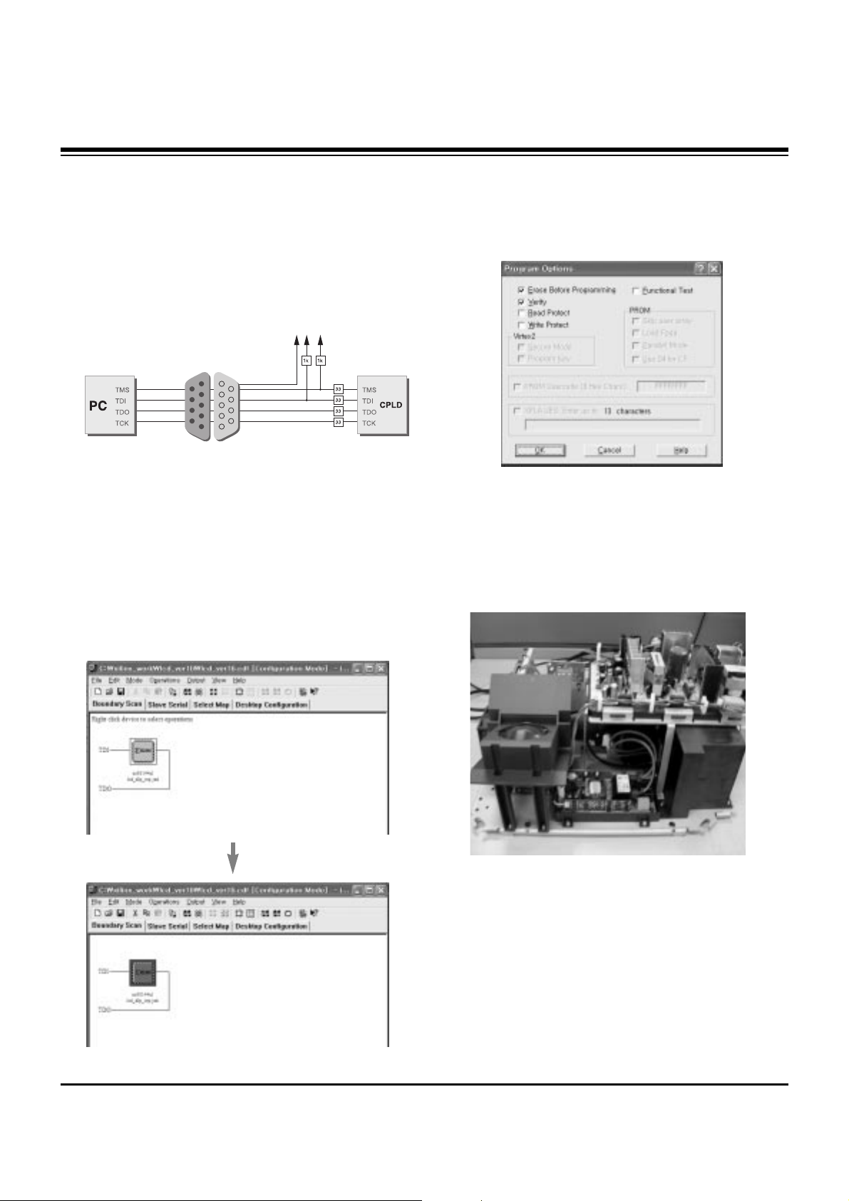
9. CPLD Download Work
9-1. Required Test Equipments &
Preparation for Adjustment
(1) Connect the PC and memory JIG as shown in <Fig. 10>.
(2) Turn on JIG MAIN POWER SW.
(3) After turning on the PC and moniter, operate the device
programming software.
9-2. Adjustment Sequence
(1) Once the program is running, [OPTION MODE
SELECTION] is displayed in the window.
Check the “Load configuration File(.cdf, .pdr)” in this window
and click the finish button
(2) When the screen displays the open window, select the
suitable file(*.cdf) according to model.
(3) IC figure is change to green by clicking it.
(Refer to <Fig. 11>)
(4) Select program options.
(5) Check the [Erase before programming] and [Verify] menu
as shown <Fig. 12> and press the OK button.
(6) At this time, the download starts. The download will finish
in about 10 seconds.
10. Tilt & Keystone Adjustment
(Apply the HD3(DLP) Engine)
10-1. It followed in Screen Condition,
Projector Lens Direction
(1) When the upper portion of the screen is larger than the
bottom: Adjust Projection lens upward.
(2) When the upper portion of the screen is smaller than the
bottom: Adjust Projection lens downward.
3.3V
<Fig. 10 > How to connect the MEMORY JIG and PC>
<Fig. 11>
<Fig . 12>
- 16 -
ADJUSTMENT INSTRUCTIONS
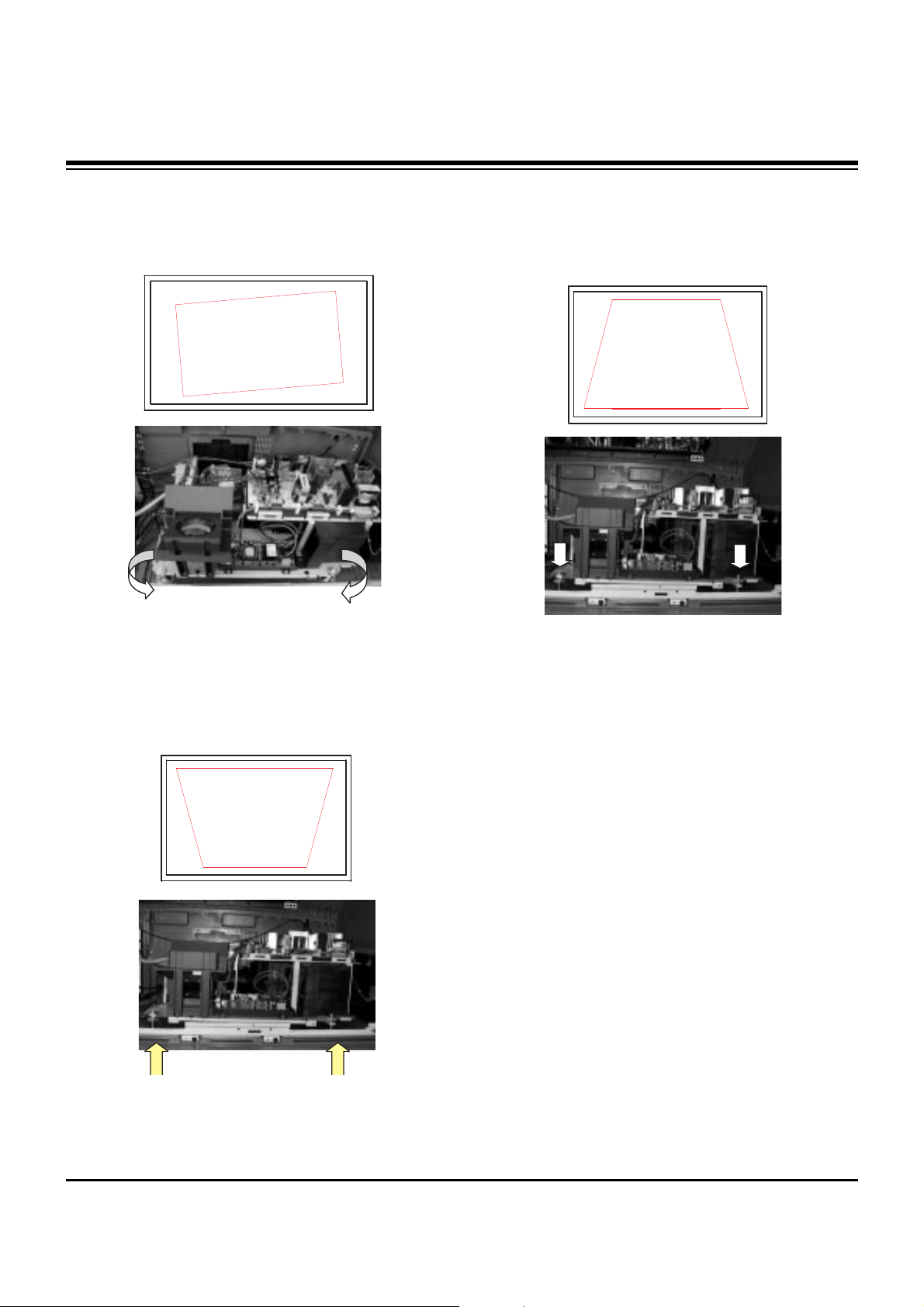
10-2. It followed in Screen Form,
Adjustment Method
(1) When the screen is rotated: Rotate the Engine to adjust
1) Badness Type: Tilt Badness
2) Adjustment Method:
Engine Base rotate with the left/right and fix the
horizontality horizontal line of Cross Pattern
(2) In case of the upper screen size is large bottom screen
size than: upward projector
1) Badness Type: Keystone Badness
2) Adjustment Method:
The Engine Base front part raises at upper direction and
projection lens to be downward projector.
Bottom screen size a lot, fix the top/bottom screen size to
be same as.
(2) In case of
the upper screen size is
smaller
bottom screen
size than:
downward projector
1) Badness Type: Keystone Badness
2) Adjustment Method:
The Engine Base front part down at bottom direction
and projection lens to be upward projector.
Top screen size a lot, fix the top/bottom screen size to
be same as.
11. Screen Position Adjustment
(Base value --> H: 384, V: 168)
11-1. Required Test Equipment
Service Remote Control
11-2. Horizontal Position Adjustment
(1) Press ADJ key on the remote control to enter the
adjustment mode.
(2) Select POSITION in the adjustment menu.
(3) AThe adjustment pattern below appears.
(4) Select H_position with CHANNEL key.
(5) Change data with using the VOLUME keys on the remote
control in order adjust left/right screen semmetry
(6) If symptom is out of adjustable range: N.G.
11-3. Vertical Position Adjustment
(1) Select V_position with CHANNEL key.
(2) Change data with using the VOLUME key on the remote
control in order to adjust up/downscreen semmetry
(3) If symptom is out of adjustable range: N.G.
 Loading...