

LG RU-42PX20-AALZKG Owner’s Manual

MATV
MODEL: RU-i42PX10/11/20
read this manual carefully and completely before
for future reference.
and serial number of the TV in the
the back cover and relate this
require service.
iiiiiiiiiiiiiiiiiiiiiiiiiiiiiiiiiiiiiiii_

Warning
f
WA RNING"
TO REDUCE THE RISK OF ELECTRIC SHOCK DO NOT REMOVE COVER (OR BACK). NO USER
SERVICEABLE PARTS INSIDE. REFER TO QUALiFiED SERWCE PERSONNEL.
_, The ligh'ming flash with arrowhead symbol, within an equilateral triangle, is intended to atert the user to
the presence of uninsumated "dangerous vo_ge" within the product's encEosure that may _ of sufficient
magnitude to constitute a risk of electric shock to persons.
The exclamation point within an equilateral triangle is intended to alert: the user to the presence of impor-
tant oporating and maintenance (servidng) instructions in the tkerature accompanying the appliance.
WARNING:
TO PREVENT FiRE OR SHOCK HAZARDS, DO NOT EXPOSE THiS PRODUCT TO RAiN OR MOISTURE.
CAUTION: TO PREVENT ELECTRIC SHOCK, MATCH WIDE B_DE OF PLUG TO WIDE SLOT, FULLY iNSERT.
I OWER CORD POLARIZATION:
NOTE TO CABLE/TV INSTALLER:
This reminder is provided to ca]i the CA'PC system instaJler s attention to Articte 820-40 of the National Electric Code
(U.S.A.). The _ provides guideJines for proper grounding and, in particular, s_cifles that the cable ground shall be
conne_d to the grounding system of the buiJding, as dose to the point of the c_te ent_ as p_cticaL
REGULATORY INFORMATION:
Th_ equip_nt has _n tested and found to compty with the limits for a Class B digita_ device, pu_uant to Part 15 of
the FCC Rules. These limits are designed to provi_ reasonable protection ag_nst harmful interference when the equip-
ment is operated in a res_n_Jai inflation This equip_nt generates uses and carl radiate radio frequency energy
and, ff not instalie.d and used in accordance w_th the instruct_n manua_ may cause harmful interference to radio corn-
munications. However, there is no guarantee that intefferer_ce wilI not occur in a particular inst_lation. If this equipment
does cause harn_ul interference to radio or teievision reception, which can _ determined by turning the equipment off
and on, the user is encouraged to try to correct the interference by one or more of the following measures:
• Reorient or re_ate the receiving antenna,
, increase the separation between the equipment and receiver.
, Cor_nect the equip_nt into an o_[et on a circuit different from that to which the receiver is connected.
• Consuff the dealer or an ex_densed radio_q'V technician for hetp.
Any changes or modifications not e×pressIy approved by the part;,, responsible for compliance could void the user's
authority to operate the equipment.
CAUTION:
Do not attempt to rr_ this product in any way without wri_en authorization from LG Ei_ronics Unauthor_ed mod-
ification could void the user's a_ority to operate this product.
COMPLIANCE:
The responsible party for this product's compi_nce is
LG E_ectronics U.S.A., [nc
1000 Sylvan Avenue, Eng_ev_od Ctiffs, NJ 07632
1-201-816-2000
ht_43:i/wwwJgusa.cem
2 Plasma TV
Safetyfnstruc#ons
I
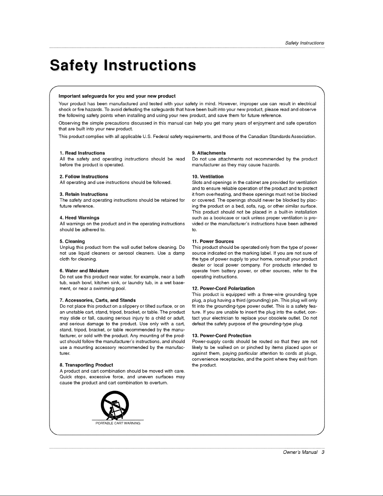
Important safeguards for you and your new product
"Four product has been manufactured and tested with your safety in mind However, improper use can result in e_ectrica]
shock or fire hazards To avoid defeating the safeguards that have been buiit into your new product, please read and observe
the forlowing cafety points when installing and using your new product and save them for future reference.
Observing the simp{e precautions discussed in this m_nual can help you get many years of enioyment and safe operation
that are built into your new product.
This product complies with all _p_icabfe U.S. Fe_ra[ safety requirements, _d those of the C_adian Standards Association.
1. Read Instructions
All the safety and operating instructions should be read
before the product is operated.
2, Follow Instru_ions
All operating and use instructions should be folJov_,
3. Retain |nstru_ions
The s_fety and operating instructions should be retained for
future reference.
4, Heed Wamlngs
All warnings on the product and in the operating instructions
should be adhered to.
5. Cleaning
Unplug this product from the wall out_et before cJeaning. Do
not use tiquid cleaners or aeroso9 cleaners Use a damp
cloth for denning,
6, Water and Moisture
Do not use this product near water, for example, neara bath
tub, wash bow_, kitchen sink, or laundry tub, in a wet base =
merit, or near a swimming poot
7. Accessories, Carts, and Stands
Do not place this product on a s_ippery or tilted surface, or on
an unstable cart, stand, tripod, bracket, or table. The product
may slide or fa]t, causing serious injury to a chitd or adult,
and serious damage to the product, Use only with a cart,
stand, tripod, bracket, or tabme recommended by the manu-
facturer_ or soid with the product Any mounting of the prod-
uct shouM follow the manufacturer's ins_tructions, and should
use a mounting accessory recommended by the manufac-
turer.
8. Transporting Product
A product and cart combin_ion should be moved with care,
Quick stops, excessive force, and uneven surfaces may
cause the product and cart combination to overturn.
g, At_hments
Do not use attachments not recomrr_nd_ by the product
manufacturer as they may cause hazards.
10. Ventilation
Slots and openings in the cabinet are provid_ for ventil_ion
and to ensure retiab_e operation of the product and to protect
it from overheating, and these openings must not be bilked
or covered. The openings should never be b}ocked by plac-
ing the product on a bed, sofa, _g, or other similar surface.
This product shouM not be placed in a buiJt-in installation
such as a bookcase or rack unless proper ventiJa_on is pro*
vided or the manufacturer's instructions have been adhered
to.
11, Power Sources
This product should be operated onmy from the type of power
source indicated on the marking label tf you are not sure of
the type of power suppty to your home consutt your product
dea_er or tocal power company. For products intended to
operate from battery power, or other sources_ refer to the
operating in_nactions.
12_ Power-Cord Polarization
This product is equipped with a three-wire grounding typic
plug, a plug having a third (grounding) pin This plug will oniy
fit into the grounding4ype power outlet. This is a safety fea-
ture. if you are unable to insert the plug into the outJet, con*
tact your e_ectdcian to repJace your obsolete out_et. Do not
defeat the sa{ety purpose of the grounding-type plug,
13. Power-Cord Protection
PowePsupply cords shouM _ routed so that they are not
likely to be walked on or pinched by items placed upon or
against them, paying pa_cuiar attention to cords at pmugs,
convenience receptacles, and the point where they exit from
the product.
PO[_rABL_ CAin ° WARNING
OwneKs Manual 3
SafetyInstructions
Safety Instructions continued
f
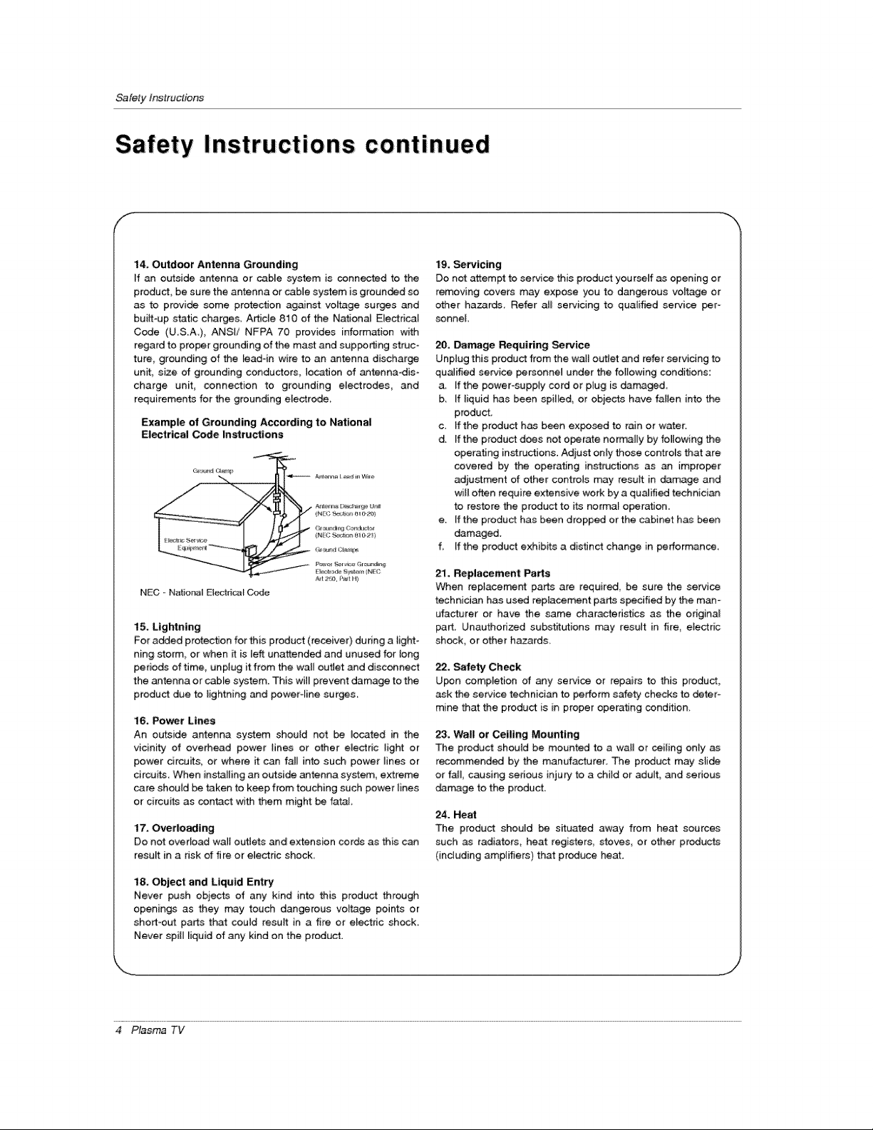
14, Outdoor Antenna Grounding
[f an outside antenna or cable system is connected to the
product, be sure the antenna or cabJe system is grounded so
as to provide some protection ag_nst voltage surges and
builtoup static charges, Article 810 of the National EJectrical
Code (USA), ANSi/ NFPA 70 provides information with
regard to proper grounding of the mast and supping struc-
ture, grounding of the read-in wire to an antenna discharge
unit, size of grounding conductors, location of _tennadis-
charge unit, connection to grounding electrodes_ and
requirements for the grounding eJectrode_
Example of Grounding According to National
Electrical Code Instructions
NEG - Nafio_l Elect_caJ Code
15. Lightning
For a_ed protection for this product (receiver) dudng a light-
ning storm or when _ is left unattended and unused for long
periods of time, unplug it from the weir outie_ and disconnect
the antenna or cable system. This will prevent damage to the
product due to lightning and poweroline surges.
16, Po_r Lines
An outside antenna system shouJd net be located in the
vicinity of overhead power lines or other electric light or
power drcuits, or where it can fall into such power _ines or
circuits. When installing an outside antenna system, extreme
care shouJd be taken to keep from touching such power {ines
or circuits as contact with them might be fatal
17. Overlosding
Do not overload wa_{ outlets _d extension cords as this c_
result in a risk of fire or e_ectric shock
tg, _rvicing
Do not attempt to service this product yourself as opening or
removing covers may expose you to dangerous vottage or
other hazards, Refer atl servicing to qualified service per-
sonnel
20, Damage Requiring Semite
Unptug this product from the wail out_et and refer servicing to
qualified service personne] under the following conditions:
a, If the power-supply cord or plug is damaged
b, _fiiquid has been spilled, or objects have fallen into the
product,
c. If the product has been exposed to r_n or water.
d. [f the product does not o_rate normally by following the
operating inst_ctJons. Adjust only those controls that are
covered by the operating instructions as an improper
adjustment of other contreJs may result in demage and
wilt often require extensive work by a qualified technician
to restore the product to its normal operation.
e. [f the product has been dropped or the cabinet has _en
damaged.
f, If the product exhibits a distinct change in perbrmance,
21. Replacement _rts
When replacement parts are required, be sure the service
technician has used reptacement parts specified by the man-
ufactuter or have the same characteristics as the original
part_ Unauthorized subst_utions may result in fire, etectric
shock, or other hazards,
22, Safety Check
U_n compietion of any service or repairs to this product,
ask the service technician to perform safety checks to deter-
mine that the produ_ is i_ proper operating condition,
23. Wall or Ceiling Mounting
The product should be mounted to a wall or ceiling only
recommended by the manufacturer. The product may stide
or tail, causing serious inju_ to a child or adult, _d serious
derange to the producL
24. Heal
The product shouJd be situated away from heat sources
such as radiators, heat registers stoves or other products
(including ampJifiers) that produce heat.
l& Object and Liquid Entry
Never push obiects of any kind into this product through
openings as they may touch dangerous voltage points or
short-out parts that could result in a fire or el_dc shock.
Never spill liquid of any kind on the p_oduct.
4 Plasma TV

Introduction
Warnings .................................. 2
Safety Instructions ............................. 3-4
Introduction
Controls .......................... 7
Connection Options .................... 8
Remote Control Key Functions .............. 9
Installation
Installation In.ruction ...................... 10
Attaching the TV assembly to the wal{ ........ 10
External Equip_nt Connections ............ 11
Antenna Connection ................... 11
VCR Setup / Cable TV Setup .............. 12
ExternaJ A/V Source Setup .................. 13
DVD Setup ............................ 13
DTV Setup / Monitor Out Setup ............. 14
PC Setup ....................... 15
Operation
Turning the TV On ....................... 16
Menu Language Selection .................. 16
Channel Menu Options
Auto Program: Channe_ Search ............ 17
Manual Program: Adding/Deleting Channels , , ,17
Fine Tuning Adjustment .................. 17
Signa_ Reception Boosler ................. 18
Favorite Channels Setup .................. 18
Picture Menu Options
APC (Auto Picture Contre{) .......... 19
XD 19
Coior Temperature Control ................ 19
Fleshtone ............................. 20
sRGB ................................ 20
Manual Picture Control (Off option) .......... 20
Sound Menu Options
DASP (Digita_ Auto Sound Processing) .... 21
BBE ................................ 21
_VL (Auto Volume Leveler) ................ 21
Manual Sound Control (Off option) .......... 22
Stereo/SAP Broadcaste Setup .............. 22
Timer Menu Options
Aoto C_ock Setup ....................... 23
Manual Clock Setup ...................... 23
On/Off Timer Setup .................. 23
Steep Timer / Auto Off .................... 24
Specia_ Menu Features
Key Lock ............................. 25
ISM (image Sticking Minimization) Method 25
Low Power ........................ 26
XD Demo .............................. 26
Closed Captions ........................ 27
Captions ................................. 27
Caption/Text ........................... 27
Screen Menu Features
Auto Adjus_ent .................... 28
Setting Picture Format ..................... 28
Screen Position ........................ 28
Manual Configure ........................ 29
setting VGA Mode ...................... 29
Screen Adjustments ................... 29
Cinema Mode Setup ................... 29
Luminance Noise Reduction .............. 30
Initializing (Reset to original factory va_ue) ..... 30
Sp_ Zoom ............................ 30
Lock Menu Options
ParentaJ Lock Setup .................... 3t
PiP (Piotu re-In- Pictu re}/Double Window Feature
Watching PiP/Double Window ............. 32
Swapping the PIP/Double Window .......... 32
TV Program selection for PiP .............. 32
_r_ a_ Inp_ Signal Source for PIP/Doub_ Windily .32
Moving the PIP ....................... 32
PIP Size ............................. 32
PIP Transparenc!/ ..................... 32
External Control Device Setup ................ 33._38
IR Codes ................................. 39~40
Troubleshooting Ch_klist ...................... 41
Maintenance ................................. 42
Product Specifications ......................... 42
Warranty ................................. 43--44
Setup and Operation Checklist
Setup and Operation Checklist
(see pages 11 -,15 for available connection and operational setup options.)
1. Unpack TV and a_l accessories,, 5. Turn video source equipment on,
2, Connect ati external video and audio equipment,
see pa_s 12 _ 14,
3 In_'_ll batteries in remote control,
See page 9.
4, -rum TV on,
See page 16,
6 Select viewing source for TV,
See page 9,
7. Fine-tune source image and sound to your personal prefer-
ence or as required by source,
See pages 19 ~ 22.
8 Additional features set up
_e Contents above,
Owner's Manual 5

/nlroduction
!
Ion
What is a Plasma Display Panel (PDP)?
A plasma display panel is the latest display technology. [t is currently the best way to achieve f_ panel displays with excellent
image quality and large screen sizes, that are easily viewabie. The PDP can be thought of as a _scendant of the neon [_p and
it can be also be viewed as a senes of fluorescent lamps.
How does it work?
PDP is an array of cells_ known as pixe_s, whi_ are comprised of 3 sub pixels, corresponding to the colors red, green, and btue.
Gas in a plasma state is used to react w_thphosphors in each sub-pixel to produce colored light (red, green, or blue). These phos-
phors are the same types used in Catho_ Ray Tube (CRT) devices such as televisions and common computer monitors.
You get the dch, dyn_ic colors that you expecL Each sub=pixe[ is individually contre1_ed by advanced electronics to produce over
16 million different colors. All of this means that you get perfect images that are easily viewable in a display that is _ess than 5
inches thick.
160 ° - Wide ang|e range of vision
Your flat panel plasma screen offers an exceptionally broad viewing angle --over 160 degrees. This means that the display [s
c_ear and visible to viewers anywhere in the room who can see the screen.
Wide Screen
The screen of the Plasma Display is so wide that your viewing experience is as if you are in a theater
Multimedia
Connect your plasma display to a PC and you can use itfor conferencing, games, and _nternet browsing. The Picture4n_Picture
feature allows you to view your PC and video images simul_neously.
Versatile
The lightweight and thin size makes it easy to in_ll your plasma display ina variety of locations where conventional TVs will not
The PDP Manufacturing Process: a feet minute colored dots may be present on the PDP s_creen
The PDP (Plasma Display Pane[), which is the display device of this product is composed of 0.g to 2_2 million ceils A few cell
defects wi[[ nora-.airy occur in the PDP manufacturing process, Several tiny, minute colored dots visible on the screen should be
acceptable, This also occurs in other PDP manufacturers products The tiny dots appearing d_s not mean that this PDP is defec-
tive, Thus a few cell defects are not sufficient cause for the PDP to be exchanged or returned Our production technology mini °
mizes these ceil defects during the manufacture and operation of this product
Cooling Fan Noise (RU-50PX10/11/20 only)
[n the same way that a fan is used in a PC computer to keep the CPU (Centram Processing Unit) cool, the PDP is equipped with
cooling fans to cool the Monitor and improve its reliability, Therefore, a ced_n leve_ of noise could occur while the fans are operat-
ing and cooling the PDP,
The fan noise doesn't have any negative effect on the PDP's efficiency or re_iabimity: The noise from these fans is norma_ during the
operation of this product 'We hope you understand that a certain _evel of noise from the cooting fans is acceptable and is not suffi-
cient cause for the PDP to _ exchanged or returned.
6 Plasma TV
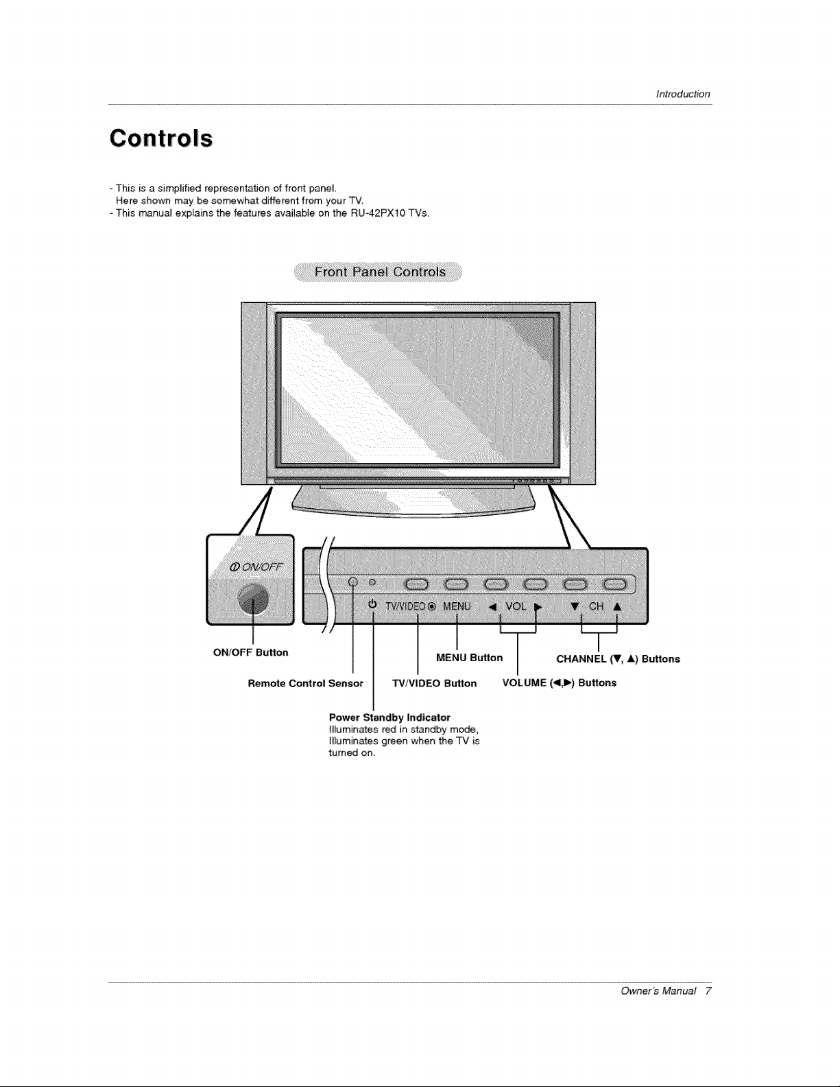
This is a simplified representation of front panel.
Here shown may be somewhat different from your "FV.
o This m_nua_ explains the features avaJ_abJe on the RU42PX10 TVs,
Introduction
ON/OFF Button
Remote Control Sensor
MENU Button CHANNEL (Y, A) Buttons
TV/VIDEO Button VOLUME (_l,ll_)Buttons
Power Standby Indicator
Illuminates red in standby mode,
H_uminates green when the TV is
turned on,
Owner's Manual 7
tnlroduction
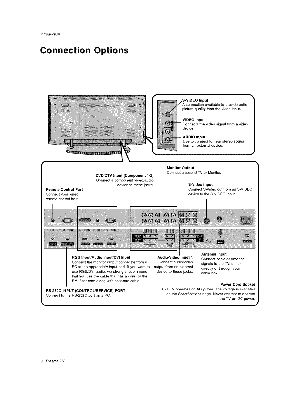
Remote Control Port
Connect your wired
remote control here,
DVD/D'FV Input (Component 1-2)
Connect a component video/audio
device to these jacks
,S-VIDEO
picture qual_¢ than the video input
VIDEO Input
device.
AUDIO input
Use to connect to hear stereo sound
from an extema_ device.
Monitor Out:put
Connect a second TV or Monffor.
S-Video Input
Connect S-Video out from an S-VIDEO
device to the S_VIDEO input.
RGB InputfAudIo input/DVl Inp_
Connect the monitor output connector from a
PC to the appropriate input port. If you want to
use RGB/DW audio, we strongly recommend
that you use the cable that has a core, orthe
EMt filter core along wffh separate cable_
RS-232C INPUT (CONTROLtSERVICE) PORT
Connect to the RSo232C port on a PC,
8 Plasma TV
Audio/Video Input i
Connect audio!video
output from an external
device to these jacks.
Antenna _nput
Connect cable or antenna
signals to the TV, effher
directFy or through your
cable box.
Power Cord Socket
This rv operates on AC power. The vol_ge is indicated
on the S_dfications page. Never attempt to o_rate
the TV on DC power.
Remote Contro! Key Functions
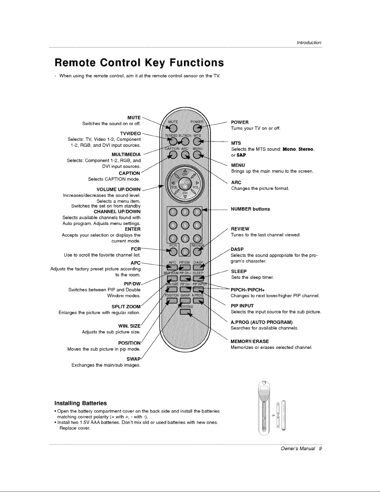
- When using the remote contrel_ aim it at the remote control sensor on the T'v'_
Introduction
MUTE
Switches the sound on or off.
TVVIDEO
SeWects: TV, Video 1-2, Com_nent
1-2, RGB, and DVt input sources.
MULTIMEDIA
Selects: Component 1-2, RGB, and
DVt input sources
Selects CAPTION mode.
VOLUME UP/DOWN
Increases/decreases the sound level
Selects a menu item_
Switches the set on from standby
CHANNEL UP/DOWN
Selects available channels found with
Auto program. Adjusts menu settings
ENTER
Accepts your selection or displays the
current mode,
Use to scrotl the favorite channei _ist,
Adjusts the factory preset picture according
to the room,
Switches between PtP and Doubte
Window modes.
SPLIT
Enlarges the picture with regufar ration.
WIN,
Adju_s the sub
Moves the sub picture in pip mode.
SWAF
Exchanges the main/sub images.
POWER
Turns your TV on or off,
' -- M'rs
Selects the MTS sound: Mono, Stereo,
or SAP.
MENU
Brings up the main menu to the screen,
ARC
Changes the picture format.
NUMBER buttons
REVIEW
Tunes to the last channel viewed,
Setects the sound appropriate for the pro-
gram's character.
SLEEP
Sets the sleep timer,
Changes to next Iowedhigher PIP channei.
PIP INPUT
_lects the input source for the sub picture.
A.PROG (AUTO PROGRAM)
Searches for available channels.
MEMORY/ERASE
Memorizes or erases selected channel
Installing Batteries
* Open the battery sempartment cover on the back side and instari the batteries
matching correct polanty (+ _th +, - with -),
* Install two 1,5V AAA batteries Don't mix old or used batteries with new ones
Replace cover:
Owner's Manual 9

installation
I
Ensure that the following accessories are indud_ with your plasm_ display, If an accessory is missing, pIease contact the deaIer
where you purchased the product.
Owner's Manual B_eries Remote Control 2-TV bracket botts
Power Cod D-sub 15 pin cable DV[ Cable 2-TV brackets
InstaIIation Ins tructions:
GROUNDING
Ensure that you conne_ the grounding / earth wire to prevent possible
emectric shock, ff grounding methods are not possible, have a qualified
electrician instaJ[ a separate circuit breaker, Do not try to ground the
unit by connecting it to telephone wires, _ightening rods, or gas pipes,
Secure the TV assembly by attaching it to a wall for add_ionaJ support,
. In_# the TV brackets on the TV as shown.
2-Wall brackets
Sho_-circuit
Breaker
insert the 2 bolts and 8ghten _urely, in the upper holes
on the bracket,
Install the wail brackets on the wa[i wi_ 4 bo_s*, (not
supplied with the product), as shown
Match the height of the TV brackets and the wall brack-
ets,
Check to be sure the brackets are tightened secureiy,
10 Plasma TV
• Secure the TV assembly to the w_l with _rong strin_
or wound wire cables, (not: supplied with the product),
shown.
External Equipment Con nections
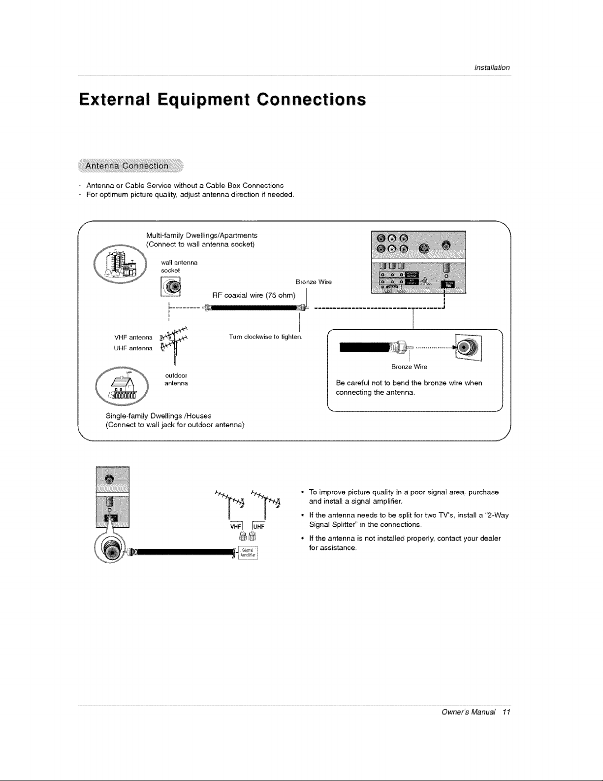
Antenna or Cabte Service without a Cable Box Connections
o For optimum picture quality, adjust antenna direction ff needed.
Mufti-family Dweliings/Apart_nts
(Connect to wall antenna socket)
Ins_llation
I
VHF antenna
UHF anter_r_
outdoor
antenna
Single-family Dwellings/Houses
(Connect to walt jack for outdoor antenna)
l ........ J
B_onze Wire
careful not to bend the bronze wire when
conn_ing the antenna.
• To improve picture quali_y' in a poor signal area, purchase
and inst_l a signal _p_ifier.
- if the antenna needs to be split for two TV's, install a "2-Way
SignaJ Splitter'' in the connections,
° if the antenna is not installed properly, con_ct your dealer
for assistance
Owner_ Manual 11
installation
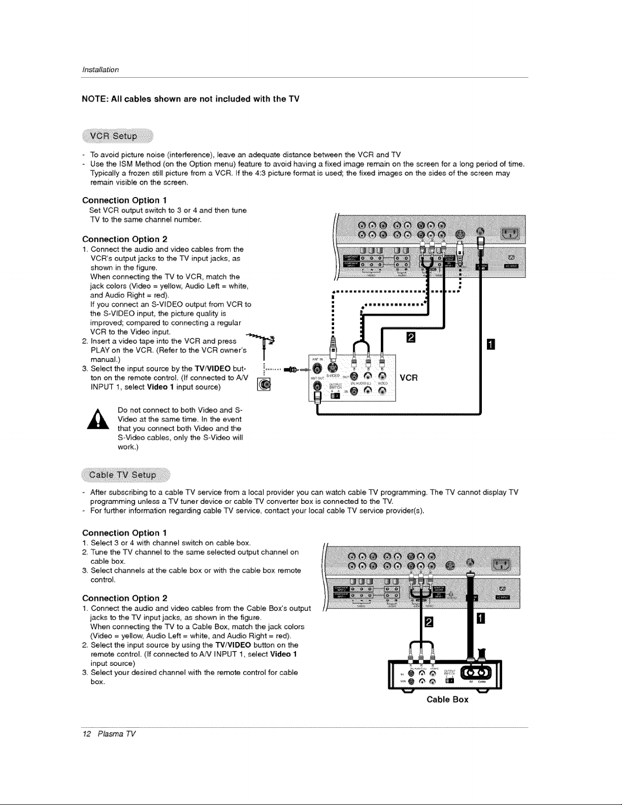
NOTE: All cables shown are not included with the TV
- To avoid picture noise (interfetence)_ _eave an adequate distance between the VCR and TV
Use the ISM Method (on the Option menu) feature to avoid having a fixed image remain on the _reen for a _ong pedod of t_me,
Typically a frozen stiB picture from a VCR if the 4:3 picture format is used the fixed images on the sides of the screen may
remain visible on the screen,
Connection Option 1
Set VCR output switch to 3 or 4 and then tune
TV to the same channel humor,
Connection Option 2
1, Connect the audio and video cables from the
VCR's output: jacks to the 3_# input jacks, as
shown in the figure,
When connecting the TV to VCR, match the
jack colors (Vi_o = yellow, Audio Left = white,
and Audio Right = red),
If you conn_ an S-WDEO output from VCR to
the S-WDEO input_ the picture quality is
improved; compared to connecting a regular
VCR to the Video input
2, Insert a video tape into the VCR and press .....
PLAY on the VCR (Refer to the VCR owner's T
manual,)
3, Select the input souroe by the TViVIDEO but- i......
ton on the remote control (If connected to A._"
INPUT 1_ select Vid_eo 1 input source)
/
|
Do not connect to both Vi_o and S-
Video at the same time. }n the event
that you connect both Video and the
SVi_o cables, only the SVideo wil_
work.)
- After subscribing to a cable TV service from a [_al provider you can watch cable q2¢ programming. The TV cannot display TV
programming unless a TV tuner device or cable TV converter box is connected to the TV.
- For fu_er information regarding cable TV service, contact your local c_le TV service provider(s),,
Connection Option 1
1, Select 3 or 4 with channef switch on cable box_
2, Tune the TV channet to the same selected output channe} on
cable box_
3 Select channets at the cabte box or with the cable box remote
control
Connection Option 2
1. Connect the audio and vi_o cabies from the Cabie Box's output
jacks to the TV input _acks, as shown in the figure.
When connecting the TV to a Cable Box, m_ch the jack colors
(Video = yeBow_ Audio Left = white, and Audio Right = red).
2. Select the input source by using the W/VIDEO button on the
remote control. (If connected to AA/INPUT 1, select Video 1
input source)
3. Select your desired channel with the remote control for cable
box.
Cable Box
il
12 Plasma TV
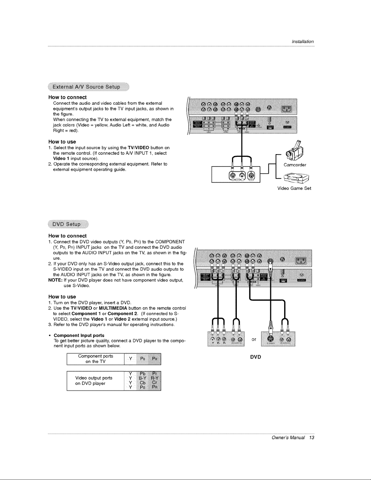
How to connect
Connect the audio and video cab[es from the external
equipment's output jacks to the P,./input jacks, as shown in
the figure.
When coRRecting the TV to external equipment, match the
jack colors (Video = yetlow, Audio Left = Site, _d Audio
Right = red).
How to use
1. Select the input source by using the TV/VlDEO button on
the remote control (if connected to _ iNPUT 1, select
Video 1 input source).
2, Operate the corresponding extema_ equipment Refer to
extern_ equipment operating guide
Installation
Camcorder
Video Game Set
How to connect
1. Connect the DVD video outpul_s (Y, PB, PR) to the COMPONENT
(Y, P& PR) iNPUT jacks on the TV and connect the DVD audio
ob_tputs to the AUDIO iNPUT jacks on the TV, as shown in the fig-
ure.
2. If your DVD only has an S-Video output jack, connect this to the
S-ViDEO input on the TV and connect the DVD audio outputs to
the AUDIO INPUT jacks on the TVl as shown in the figure.
NOTE: ff your DVD pmayer d_s not have component video output,
use SWideo.
HOW tO U_
1, Turn on the DVD player, insert a DVD_
2_ Use the TViVIDEO or MULTIMEDIA button on the remote control
to select Component I or Component 2, (if connected to S*
VIDEO, select the Video I or Video 2 external input source.)
& Refer to the DVD p_ayer's manua_ for operating instructions,
• Component Input po_s
To _t better picture quality, connect a DVD player to the compo-
nent input po_ as shown betow
Component po rt_s
on the TV
Video output ports
on DVD player
or
DVD
Owner's Manual 13
ir_ta_tion
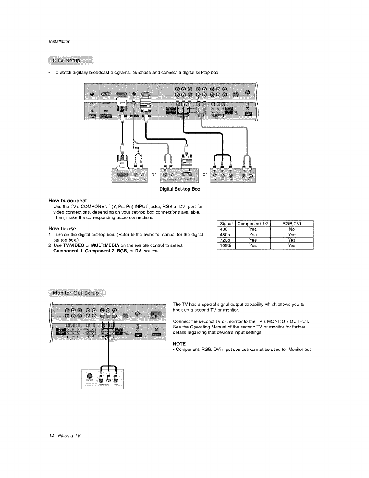
To watch digitally broadcast programs, purchase and connect a digffal set4op box.
::: o r
or
Digital Set4op Box
How to conn_t
Use the TV's COMPONENT (Y, PE_,PR) _NPUTjacks, RGB or DVI portfor
vi_o connections, depending on your set-top box connections avai_ab_e_
Then, make the corresponding audio connections,
How to use
1. Turn on the di@tat sef4op box. (Refer to the owner's manual for the digitaq
set4op _x.)
2. Use TViV|DEO or MULTIMEDIA on the remote control to select
Com_nent 1, Component 2, RGB, or DVI source.
The TV has a speciaJ signal output capabilit_y which allows you to
hook up a second TV or monitor,
Conne_ the second TV or monitor to _e TV's MONITOR OUTPUT.
See the Operating Manual of the second TV or _nitor for fu_er
details regarding that _vice's input settings.
NOTE
- Componenf, RGB, DVt input sources cannot be used for Monitor out,
480i Yes No
_££ Yes Yes
72op Yes Yes
1080i Yes Yes
14 Plasma TV
 Loading...