

LG RU-42PX10, RU-50PX10C, RU-42PX11C, RU-50PX10, RU-42PX11 Owner's Manual
...
PLASMA TV
OWNER’S MANUAL
Please read this manual carefully and completely before
operating your TV.
Retain this manual for future reference.
Record model number and serial number of the TV in the
spaces provided below.
See the label attached on the back cover and relate this
information to your dealer if you require service.
Model Number :
Serial Number :
MODELS: RU-42PX10/10C/11/11C
RU-50PX10/10C/11/11C
Internet Home Page : http://www.lg.ca
2 Plasma TV
Warning/Caution
WARNING/CAUTION:
TO REDUCE THE RISK OF ELECTRIC SHOCK DO NOT REMOVE COVER (OR BACK). NO USER
SERVICEABLE PARTS INSIDE. REFER TO QUALIFIED SERVICE PERSONNEL.
The lightning flash with arrowhead symbol, within an equilateral triangle, is intended to alert the user to
the presence of uninsulated “dangerous voltage” within the product’s enclosure that may be of sufficient magnitude to constitute a risk of electric shock to persons.
The exclamation point within an equilateral triangle is intended to alert the user to the presence of
important operating and maintenance (servicing) instructions in the literature accompanying the appliance.
WARNING/CAUTION:
TO PREVENT FIRE OR SHOCK HAZARDS, DO NOT EXPOSE THIS PRODUCT TO RAIN OR MOISTURE.
FCC NOTICE
• A Class B digital device
This equipment has been tested and found to comply with the limits for a Class B digital device, pursuant to Part
15 of the FCC Rules. These limits are designed to provide reasonable protection against harmful interference in
a residential installation. This equipment generates, uses and can radiate radio frequency energy and, if not
installed and used in accordance with the instructions, may cause harmful interference to radio communications.
However, there is no guarantee that interference will not occur in a particular installation. If this equipment does
cause harmful interference to radio or television reception, which can be determined by turning the equipment off
and on, the user is encouraged to try to correct the interference by one or more of the following measures:
- Reorient or relocate the receiving antenna.
- Increase the separation between the equipment and receiver.
- Connect the equipment into an outlet on a circuit different from that to which the receiver is connected.
- Consult the dealer or an experienced radio/TV technician for help.
• Any changes or modifications not expressly approved by the party responsible for compliance could void the user’s authority to operate the equipment.
CAUTION:
Do not attempt to modify this product in any way without written authorization from LG Electronics. Unauthorized modification could void the user’s authority to operate this product.
WARNING
RISK OF ELECTRIC SHOCK
DO NOT OPEN
/CAUTION
WARNING/CAUTION
TO REDUCE THE RISK OF FIRE AND ELECTRIC SHOCK, DO NOT EXPOSE THIS PRODUCT TO
RAIN OR MOISTURE.
W
W
arning/Caution
arning/Caution

Owner’s Manual 3
Safety Instructions
IMPORTANT SAFETY INSTRUCTIONS
Important safety instructions shall be provided with each apparatus. This information shall be given in a separate booklet
or sheet, or be located before any operating instructions in an instruction for installation for use and supplied with the apparatus.
This information shall be given in a language acceptable to the country where the apparatus is intended to be used.
The important safety instructions shall be entitled “Important Safety Instructions”. The following safety instructions shall be
included where applicable, and, when used, shall be verbatim as follows. Additional safety information may be included by
adding statements after the end of the following safety instruction list. At the manufacturer’s option, a picture or drawing that
illustrates the intent of a specific safety instruction may be placed immediately adjacent to that safety instruction :
1. Read these instructions.
2. Keep these instructions.
3. Heed all warnings.
4. Follow all instructions.
5. Do not use this apparatus near water.
6. Clean only with dry cloth.
7. Do not block any ventilation openings. Install in accordance with the manufacturer’s instructions.
8. Do not install near any heat sources such as radiators, heat registers, stoves, or other apparatus (including ampli-
fiers)that produce heat.
9. Do not defeat the safety purpose of the polarized or grounding-type plug. A polarized plug has two blades with
one wider than the other. A grounding type plug has two blades and a third grounding prong, The wide blade or the
third prong are provided for your safety. If the provided plug does not fit into your outlet, consult an electrician for
replacement of the obsolete outlet.
10. Protect the power cord from being walked on or pinched particularly at plugs, convenience receptacles, and the
point where they exit from the apparatus.
11. Only use attachments/accessories specified by the manufacturer.
12. Use only with the cart, stand, tripod, bracket, or table specified by the manufacturer, or sold with the apparatus.
When a cart is used, use caution when moving the cart/apparatus combination to avoid injury from tip-over.
PORTABLE CART WARNING
Safety Instructions
Safety Instructions

4 Plasma TV
Safety Instructions
13. Unplug this apparatus during lightning storms or when unused for long periods of time.
14. Refer all servicing to qualified service personnel. Servicing is required when the apparatus has been damaged
in any way, such as power-supply cord or plug is damaged, liquid has been spilled or objects have fallen into
the apparatus, the apparatus has exposed to rain or moisture, does not operate normally, or has been dropped.
15. CAUTION concerning the Power Cord :
Most appliances recommend they be placed upon a dedicated circuit; that
is, a single outlet circuit which powers only that appliance and has no
additional outlets or branch circuits. Check the specification page of
this owner's manual to be certain.
Do not overload wall outlets. Overloaded wall outlets, loose or damaged
wall outlets, extension cords, frayed power cords, or damaged or
cracked wire insulation are dangerous. Any of these conditions could
result in electric shock or fire. Periodically examine the cord of your
appliance, and if its appearance indicates damage or deterioration,
unplug it, discontinue use of the appliance, and have the cord replaced
with an exact replacement part by an authorized servicer.
Protect the power cord from physical or mechanical abuse, such as being
twisted, kinked, pinched, closed in a door, or walked upon. Pay
particular attention to plugs, wall outlets, and the point where the
cord exits the appliance.
16. Outdoor Use Marking :
WARNING - To Reduce The Risk Of Fire Or Electric Shock, Do Not Expose This Appliance To Rain Or Moisture.
17. Wet Location Marking :
Apparatus shall not be exposed to dripping or splashing and no objects filled with liquids, such as vases, shall
be placed on the apparatus.
Safety Instructions continued
Safety Instructions continued

Owner’s Manual 5
Introduction
Contents
Contents
Warning/Caution . . . . . . . . . . . . . . . . . . . . . . . . . . . . . . . .2
Safety Instructions . . . . . . . . . . . . . . . . . . . . . . . . . . . . .3~4
Introduction
Controls . . . . . . . . . . . . . . . . . . . . . . . . . . . . . . .7
Connection Options . . . . . . . . . . . . . . . . . . . . . .8
Remote Control Key Functions . . . . . . . . . . . . . .9
Installation
Installation Instruction . . . . . . . . . . . . . . . . . . . . . .10
Attaching the TV assembly to the wall . . . . . . . .10
External Equipment Connections . . . . . . . . . . . . .11
Antenna Connection . . . . . . . . . . . . . . . . . . . . .11
VCR Setup / Cable TV Setup . . . . . . . . . . . . . .12
External A/V Source Setup . . . . . . . . . . . . . . . .13
DVD Setup . . . . . . . . . . . . . . . . . . . . . . . . . . . .13
DTV Setup / Monitor Out Setup . . . . . . . . . . . . .14
PC Setup . . . . . . . . . . . . . . . . . . . . . . . . . . . . .15
Operation
Turning the TV On . . . . . . . . . . . . . . . . . . . . . . . .16
Menu Language Selection . . . . . . . . . . . . . . . . . .16
Channel Menu Options
Auto Program: Channel Search . . . . . . . . . . . . .17
Manual Program: Adding/Deleting Channels . . .17
Fine Tuning Adjustment . . . . . . . . . . . . . . . . . .17
Signal Reception Booster . . . . . . . . . . . . . . . . .18
Favorite Channels Setup . . . . . . . . . . . . . . . . . .18
Picture Menu Options
APC (Auto Picture Control) . . . . . . . . . . . . . . . .19
XD . . . . . . . . . . . . . . . . . . . . . . . . . . . . . . . . . .19
Color Temperature Control . . . . . . . . . . . . . . . .19
Fleshtone . . . . . . . . . . . . . . . . . . . . . . . . . . . . .20
sRGB . . . . . . . . . . . . . . . . . . . . . . . . . . . . . . . .20
Manual Picture Control (Off option) . . . . . . . . . .20
Sound Menu Options
DASP (Digital Auto Sound Processing) . . . . . . .21
BBE . . . . . . . . . . . . . . . . . . . . . . . . . . . . . . . . .21
AVL (Auto Volume Leveler) . . . . . . . . . . . . . . . .21
Manual Sound Control (Off option) . . . . . . . . . .22
Stereo/SAP Broadcasts Setup . . . . . . . . . . . . .22
Timer Menu Options
Auto Clock Setup . . . . . . . . . . . . . . . . . . . . . . .23
Manual Clock Setup . . . . . . . . . . . . . . . . . . . . .23
On/Off Timer Setup . . . . . . . . . . . . . . . . . . . . .23
Sleep Timer / Auto Off . . . . . . . . . . . . . . . . . . . .24
Special Menu Features
Key Lock . . . . . . . . . . . . . . . . . . . . . . . . . . . . .25
ISM (Image Sticking Minimization) Method . . . .25
Low Power . . . . . . . . . . . . . . . . . . . . . . . . . . . .26
XD Demo . . . . . . . . . . . . . . . . . . . . . . . . . . . . .26
Closed Captions . . . . . . . . . . . . . . . . . . . . . . . .27
Captions . . . . . . . . . . . . . . . . . . . . . . . . . . . . . .27
Caption/Text . . . . . . . . . . . . . . . . . . . . . . . . . . .27
Screen Menu Features
Auto Adjustment . . . . . . . . . . . . . . . . . . . . . . .28
Setting Picture Format . . . . . . . . . . . . . . . . . . .28
Screen Position . . . . . . . . . . . . . . . . . . . . . . . .28
Manual Configure . . . . . . . . . . . . . . . . . . . . . . .29
Setting VGA Mode . . . . . . . . . . . . . . . . . . . . . .29
Screen Adjustments . . . . . . . . . . . . . . . . . . . . .29
Cinema Mode Setup . . . . . . . . . . . . . . . . . . . . .29
Luminance Noise Reduction . . . . . . . . . . . . . . .30
Initializing (Reset to original factory value) . . . . .30
Split Zoom . . . . . . . . . . . . . . . . . . . . . . . . . . . .30
Lock Menu Options
Parental Lock Setup . . . . . . . . . . . . . . . . . . . . .31
PIP (Picture-In-Picture)/Double Window Feature
Watching PIP/Double Window . . . . . . . . . . . . ..32
Swapping the PIP/Double Window . . . . . . . . . .32
TV Program selection for PIP . . . . . . . . . . . . . .32
Selecting an Input Signal Source for PIP/Double Window .32
Moving the PIP . . . . . . . . . . . . . . . . . . . . . . . . .32
PIP Size . . . . . . . . . . . . . . . . . . . . . . . . . . . . . .32
PIP Transparency . . . . . . . . . . . . . . . . . . . . . . .32
External Control Device Setup . . . . . . . . . . . . . . . .33~38
IR Codes . . . . . . . . . . . . . . . . . . . . . . . . . . . . . . . .39~40
Programming the Remote . . . . . . . . . . . . . . . . . . . . . .41
Programming Codes . . . . . . . . . . . . . . . . . . . . . . .42~43
Troubleshooting Checklist . . . . . . . . . . . . . . . . . . . . . .44
Maintenance . . . . . . . . . . . . . . . . . . . . . . . . . . . . . . . . .45
Product Specifications . . . . . . . . . . . . . . . . . . . . . . . . .46
Setup and Operation Checklist
Setup and Operation Checklist
Setup and Operation Checklist
(See pages 11~15 for available connection and operational setup options.)
1. Unpack TV and all accessories.
2. Connect all external video and audio equipment.
see pages 12 ~ 14.
3 Install batteries in remote control.
See page 9.
4. Turn TV on.
See page 16.
5. Turn video source equipment on.
6. Select viewing source for TV.
See page 9.
7. Fine-tune source image and sound to your personal preference or as required by source.
See pages 19 ~ 22.
8. Additional features set up
See Contents above.

6 Plasma TV
Introduction
Introduction
Introduction
What is a Plasma Display Panel (PDP)?
A plasma display panel is the latest display technology. It is currently the best way to achieve flat panel displays with excellent
image quality and large screen sizes, that are easily viewable. The PDP can be thought of as a descendant of the neon lamp and
it can be also be viewed as a series of fluorescent lamps.
How does it work?
PDP is an array of cells, known as pixels, which are comprised of 3 sub pixels, corresponding to the colors red, green, and blue.
Gas in a plasma state is used to react with phosphors in each sub-pixel to produce colored light (red, green, or blue). These phosphors are the same types used in Cathode Ray Tube (CRT) devices such as televisions and common computer monitors.
You get the rich, dynamic colors that you expect. Each sub-pixel is individually controlled by advanced electronics to produce over
16 million different colors. All of this means that you get perfect images that are easily viewable in a display that is less than 5
inches thick.
160° - Wide angle range of vision
Your flat panel plasma screen offers an exceptionally broad viewing angle -- over 160 degrees. This means that the display is
clear and visible to viewers anywhere in the room who can see the screen.
Wide Screen
The screen of the Plasma Display is so wide that your viewing experience is as if you are in a theater.
Multimedia
Connect your plasma display to a PC and you can use it for conferencing, games, and Internet browsing. The Picture-in-Picture
feature allows you to view your PC and video images simultaneously.
Versatile
The light weight and thin size makes it easy to install your plasma display in a variety of locations where conventional TVs will not
fit.
The PDP Manufacturing Process: a few minute colored dots may be present on the PDP screen
The PDP (Plasma Display Panel), which is the display device of this product is composed of 0.9 to 2.2 million cells. A few cell
defects will normally occur in the PDP manufacturing process. Several tiny, minute colored dots visible on the screen should be
acceptable. This also occurs in other PDP manufacturers' products. The tiny dots appearing does not mean that this PDP is defective. Thus a few cell defects are not sufficient cause for the PDP to be exchanged or returned. Our production technology minimizes these cell defects during the manufacture and operation of this product.
Cooling Fan Noise (RU-50PX10/10C/11/11C only)
In the same way that a fan is used in a PC computer to keep the CPU (Central Processing Unit) cool, the PDP is equipped with
cooling fans to cool the Monitor and improve its reliability. Therefore, a certain level of noise could occur while the fans are operating and cooling the PDP.
The fan noise doesn't have any negative effect on the PDP's efficiency or reliability. The noise from these fans is normal during the
operation of this product. We hope you understand that a certain level of noise from the cooling fans is acceptable and is not sufficient cause for the PDP to be exchanged or returned.
Owner’s Manual 7
Introduction
Controls
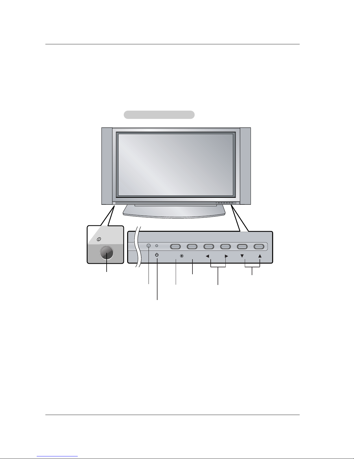
Controls
ON/OFF
TV/VIDEO
MENU
VOL CH
ON/OFF Button
- This is a simplified representation of front panel.
Here shown may be somewhat different from your TV.
- This manual explains the features available on the RU-42PX10 series TVs.
Front Panel Controls
Front Panel Controls
Remote Control Sensor
VOLUME (
F,G) Buttons
Power Standby Indicator
Illuminates red in standby mode,
Illuminates green when the TV is
turned on.
CHANNEL (E, D) Buttons
MENU Button
TV/VIDEO Button
8 Plasma TV
Introduction
Connection Options
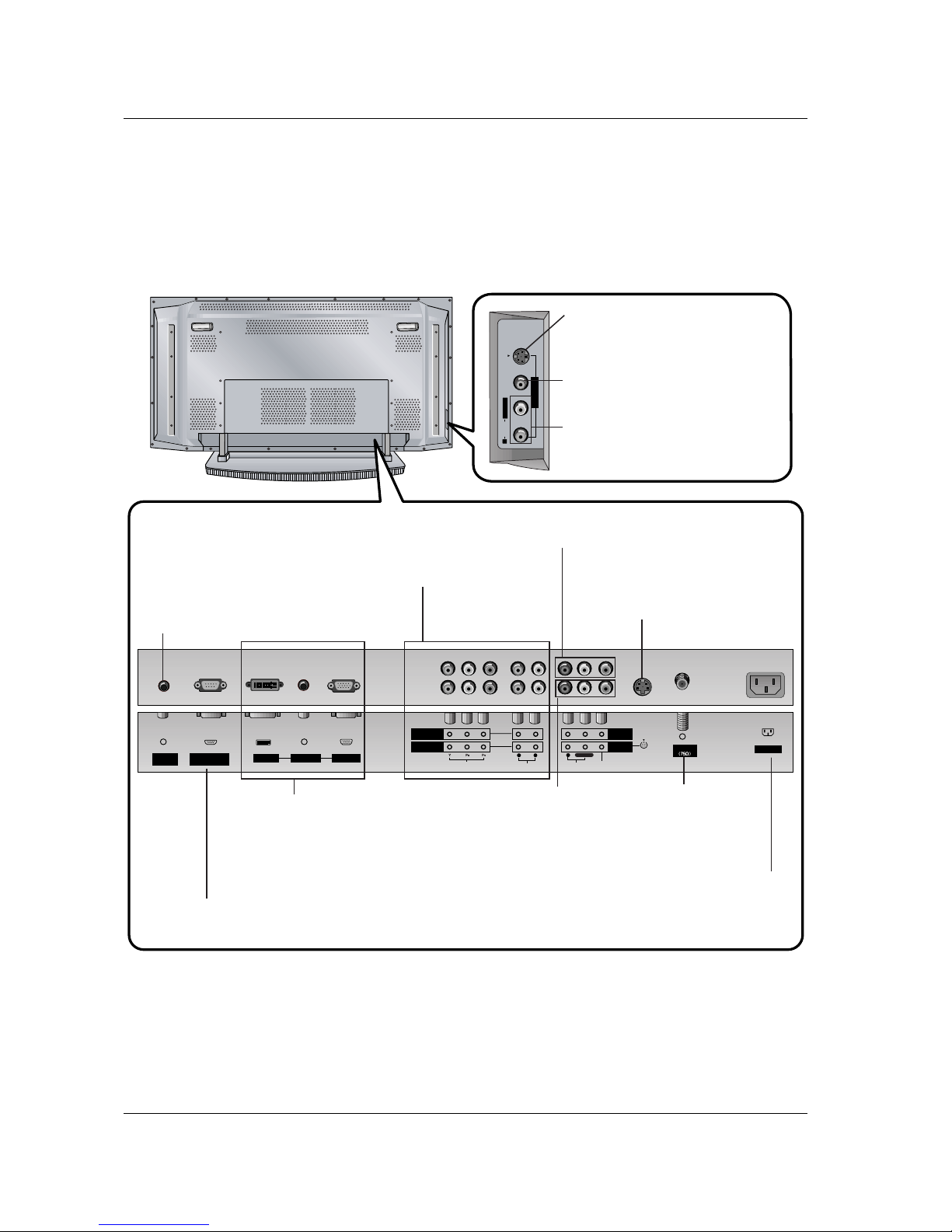
Connection Options
RGB INPUT
Antenna
AUDIO INPUT
DVI INPUT
S-VIDEO
REMOTE
CONTROL
AC INPUT
AUDIOVIDEO
COMPONENT
INPUT 2
COMPONENT
INPUT 1
MONITOR
OUTPUT
A/V
INPUT 1
AUDIO VIDEO
RS-232C INPUT
(CONTROL/SERVICE)
R
S-VIDEO VIDEO
L / MONO
AUDIO
A/V INPUT2
R
L
R
L/MONO
Antenna Input
Connect cable or antenna
signals to the TV, either
directly or through your
cable box.
RGB Input/Audio Input/DVI Input
Connect the monitor output connector from a
PC to the appropriate input port. If you want to
use RGB/DVI audio, we strongly recommend
that you use the cable that has a core, or the
EMI filter core along with separate cable.
Audio/Video Input 1
Connect audio/video out-
put from an external
device to these jacks.
DVD/DTV Input (Component 1-2)
Connect a component video/audio
device to these jacks.
Monitor Output
Connect a second TV or Monitor.
Remote Control Port
Connect your wired
remote control here.
S-Video Input
Connect S-Video out from an S-VIDEO
device to the S-VIDEO input.
Power Cord Socket
This TV operates on AC power. The voltage is indicated
on the Specifications page. Never attempt to operate
the TV on DC power.
RS-232C INPUT (CONTROL/SERVICE) PORT
Connect to the RS-232C port on a PC.
S-VIDEO Input
A connection available to provide better
picture quality than the video input.
VIDEO Input
Connects the video signal from a video
device.
AUDIO Input
Use to connect to hear stereo sound
from an external device.
Owner’s Manual 9
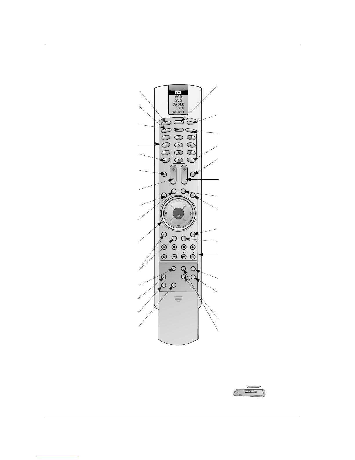
Introduction
- When using the remote control, aim it at the remote control sensor on the TV.
TV/VIDEO
M
U
L
T
IM
E
D
IA
MODE
A
R
C
APC
VOL CH
MENU
PIP/DW
CAPTION
EXIT
PIP CH-
PIP CH+ SWAP
PIP INPUT
PLAY PAUSE STOP RECORD
WIN.SIZE
WIN.POSITION
SLEEP
A.PROG
ENTER
MTS
MEMORY/ERASE
SPLIT ZOOM
REW FF SKIP
REVIEW
LIG
H
T
POW
ER
F
C
R
MUTE
DASP
HD
TV/VIDEO
Selects: TV, Video1-2, Component 1-2,
RGB, and DVI input sources.
MULTIMEDIA
Selects: Component 1-2, RGB, and
DVI input sources.
ARC
Changes the aspect ratio.
NUMBER buttons
FCR
Use to scroll the Surf channel list.
APC
Adjusts the factory preset picture according
to the room.
VCR/DVD BUTTONS
Control some video cassette recorders or
DVD player ("RECORD" button is not available for DVD player).
CAPTION
Selects CAPTION mode.
MODE
Selects the remote operating mode: TV,
VCR, DVD, CABLE, HDSTB or AUDIO.
Select other operating modes, for the
remote to operate external devices.
POWER
Turns your TV or any other programmed
equipment on or off, depending on mode.
MUTE
Switches the sound on or off.
DASP
Selects the sound appropriate for the program's character.
EXIT
Clears all on-screen displays and returns
to TV viewing from any menu.
REVIEW
Tunes to the last channel viewed.
THUMBSTICK (Up/Down/Left/Right/ENTER)
Allows you to navigate the on-screen
menus and adjust the system settings to
your preference.
CHANNEL UP/DOWN
Selects available channels found
with Auto program.
PIP INPUT
Selects the input source for the sub picture.
SWAP
Exchanges the sub/main images.
VOLUME UP/DOWN
Increases/decreases the sound level.
PIP/DW
Switches between PIP, and
Double Window modes.
PIPCH-/PIPCH+
Changes to next lower/higher PIP channel.
MENU
Brings up the main menu to the screen.
MTS
Selects the MTS sound: Mono, Stereo, or
SAP.
WIN.POSITION
Moves the sub picture.
SLEEP
Sets the sleep timer.
MEMORY/ERASE
Memorizes or erases selected channel.
A.PROG (AUTO PROGRAM)
Searches for available channels.
SPLIT ZOOM
Enlarges the picture.
Installing Batteries
• Open the battery compartment cover on the back side and install the batteries
matching correct polarity (+ with +, - with -).
• Install two 1.5V AA batteries. Don’t mix old or used batteries with new ones.
Replace cover.
Remote Control Key Functions
Remote Control Key Functions
WIN. SIZE
Adjusts the sub picture size.
LIGHT
Illuminates the remote control buttons.
10 Plasma TV
Installation
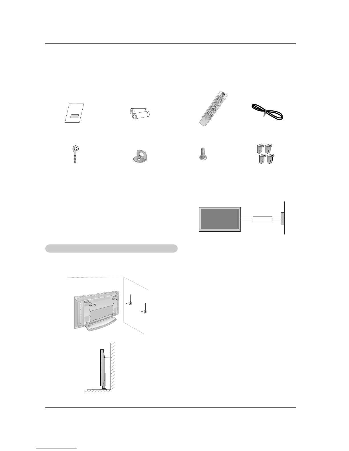
- Secure the set assembly by joining it to a wall by using the TV (or Eye Bolts)/Wall brackets.
- Here shown may be somewhat different from your TV.
Joinning the TV assembly to the wall to protect the set tumbling
Installation
Installation
Installation Instructions
Installation Instructions
GROUNDING
Ensure that you connect the grounding / earth wire to prevent possible
electric shock. If grounding methods are not possible, have a qualified
electrician install a separate circuit breaker. Do not try to ground the
unit by connecting it to telephone wires, lightening rods, or gas pipes.
Power
Supply
Short-circuit
Breaker
• If the set will be mounted on a desk top, insert the 2Eye Bolts (or 2-TV bracket bolts with 2-TV brackets)
and tighten them securely in the upper holes as
shown.
Install the wall brackets on the wall with bolts, (not
supplied with the product), as shown.
Match the height of the TV brackets (or Eye Bolts) and
the wall brackets.
Check to be sure the brackets are tightened securely.
• Secure the TV assembly to the wall with strong strings
or wire cables, (not supplied with the product), as
shown.
Ensure that the following accessories are included with your plasma display. If an accessory is missing, please contact the dealer
where you purchased the product.
Owner’s Manual
1.5V
1.5V
Batteries
Power Cord
TV
/V
IDEO
M
U
L
T
I
M
E
D
I
A
M
O
D
E
A
R
C
A
P
C
V
O
L
C
H
M
E
N
U
P
I
P
/
D
W
C
A
P
T
I
O
N
E
X
I
T
P
I
P
C
H
-
P
I
P
C
H
+
S
W
A
P
P
I
P
I
N
P
U
T
P
L
A
Y
P
A
U
S
E
S
T
O
P
R
E
C
O
R
D
W
I
N
.
S
I
Z
E
W
I
N
.
P
O
S
I
T
I
O
N
S
L
E
E
P
A
.
P
R
O
G
ENTER
M
T
S
M
E
M
O
R
Y
/
E
R
A
S
E
S
P
L
I
T
Z
O
O
M
R
E
W
F
F
S
K
I
P
R
E
V
I
E
W
L
I
G
H
T
P
O
W
E
R
F
CR
M
U
T
E
D
A
S
P
HD
Remote Control
2-TV brackets
2-Wall brackets
(option)
2-TV bracket bolts
(option)
2-Wall brackets (option)
2-Eye Bolts (option)
Owner’s Manual 11
Installation
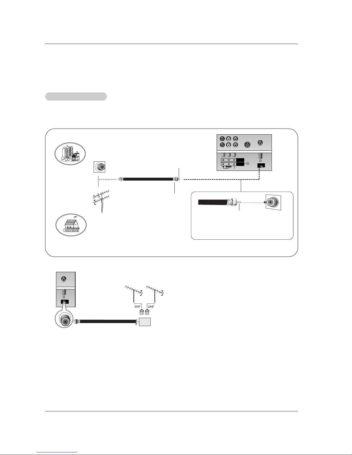
- Antenna or Cable Service without a Cable Box Connections
- For optimum picture quality, adjust antenna direction if needed.
External Equipment Connections
External Equipment Connections
Antenna Connection
Antenna Connection
• To improve picture quality in a poor signal area, purchase
and install a signal amplifier.
• If the antenna needs to be split for two TV’s, install a “2-Way
Signal Splitter” in the connections.
• If the antenna is not installed properly, contact your dealer
for assistance.
Antenna
Signal
Amplifier
Antenna
S-VIDEO
MONITOR
OUTPUT
A/V
INPUT 1
AUDIO VIDEO
R
L/MONO
Multi-family Dwellings/Apartments
(Connect to wall antenna socket)
Single-family Dwellings /Houses
(Connect to wall jack for outdoor antenna)
outdoor
antenna
wall antenna
socket
VHF antenna
UHF antenna
RF coaxial wire (75 ohm)
Bronze Wire
Turn clockwise to tighten.
Bronze Wire
Be careful not to bend the bronze wire when
connecting the antenna.
12 Plasma TV
Installation
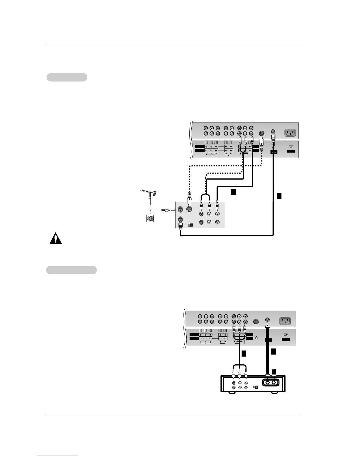
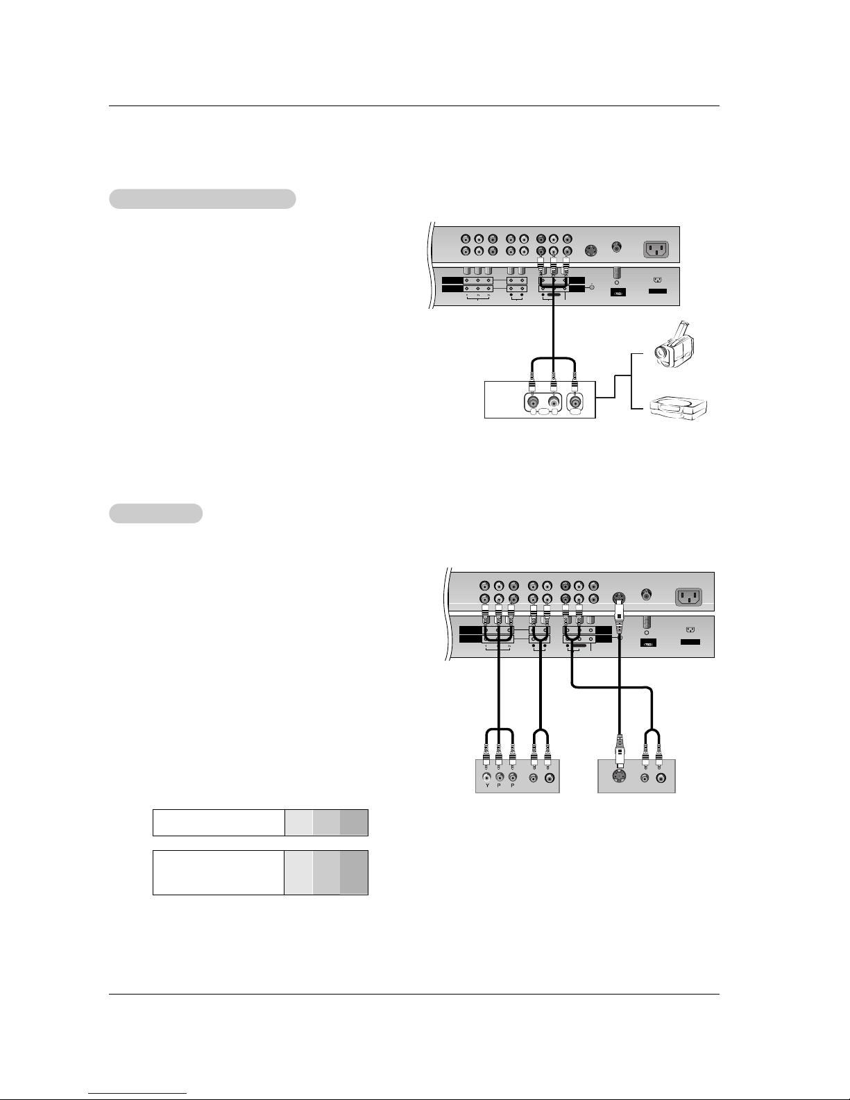
NOTE: All cables shown are not included with the TV
- To avoid picture noise (interference), leave an adequate distance between the VCR and TV
- Use the ISM Method (on the Option menu) feature to avoid having a fixed image remain on the screen for a long period of time.
Typically a frozen still picture from a VCR. If the 4:3 picture format is used; the fixed images on the sides of the screen may
remain visible on the screen.
Connection Option 1
Set VCR output switch to 3 or 4 and then tune
TV to the same channel number.
Connection Option 2
1. Connect the audio and video cables from the
VCR's output jacks to the TV input jacks, as
shown in the figure.
When connecting the TV to VCR, match the
jack colors (Video = yellow, Audio Left = white,
and Audio Right = red).
If you connect an S-VIDEO output from VCR to
the S-VIDEO input, the picture quality is
improved; compared to connecting a regular
VCR to the Video input.
2. Insert a video tape into the VCR and press
PLAY on the VCR. (Refer to the VCR owner’s
manual.)
3. Select the input source by the TV/VIDEO but-
ton on the remote control. (If connected to A/V
INPUT 1, select Video 1 input source)
Do not connect to both Video and SVideo at the same time. In the event
that you connect both Video and the
S-Video cables, only the S-Video will
work.)
VCR Setup
VCR Setup
Antenna
S-VIDEO
AC INPUT
AUDIOVIDEO
COMPONENT
INPUT 2
COMPONENT
INPUT 1
MONITOR
OUTPUT
A/V
INPUT 1
RL
AUDIO VIDEO
R L/MONO
S-VIDEO
OUT
IN
(R) AUDIO (L) VIDEO
34
OUTPUT
SWITCH
ANT OUT
ANT IN
- After subscribing to a cable TV service from a local provider you can watch cable TV programming. The TV cannot display TV
programming unless a TV tuner device or cable TV converter box is connected to the TV.
- For further information regarding cable TV service, contact your local cable TV service provider(s).
Connection Option 1
1. Select 3 or 4 with channel switch on cable box.
2. Tune the TV channel to the same selected output channel on
cable box.
3. Select channels at the cable box or with the cable box remote
control.
Connection Option 2
1. Connect the audio and video cables from the Cable Box's output
jacks to the TV input jacks, as shown in the figure.
When connecting the TV to a Cable Box, match the jack colors
(Video = yellow, Audio Left = white, and Audio Right = red).
2. Select the input source by using the TV/VIDEO button on the
remote control. (If connected to A/V INPUT 1, select Video 1
input source)
3. Select your desired channel with the remote control for cable
box.
Cable
Cable
TV Setup
TV Setup
Antenna
S-VIDEO
AC INPUT
AUDIOVIDEO
COMPONENT
INPUT 2
COMPONENT
INPUT 1
MONITOR
OUTPUT
A/V
INPUT 1
RL
AUDIO
VIDEO
R L/MONO
TV
VCR
RF Cable
(R) AUDIO (L) VIDEO
34
OUTPUT
SWITCH
VCR
Cable Box
1
2
1
2
Owner’s Manual 13
Installation
• Component Input ports
To get better picture quality, connect a DVD player to the component input ports as shown below.
How to connect
Connect the audio and video cables from the external
equipment's output jacks to the TV input jacks, as shown in
the figure.
When connecting the TV to external equipment, match the
jack colors (Video = yellow, Audio Left = white, and Audio
Right = red).
How to use
1. Select the input source by using the TV/VIDEO button on
the remote control. (If connected to A/V INPUT 1, select
Video 1 input source).
2. Operate the corresponding external equipment. Refer to
external equipment operating guide.
Component ports
on the TV
Y
PB
PR
Video output ports
on DVD player
Y
Y
Y
Y
Pb
B-Y
Cb
PB
Pr
R-Y
Cr
PR
How to connect
1. Connect the DVD video outputs (Y, P
B, P
R) to the COMPONENT
(Y, P
B, PR) INPUT jacks on the TV and connect the DVD audio
outputs to the AUDIO INPUT jacks on the TV, as shown in the figure.
2. If your DVD only has an S-Video output jack, connect this to the
S-VIDEO input on the TV and connect the DVD audio outputs to
the AUDIO INPUT jacks on the TV, as shown in the figure.
NOTE: If your DVD player does not have component video output,
use S-Video.
How to use
1. Turn on the DVD player, insert a DVD.
2. Use the TV/VIDEO or MULTIMEDIA button on the remote control
to select Component 1 or Component 2. (If connected to SVIDEO, select the Video 1 or Video 2 external input source.)
3. Refer to the DVD player's manual for operating instructions.
External
External
A/V Source Setup
A/V Source Setup
DVD Setup
DVD Setup
Antenna
S-VIDEO
AC INPUT
AUDIOVIDEO
COMPONENT
INPUT 2
COMPONENT
INPUT 1
MONITOR
OUTPUT
A/V
INPUT 1
RL
AUDIO
VIDEO
R L/MONO
RL
AUDIO VIDEO
Antenna
S-VIDEO
AC INPUT
AUDIOVIDEO
COMPONENT
INPUT 2
COMPONENT
INPUT 1
MONITOR
OUTPUT
A/V
INPUT 1
RL
AUDIO
VIDEO
R L/MONO
B
R
(R) AUDIO (L) (R) AUDIO (L)
S-VIDEO
DVD
or
Camcorder
Video Game Set
14 Plasma TV
Installation
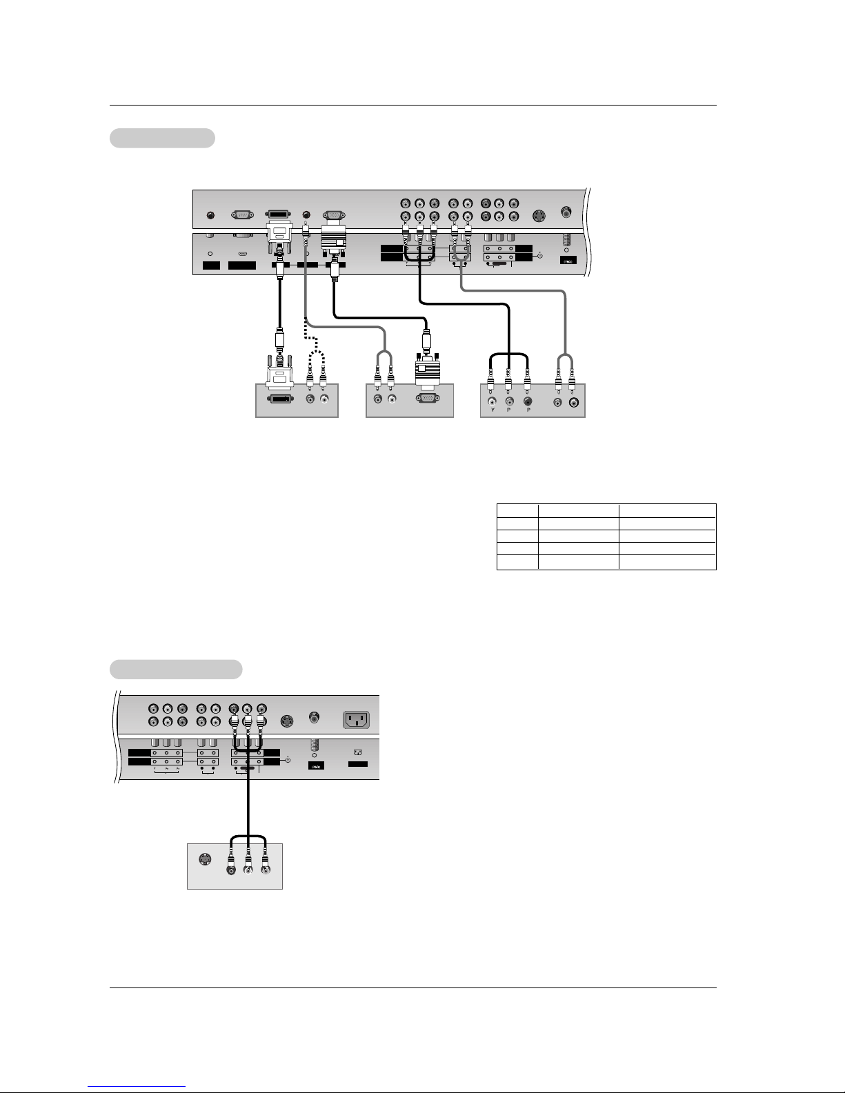
How to connect
Use the TV’s COMPONENT (Y, PB, PR) INPUT jacks, RGB or DVI port for
video connections, depending on your set-top box connections available.
Then, make the corresponding audio connections.
How to use
1. Turn on the digital set-top box. (Refer to the owner’s manual for the digital
set-top box.)
2. Use TV/VIDEO or MULTIMEDIA on the remote control to select
Component 1, Component 2, RGB, or DVI source.
- To watch digitally broadcast programs, purchase and connect a digital set-top box.
DTV Setup
DTV Setup
RGB INPUT
Antenna
AUDIO INPUT
DVI INPUT
S-VIDEO
REMOTE
CONTROL
AUDIOVIDEO
COMPONENT
INPUT 2
COMPONENT
INPUT 1
MONITOR
OUTPUT
A/V
INPUT 1
RL
AUDIO VIDEO
R
RS-232C INPUT
(CONTROL/SERVICE)
L/MONO
B
R
(R) AUDIO (L)
(R) AUDIO (L)
RGB-DTV OUTPUT
(R) AUDIO (L)
DVI-DTV OUTPUT
Digital Set-top Box
or
or
Signal
480i
480p
720p
1080i
Component 1/2
Yes
Yes
Yes
Yes
RGB,DVI
No
Yes
Yes
Yes
The TV has a special signal output capability which allows you to
hook up a second TV or monitor.
Connect the second TV or monitor to the TV’s MONITOR OUTPUT.
See the Operating Manual of the second TV or monitor for further
details regarding that device’s input settings.
NOTE
• Component, RGB, DVI input sources cannot be used for Monitor out.
Antenna
S-VIDEO
AC INPUT
AUDIOVIDEO
COMPONENT
INPUT 2
COMPONENT
INPUT 1
MONITOR
OUTPUT
A/V
INPUT 1
RL
AUDIO
VIDEO
R L/MONO
S-VIDEO
IN
(R) AUDIO (L) VIDEO
Monitor Out Setup
Monitor Out Setup
 Loading...