

LG RU-27FB30C Series, RU-27FB31C Series Service Manual
SERVICE MANUAL SERVICE MANUAL
Model Series:
Product Type:
Chassis:
Manual Part #:
Model Line:
Product Year:
Commercial Color TV
FC NARROW
3828VD0210A Rev A
H
2005
RU-27FB30C
RU-27FB31C
General Information/Remote Controls................................
Installer’s Menu ............................................................
Servicing/Trobleshooting ................................................
Model/Module Parts List .................................................
Exploded Views .............................................................
Schematics ...................................................................
Printed in U.S.A.
CONTENTS
1
2
3
4
5
6
Published by
Technical Publications
LG Electronics Corporation
P.O. Box 240007
Huntsville, Al 35824
Copyright February 2005 by LG Electronics Corporation ©
PRODUCT SAFETY SERVICING GUIDELINES FOR AUDIO-VIDEO PRODUCTS
A
IMPORTANT SAFETY NOTICE
This Manual was prepared for use only by properly trained audio-visual service
technicians. When servicing this product, under no circumstances should the
original design be modified or altered without permission from LG Electronics
Corporation. All components should be replaced only with types identical to
those in the original circuit and their physical location, wiring and lead dress
must conform to original layout upon completion of repairs.
Special components are also used to prevent x-radiation, shock and fire
hazard. These components are indicated by the letter “x” included in their
component designators and are required to maintain safe performance. LG
Electronics Corporation allows no deviations without prior approval. Circuit
diagrams may occasionally differ from the actual circuit used. This way,
implementation of the latest safety and performance improvement changes
into the set is not delayed until the new service literature is printed.
CAUTION: Do not attempt to modify this product in any way. Never perform
customized installations without manufacturer’s approval. Unauthorized modifications will not only void the warranty, but may lead to property damage or
user injury.
Service work should be performed only after you are thoroughly familiar with
these safety checks and servicing guidelines.
GRAPHIC SYMBOLS
The exclamation point within an equilateral triangle is intended
to alert the service personnel to important safety information in
the service literature.
The lightning flash with arrowhead symbol within an equilateral
triangle is intended to alert the service personnel to the presence
of non-insulated “dangerous voltage” that may be of sufficient
magnitude to constitute a risk of electric shock.
The pictorial representation of a fuse and its rating within an
equilateral triangle is intended to convey to the service personnel
the following fuse replacement caution notice:
CAUTION: FOR CONTINUED PROTECTION AGAINST RISK OF FIRE, REPLACE ALL FUSES WITH THE SAME TYPE AND RA TING AS MARKED NEAR
EACH FUSE.
SERVICE INFORMATION
While servicing, use an isolation transformer for protection from AC line
shock. After the original service problem has been corrected, make a check of
the following:
FIRE AND SHOCK HAZARD
1. Be sure that all components are positioned to avoid a possibility of
adjacent component shorts. This is especially important on items transported
to and from the repair shop.
2. Verify that all protective devices such as insulators, barriers, covers,
shields, strain reliefs, power supply cords, and other hardware have been
reinstalled per the original design. Be sure that the safety purpose of the
polarized line plug has not been defeated.
3. Soldering must be inspected to discover possible cold solder joints, solder
splashes, or sharp solder points. Be certain to remove all loose foreign
particles.
4. Check for physical evidence of damage or deterioration to parts and
components, for frayed leads or damaged insulation (including the AC cord),
and replace if necessary.
5. No lead or component should touch a receiving tube or a resistor rated at
1 watt or more. Lead tension around protruding metal surfaces must be
avoided.
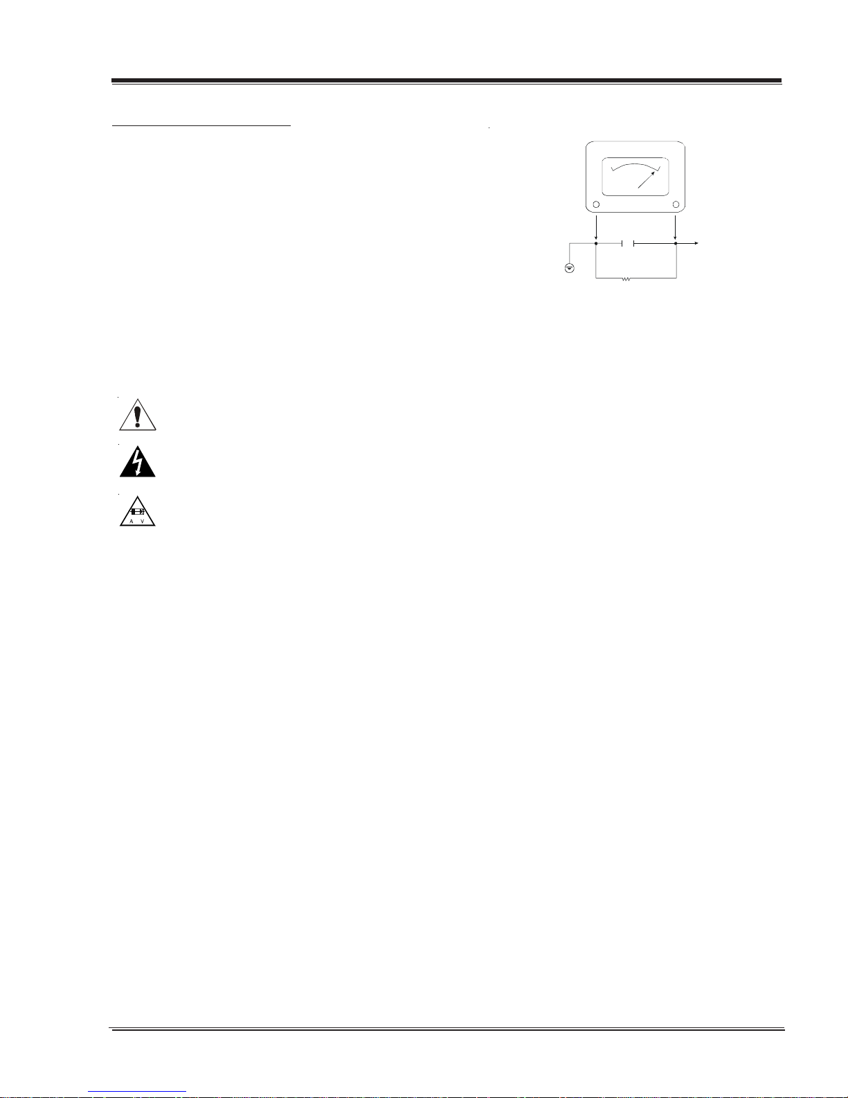
6. After re-assembly of the set, always perform an AC leakage test on all exposed
metallic parts of the cabinet (the channel selector knobs, antenna terminals,
handle and screws) to be sure that set is safe to operate without danger of
electrical shock. DO NO T USE A LINE ISOLA TI ON TRANSFORMER DURING THIS TEST .
Use an AC voltmeter having 5000 ohms per volt or more sensitivity in the
following manner: Conn ect a 1500 ohm, 10 watt r esistor, paralleled by .15 mfd
150V AC type capacitor between a known good earth ground (water pipe,
conduit, etc.) and the exposed metallic parts, one at a time. Measure the AC
voltage across the combination of 1500 ohm resistor and .15mfd capacitor.
Reverse the AC plug by using a non-polarized adaptor and repeat AC voltage
measurements for each exposed metallic part. Voltage measured must not
exceed 0.75 volts RMS. This corresponds to 0.5 milliamp AC. Any value
exceeding this limit constitutes a potential shock hazard and must be corrected immediately .
.C. Voltmet e r
Good Earth Ground
such as the Water
Pipe, Conduit, etc.
0.15uF
1500 OHM
10 WATT
Place this probe
on each exposed
metal part.
X-RADIATION
1. Be sure procedures and instructions to all service personnel cover the
subject of x-radiation. The only potential source of x-rays in current TV
receivers is the picture tube. However, this tube does not emit x-rays when
the HV is at the factory-specified level. The proper value is given in the
applicable schematic. Operation at higher voltages may cause a failure of the
picture tube or high-voltage supply and, under certain circumstances may
produce radiation in excess of desirable levels.
2. Only factory-specified CRT anode connectors must be used.
3. It is essential that the service personnel have available an accurate and
reliable high-voltage m eter .
4. When the high-voltage circuitry is operating properly, there is no possibility of an x-radiation problem. Every time a color chassis is serviced, the
brightness should be run up and down while monitoring the high voltage
with a meter, to be certain that the high voltage does not exceed the
specified value and that it is regulating correctly.
5. When troubleshooting and making test measurements in a product with a
problem of excessively high voltage, avoid being unnecessarily close to the
picture tube and the high voltage power supply. Do not operate the pr oduct
longer than necessary to locate the cause of excessive voltage.
6. Refer to HV, B+, and shutdown adjustment procedures described in the
appropriate schematics and diagrams (where used).
IMPLOSION
1. All direct view picture tubes are equipped with an integral implosion
protection system; take care to avoid damage during installation.
2. Use only the recommended factory replacement tubes.
TIPS ON PROPER INSTALLATION
1. Never install any receiver in a closed-in recess, cubbyhole, or closely fitting
shelf space over, or close to, a heat duct, or in the path of heated air flow.
2. Avoid conditions of high humidity such as: outdoor patio installations
where dew is a factor, near steam radiators where steam leakag e is a factor,
etc.
3. Avoid placement where draperies may obstruct venting. The customer
should also avoid the use of decorative scarves or other coverings that
might obstruct ventilation.
4. Wall- and shelf-mounted installations using a commercial mounting kit must
follow the factory-approved mounting instructions. A product mounted to
a shelf or platform must retain its original feet (or the equivalent thickness
in spacers) to provide adequate airflow across the bottom. Bolts or screws
used for fasteners must not touch any parts or wiring. Perform leakage tests
on customized installations.
5. Caution customers against mounting a product on a sloping shelf or in a
tilted position, unless the receiver is properly secured.
6. A product on a roll-about cart should be stable in its mounting to the cart.
Caution the customer on the hazards of trying to roll a cart with small
casters across thresholds or deep pile carpets.
7. Caution customers against using a cart or stand that has not been listed by
Underwriters Laboratories, Inc. for use with its specific model of television
receiver or generically approved for use with TVs of the same or larger screen
size.
8. Caution customers against using extension cords. Explain that a forest of
extensions, sprouting from a single outlet, can lead to disastrous consequences to home and family.
3828VD0210A FCN - SAFETY
i
PRODUCT SAFETY SERVICING GUIDELINES FOR AUDIO-VIDEO PRODUCTS
X-RADIATION
To prevent possible exposure to x-radiation caused by excessive CRT
anode voltage, the FC Narrow chassis incorporate a “High Voltage
Shutdown” circuit. This circuit senses the level of a flyback pulse
from the “Flyback Transformer” representative of the actual high
voltage on the CRT anode. When this level exceeds a predetermined
voltage, the circuit shuts down the TV set, preventing further generation of anode voltage.
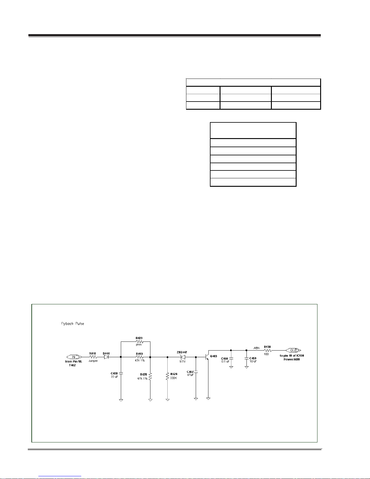
SHUTDOWN CIRCUIT OPERATION
The flyback pulse voltage from pin 10 of T402 (Flyback Transformer)
is peak detected (rectified) by the action of diode D444 and capacitor C450. This form a DC voltage appearing on C450 representative of the CRT anode voltage (HV) produced by T402. This voltage
is divided down by precision resistors R419, R423, R420 and R424.
This lower voltage appears on the zener diode ZDX447; when this
voltage exceeds by 0.7 Vdc the “zener voltage” Q403 enters in
saturation mode end then the HV shutdown occurs (pin 49 of
IC100).
CRT ANODE HIGH VOLTAGE MEASUREMENT PROCEDURE
Each CRT screen size has it’s own safe operating anode and
shutdown voltage. Critical safety component (designated with
an ‘X’ in the component designator) are designed to operate the
CRT at a safe operating anode voltage and provide proper shutdown thresholds. If replacement of any of these components
are deemed necessary, it is important to use original type LG
Electronics components. After replacement is made, confirm
proper anode voltage using the following procedure.
Measurement of the CRT anode voltage must be performed using a
high impedance-high voltage meter, with no raster on the screen,
and operating at nominal horizontal frequency, 15.75 Khz (NTSC
signal).
After discharging the CRT, connect a high impedance-high voltage
meter to the CRT anode. Turn the television ‘on’ and confirm a good
signal is being displayed. Reduce Brightness and Contrast settings
until the picture is well extinguished.
Observe the anode voltage meter reading and compare with the
table below for the proper CRT screen size. If the voltage reading
is higher than the maximum, verify circuit component values and
proper operation.
CRT Anode Voltage
CRT Screen Size Nominal Anode Voltage Max. Shutdown Voltage
(KV) (KV)
27" 30 ± 1.0 36
COMPONENTS WITH ANY INFLUENCE
IN HV INCREASE
Fly-B ack Transf ormer
Defle ction Yoke
CX404
CX406
CX405
ICX3751
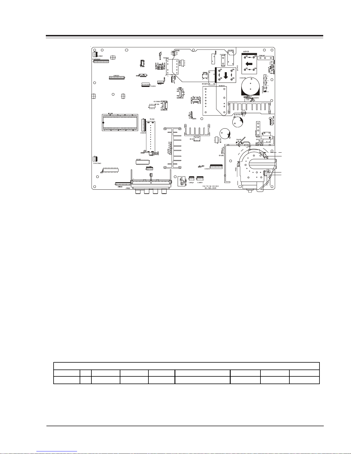
HV SHUTDOWN PROCEDURE.
·After discharging the CRT, connect a high impedance-high voltage meter to the CRT anode
·Remove jumper wire from RX3750.
·Connect a variable Resistor (1 MW) in location RX3750.
·Access Video Menu and adjust Brightness and Contrast controls
for minimum screen luminance (beam current to 0 mA).
·Wait until the Video Menu or display disappear.
·Increase (from zero) slowly the resistance value until shutdown
occurs.
·Measure High Voltage shutdown.
3828VD0210A FCN - SAFETY
ii

T ABLE OF CONTENTS
SECTION 1..............GENERAL INFO
PRODUCT SAFETY SERVICING GUIDELINES .............. i~ii
OVERVIEW............................................................1-1
Connections.................................................... 1-3
REMOTE INFO ........................................................1-4
SC652LG ................................................... 1-4
CLONE PROGRAMMER .............................................1-5
QUICKSET II PROGRAMMER ................................ 1-5
LEARN FROM TV............................................... 1-5
TEACH TO TV................................................... 1-5
SET CLONE CLOCK FROM TV ............................... 1-6
DISPLAY TV SETUP ........................................... 1-6
DISPLAY CLONE SETUP ..................................... 1-6
OPERATION NOTES ........................................... 1-6
USER MENUS ........................................................ 1-7
SETUP MENU................................................... 1-7
AUTOPROGRAM........................................... 1-7
CHANNEL LABELS ........................................... 1-7
CLOCK SET ...................................................... 1-8
TIMER ............................................................ 1-8
CAPTIONS....................................................... 1-8
TILT ............................................................... 1-8
DEGAUSS........................................................ 1-9
LANGUAGE ...................................................... 1-9
AUDIO MENU .................................................. 1-9
OVERVIEW .................................................... 1-10
ON SCREEN DISPLAYS..................................... 1-11
SECTION 4................MODEL PARTS
RU-27FB30C ...................................................... 4-1
SECTION 5....................DIAGRAMS
RU-27FB30C.................................................... 5-1
SECTION 6..................SCHEMATICS
Microprocessor................................................ 6-1
Audio ............................................................ 6-2
Power Supply .................................................. 6-3
Deflection ...................................................... 6-4
Til t................................................................ 6-5
Edge Card ...................................................... 6-6
MPI Card ........................................................ 6-7
Video Output .................................................. 6-8
Keyboard........................................................ 6-9
Ir Led Switch ................................................ 6-10
Front Jack .................................................... 6-11
PCB Layout Top ............................................. 6-12
2nd PCB Layout Top....................................... 6-13
SECTION 2..........INSTALLER MENU
INSTALLERS MENU.................................................2-1
INSTALLERS MENU ADJUSTMENTS ....................... 2-1
FACTORY MENU ............................................... 2-9
SECTION 3....................SERVICING
SERVICING............................................................3-1
GENERAL INFORMATION .................................... 3-1
SHUTDOWN CIRCUIT OPERATION ......................... 3-2
CRT ANODE ..................................................... 3-2
IF SERVICING .................................................. 3-3
G2 ADJUSTMENT .............................................. 3-3
FOCUS ADJUSTMENT......................................3-3
ADJUSTMENT OF RGB CUTOFF ............................ 3-4
SWITCHING PROCESS ........................................ 3-4
SENSING AND PRIORITIES...............................3-4
PURITY AND CONVERGENCE SETUP.....................3-5
TOC - 1 FCS-48SERIES -TOC
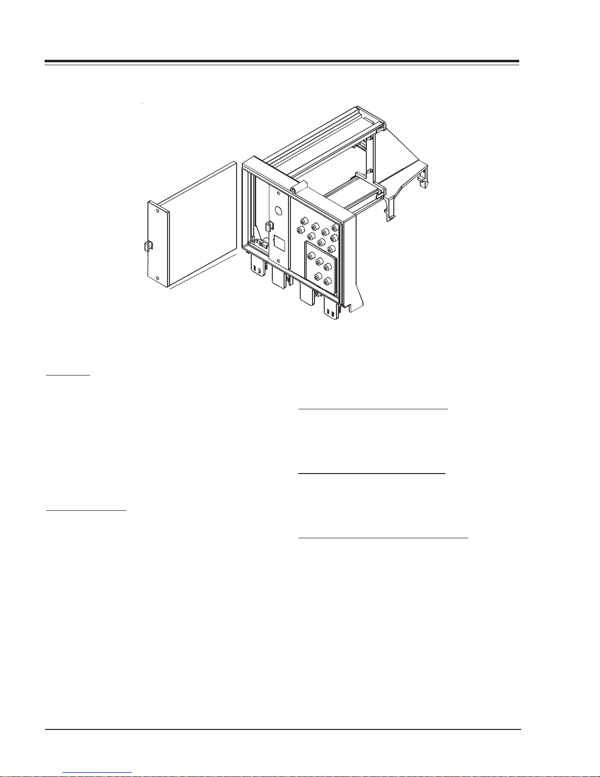
OVERVIEW
INTRODUCTION
This manual covers the FC Narrow Chassis Comercial Sets. This chassis has stereo, surround, MPI, and component video
ports.
IC100 - IF, micro, audio, video, sync and sweep drive processing. And it is tied directly to the keyboard and the
infrared detector.
IC101 - System memory.
IC301 - Vertical sweep amplifi er.
IC200 - Component Video switch.
ICX3612 - Stand by power supply regulator.
ICX3670 - Power supply. This is a switching type supply powered by a bridge rectifier circuit. At turn on, voltages for
the vertical and video output circuit are derived from the sweep circuit.
IC800 - Audio Amplifi er.
IC201 - Audio switch.
FCS Chassis Model Information
MODEL SCR FRONT JACKS REAR JACKS AUDIO EXTRA FEATURES REMOTE MICRO OP GUIDE
RU-27FB30C 27 4 12
Stereo MTS
SuperPort Slot, MPI Card 6710V00108B 0IMCRMN032A 3828VA0524A
3828VD0210A 1-1 FCN - OVERVIEW
OVERVIEW (continued)
INTERFACES
CAMPORT
This model has s-video, video and rigth/left audio input jacks, at the front of the receiver. These jacks can
be used to view video tapes from a VCR or Camcorder.
When the video cable is plugged into the jack. The TV
switches into the auxiliary mode. As long as the cables
are attached, the TV set will be locked in auxiliary mode.
Use of a remote control or buttons on the front of the
set will not permit switching into tuner mode until the
video cable is disconnected.
SUPERPORT - MPI
LG Commercial Product receivers are now being adapted
to interact with other equipment. Prime examples of
this can be found in Lodging and Health Care situations where the set is controlled from the main office.
All this is made possible by the new technology that is
being built into these receivers. The SuperPort and
Multiple Protocol Interface (MPI) jack and associated
circuitry allow remote control of the set.
MULTIPLE PROTOCOL INTERFACE
Television functions and features are controlled by the
communication of commands and status information
through a SuperPort by the MPI interface.
EBC (EDGE BOARD CONNECTOR)
Allows easy for removing/installing accessory modules
providing a rail mounted slide-through card. These cards
might contain one of the above features.
CONNECTION CENTER ON BACK OF TV
The connection on the back of the TV contains the
input and output interfaces.
3828VD0210A 1-2 FCN - OVERVIEW
OVERVIEW (continued)
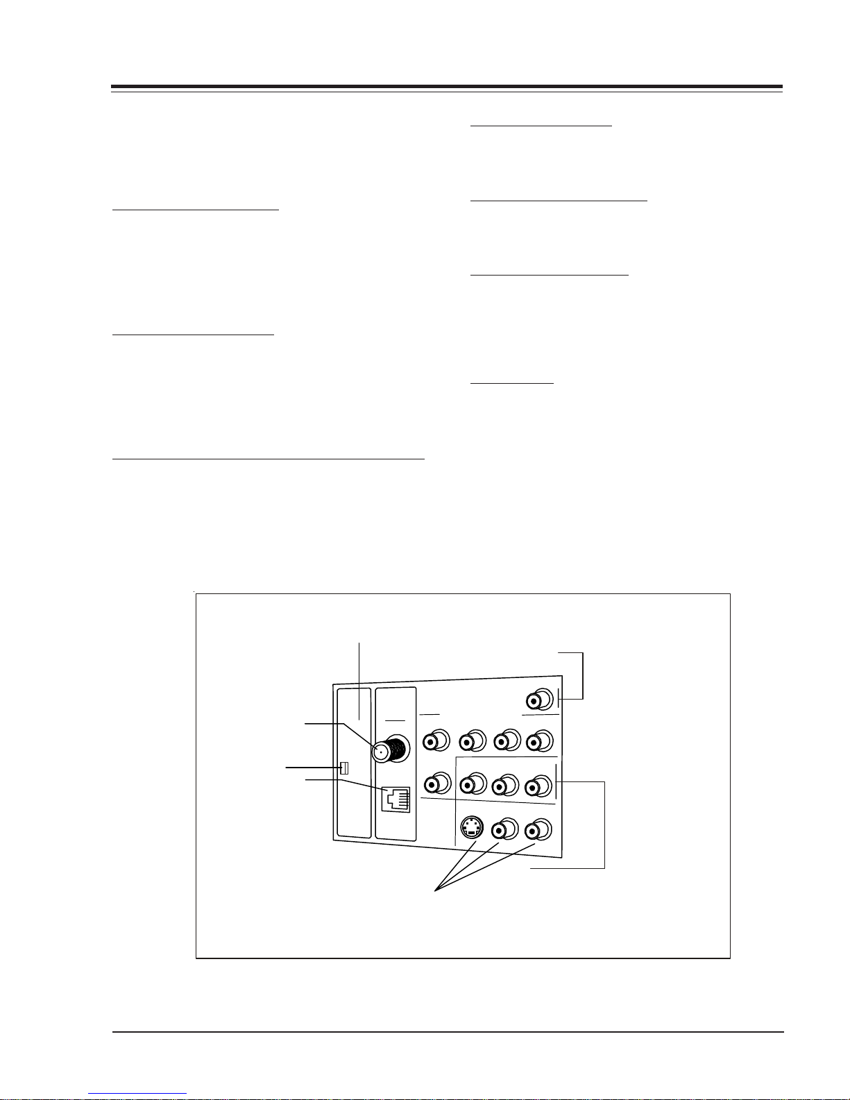
CONNECTION CENTER ON BACK OF TV
The connection center on the rear of the TV allows for
connection of the viewing source. The diagrams list the
use of each jack on the connection center.
1. ANTENNA/CABLE JACK
Use the jack for 75-ohm antenna-type signal connections to the TV. Attach antenna, cable TV line, or other
video equipment to jack. The input cable may come
from an outdoor or master antenna, cable TV line, cable
decoder box, or the RF output from a VCR.
2. SUPERPORT LOCATION
Provides for easy installation of local service provider
accessory module without removing the cabinet back.
Module is housed inside the TV cabinet and receives
operating power and all necessary interface signals
through internal connections.
3. MPI (MULTIPLE PROTOCOL INTERFACE) JACK
Standard RJ11 jack that provides interface with in-room
entertainment and video services. Also used with
installer’s programmer (page *-*) for programming other
TVs in the system with the same features as the master
TV.
4. COMPONENT INPUT
These jacks are for input connections to YPrPb (or YCrCb)
Video equipment.
5. VIDEO IN AND AUDIO IN
Use the Video and Audio In jacks for base band video
and audio input signals from a VCR or other signal source.
6. MATRIX SPEAKER OUT
Use this jack for connection of an 8-ohm extension
speaker to get television sound at a remote location.
The speaker in the TV remains active, while a monaural
audio output is heard from the remote speaker.
7. EBC KNOB
For handling/removal of EBC (Edge Board Card)
2
6
Matrix Out
Antenna
Super
Port
Cable
M.P.I.
1
7
3
Component Video Input
Pr
Pb
Y
Video In
S
V
-
i
e
d
o
4
I
n
R Audio L
R Audio In L
R
A
u
o
i
d
5
I
n
L
3828VD0210A 1-3 FCN - OVERVIEW
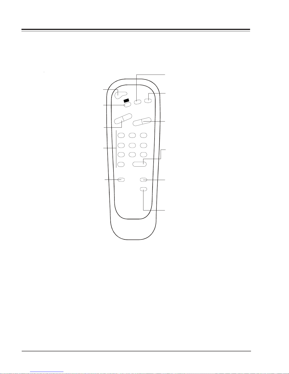
REMOTE CONTROL
FLASHBK (FLASHBACK)
Returns to the last channel viewed.
Turns TV On or Off
POWER
CC (CLOSED CAPTIONING)
Press to access
closed options.
Press ENTER to exit..
VOLUME DOWN/UP
Adjusts the sound level.
NUMBER KEYPAD
Select channels directly; ent er
channe l nu mbers and press
(SLEEP) TIMER
Press repeatedly to choose a
TV turn-off time up to 4-hours.
Use to set AM/PM on the
Alarm menu.
POWER
MUT
K
B
H
S
L
F
C
C
E
M
U
L
O
V
+
-
123
708
TIMER
Remote Control part number
L
E
N
N
A
H
C
+
-
546
9
ENTER
ALARM
CH PREVIEW
SC652LG
6710V00108B
E
MUTE
Turns sound Off and On, while the
picture remains.
CHANNEL (UP/DOWN)
Scroll th ro ugh available channels,
.
and the Video Channel (Audio/Video
source).
.
ENTER
Pres s t o view the
Channel/Time/Audio
display or t o r emove any on-screen
display or m enu.
ALARM
Pres s t o display menu, foll o w onscreen instructions to set a time for
the TV to turn itself on.
CHANNEL PREVIEW
Display s th e available TV ch annels,
gives the hotel guest access to the
Aux Channel and (if active) th e
Guest Par ental Control me nu. Aux
Channel al lows the guest to sel ect
the Video/Audio inputs. (Use the
Video/Audio jacks on the back of the
TV as the so ur ce of the picture an d
sound).
3828VD0210A 1-4 FCN - OVERVIEW
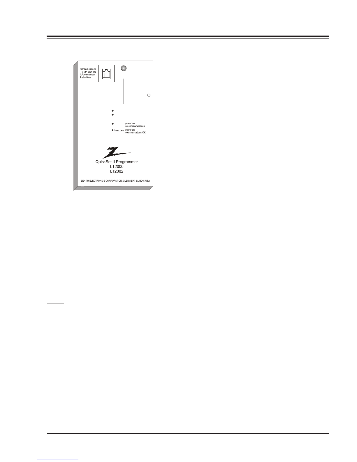
LT2000 & LT2002 CLONE PROGRAMMER
Status
Indicator
MPI
Reset
Color
battery OK
green
battery low
red
Blink pattern
slow
QUICKSET II PROGRAMMER
The Quickset II progr ammer L T2000 & L T2002allows custom setup and programming information to be quickly
copied from a master TV into multiple television sets.
Once learned from the master, setup data is retained in
the LT2002 for future use and recall.
When using the LT2002 operation will be easier if the
TV is connected to a good quality signal and is displaying a stable picture. To operate the LT2002 use the
indicated keys on an installer’s remote or user’s remote,
or the front panel keys on the TV receiver.
SETUP
Begin the programming process by setting up a master
TV set using one of the installer’s remotes or the MBR
remote. Follow the instructions in the operating guide
for the specific TV model. Remember to set all features
that will be customized including the channel scan list,
channel labels, and installers menu setups.
Next connect th e LT2002 to the master TV set using the
cable provided with the programmer. Connect the cable
between the MPI jack on the TV and the programmer.
The TV set automatically activates the programmer.
Once connected, check the “Status Indicator” LED on
the programmer. If the indicator is green and flashing
(a double-blink “heartbeat” pattern), proceed to the
next step.
Note: A slowly flashing green light indicates there is
a problem with communications between TV and
programmer. In this case, check for damaged
cable, poor contacts, or other connection
problems. If the status indicator is red, the
programmer batteries are low.
If communications are good, the sign-on screen will be
displayed on the TV screen as shown on the quick setup
instructions. If the intention is to set TV’s or
programmer’s real-time clocks, and not the clone clock
or TV clock time settings, then press a key to proceed
to main clone menu.
If a previously stored TV setup is in a particular clone
memory, it may be changed if desired by overwriting it
with a new setup. There is no need for a separated memory
clear operation. Setups stored in programmer memory
are nonvolatile and will be retained even after a battery
change.
LEARN FROM TV
Select “Learn From TV” then press ON/OFF, POWER, or
ENTER to begin learning process. Alternatively, use the
TV front panel CHANNEL UP or CHANNEL DOWN keys to
highlight choice. Press ON/OFF, POWER, or ENTER to
activate. The next screen will allow a choice of three
available memories to store this TV setup. Four different TV setups can be stored in the LT2002.
Using the On-screen menu, choose a memory or choose
to return to the main selection menu; Now press ON/
OFF, POWER or ENTER to activate your selection. The
next screen allows one last opportunity to check the
versions of TV and clone setups.
Press ON/OFF or POWER to activate learning cycle, or
press any other key to return to the selection menu to
make another choices.
Once a process has begun, the TV screen will display
“LEARNING IN PROGRESS”. Please wait for the pr ocess to
complete. When the TV screen displays “LEARNING COMPLETED”, press any key to end the learning process and
return to the clone selection menu.
TEACH TO TV
Select “TEACH TO TV”, and then press ON/OFF, POWER,
or ENTER to begin teaching process. Alternatively, use
the TV front panel CHANNEL UP or DOWN keys to highlight the ch oice, and then press ON/OFF, POWER, or ENTER to activate. The next screen displays a choice of
the three available memories that can be copied to the
TV. Select the desired memory number, and press ON/
OFF, POWER or ENTER to begin the teaching process.
Alternatively , use the TV fron t panel CHANNEL UP or DOWN
keys to highlight choice. Press ON/OFF, POWER, or ENTER to begin.
3828VD0210A 1-5 FCN - OVERVIEW

LT2000 & 2002 CLONE PROGRAMMER
Using the on-screen menu, select a memory or return to
the main selection m enu. Th en press ON/OFF, POWER, or
ENTER to activate the selection.
The next screen allows for one last opportunity to check
the versions of TV and clone setups. Press ON/OFF or
POWER to activate the teaching cycle, or any other key
to return to the selection menu to make other choices.
Once a process has begun, the TV screen will display the
“TEACHING IN PROGRESS” message. Please wait for the
process to complete. When the TV screen displays
“TEACHING COMPLETED”, press any key to end the teaching process and return to the clone selection menu.
SET CLONE CLOCK FROM TV
To set th e real-time clock in the L T2002 select “SET CLONE
FROM TV” and then press ON/OFF, POWER, or ENTER to
copy current TV time to the clock. Alternatively, use
the TV front panel CHANNEL UP or CHANNEL DOWN keys
to highlight the choice. Then press ON/OFF, POWER, or
ENTER to activate.
This process will return the L T2002 to th e sign-on screen
to display the clone and TV clock settings. Press a key
to go to the clone selection menu and perform other
functions, or simply disconnect if time setting was the
last task.
SET TV CLOCK FROM CLONE
To set the real time clock in the select “SET TV CLOCK
FROM CLONE” and then press ON/OFF , POWER or ENTER to
copy current LT2002 time to the TV clock.
Alternatively, use the TV front panel CHANNEL UP or
CHANNEL DOWN keys to highlight the choice. Then press
ON/OFF, POWER or ENTER to activate.
This process will return the L T2002 to th e sign-on screen
to display the clone and TV clock settings. Press a key
to go the clone selection menu and perform other functions, or simply disconnect if the time setting was the
last task.
DISPLAY TV SETUP
Select “DISPLAY TV SETUP”, and then press ON/OFF,
POWER, or ENTER to begin the teaching process. Alternatively , use the TV front pan el CHANNEL UP or CHANNEL
DOWN keys to highlight your choice. Then press ON/
OFF , POWER, or ENTER.
The TV screen will display the items in the service menu
setups. Use this function to quickly check a TV for correct setup. Press any key to clear display and return to
clone selection menu.
DISPLAY CLONE SETUP
Select “DISPLAY CLONE SETUP”, and then press ON/OFF,
POWER or ENTER to begin the teaching process. Alternatively , use the TV front pan el CHANNEL UP or CHANNEL
DOWN keys to highlight the choice, then press ON/OFF,
POWER or ENTER to begin.
The TV screen will display the memory selection menu.
Select the desired memory number, and then press ON/
OFF, POWER, or ENTER to display contents of the selected memory. Alternatively , use th e TV’s CHANNEL UP
or CHANNEL DOWN keys to highlight the choice, then
press ON/OFF, POWER or ENTER to begin.
The TV screen will display items in the service menu
setup. Use this function to quickly check contents of a
particular clone memory for correct setup. Press any key
to clear the display and return to the clone selection
menu.
OPERATION NOTES
Disconnect the LT2002 from the TV set when the desired task has been completed. Disconnecting the clone
automatically switches it off. The real time clock continues to run when the main circuits are switched off.
After replacing exhausted batteries, or if the programmer behaves strangely after a static shock, use a paper
clip or similar instrument inserted through the small
hole marked “RESET” to activate the internal reset switch
and restore normal operation. After reset, check the realtime clock setting. It may be necessary to reset the
clock from a TV programmed to the correct time.
The specific microprocessor used in any TV set may be
determined by activating the service menu. The microprocessor part number appears at the top of the screen
whit the service menu is activated. Processors before
the 221-01006 has limited screen display capability.
They cannot display entire screens as shown in the quick
setup instructions accompanying the LT2002 programmer. Use the printed menu illustrations on the quick
setup sheet as an aid to making programming choices.
3828VD0210A 1-6 FCN - OVERVIEW
USER MENUS
SETUP MENU
Press the Menu key on the Installer’s remote repeatedly
so that the SETUP MENU appears on the screen
SETUP MENU
AUTO PROGRAM
ADD/DEL/BLNK
CH. LABELS
SOURCE NAME
CLOCK SET
TIMER
CAPTIONS
TILT
DEGAUSS
LANGUAGE
TO PROGRAM
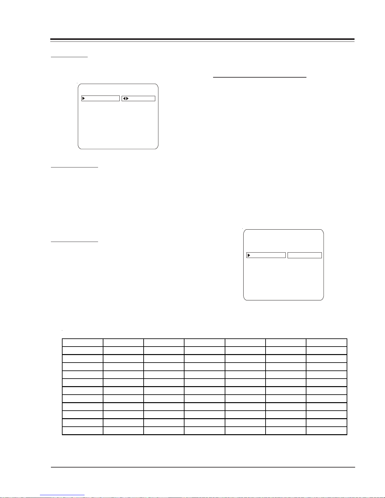
AUTO PROGRAM
Using the Up/Down arrows on the remote control, highlight AUTO PROGRAM on the screen. Then press Right/
Left Adjust arrow button to reach the AUTO PROGRAM
screen. Using the Up/Down arrows, choose either CABLE
TV or OFF-AIR ANTENNA. Press the Right or Left Adjust
arrows to being the Channel Search. The receiver searches
for available channels and stores them in memory for
user access.
ADD/DEL/BLNK
Press the Up Arrow repeatedly to highlight the ADD/
DEL/BLNK option. Use the remote to select a channel.
ADD/DELETE allows tailoring of the channel scan to eliminate unwanted channels and add desired channels that
were not stored during Auto Programming.
Use the number keypad and ENTER to add a deleted
channel. Using the Right/Left arrows, pick whether a
channel is Added, Deleted, or Blank.
When BLNK is selected, screen will be black while audio
continues.
Select any other channels to be changed, and when finished, press ENTER to close the menu.
CH LABELS (CHANNEL LABELS)
Press the MENU key on the remote so that the SETUP
MENU reappears. Use the Up Arrow to choose the CH
LABELS option. Pressing either the Right/Left arrow repeatedly, pick the label you want from the list of available selections shown in the chart. Select other channels, and when you are finished, press ENTER to remove
the menu.
You also have the option of creating 1 programmable
label having five characters each.
In order to edit a programmable channel label, it must
be selected or already present in the current channel,
pressing Volume Up/Down keys any digit can be selected and edited, with the Channel Up/Down keys the
blinking character can be edited, pressing the Volume
Up/Down key again can select another character and
also be edited. The channel label with be stored pressing Volume Up/Down keys until there is not any digit
blinking.
SETUP MENU
AUTO PROGRAM
ADD/DEL/BLNK
CH. LABELS CH 32 MYLAB
SOURCE NAME
CLOCK SET
TIMER
CAPTIONS
TILT
DEGAUSS
LANGUAGE
PRESS VOL UP/DN TO SELECT CHAR
A&E CMTV ESPN HSE NOS TBN VC
ABC CNBC ESP2 HSN PBS TELE V CR
ACTS CNN ET IC PLAY TLC VH-1
ADC COM EWTN INSP PTL TMC VISN
AMC CSPN FAM JCN QVC TNN VJN
BCC CSP2 FNN LIFE RDS TNT WB
BET CTN FOX MAX REQ TRAV WGN
BRAV CTV F&V ME/U SC TSN WTBS
CA DIS FX MMT SCFI TVA WWOR
CBC DISC GALA MTV SHOW TWC YTV
CBN E! HBO NBC SIN UPN - - - -
CBS ENC HN NICK TBS USA None
Note: Selecting "- - - -" label option means the channel will not be displayed on the channel/time/audio signal display.
Selecting the none option means the channel will not have a label.
3828VD0210A 1-7 FCN - MENUS
CHANNEL LABELS
USER MENUS
CLOCK SET
Press MENU repeatedly to show the Setup menu. Use the
Up/Down Arrows to highlight Clock Set.
Set the current time; use the Number keypad to enter
the hours, then minutes. For example, enter 06, then
30, to set 6:30 on the clock. Use the TIMER key to
specify AM or PM. Press ENTER to start the clock and
return to TV viewing.
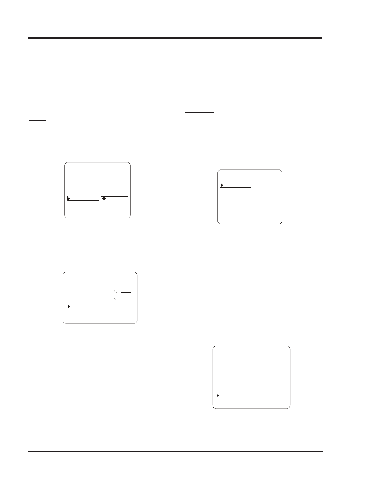
TIMER
On the optional installer’s remote, press MENU repeatedly until the Setup menu appears.
Press SELECT repeatedly to highlight the Timer option,
press the right arrow.
SETUP MENU
AUTO PROGRAM
ADD/DEL/BLNK
CH. LABELS
SOURCE NAME
CLOCK SET
TIMER
CAPTIONS
TILT
DEGAUSS
LANGUAGE
TO SET TIMER
Note: The clock must be set before for the Timers to
function.
The Off Timer can be used to turn the TV Off at the
present time.
No On Timer setting is required to use the Off Timer
feature.
CAPTIONS
Caption is a feature that allows the TV to receive closed
captions and/or text options when made available by
the broadcaster.
There are two operating modes for caption: quick/mute
or standard: If quick mute is selected, pressing the cc
keys switches the current cc selection On/Off.
CAPTIONS SETUP
OPER. MODE
SEL. CC TYPE
CAPTION LOCK
Use SELECT to choose an option. Use the number keypad and/or the Left/Right ADJ arrows to enter the times.
Use the timer key to set AM/PM.
Your options are:
TIMER
ON TIME 9:00 AM
OFF TIME 7:00 PM
ON/OFF TIMER ON
TIMER
TIMER
• On Time
Sets a time that the TV will turn itself On each day.
• Off Time
Sets a time that the TV will turn itself Off each day.
• On/Off Timer
Enables or disables the On/Off Timer functions. (The On/
Off Timer can be disabled but the setting will be retained)
Press ENTER to remove the menu and return to TV viewing
Use the Right/Left arrows to choose any of the following options: CAPTION 1, CAPTION 2, CAPTION 3, CAPTION 4, TEXT 1, TEXT 2, TEXT 3, TEXT 4 or OFF. Press
ENTER to close the menu.
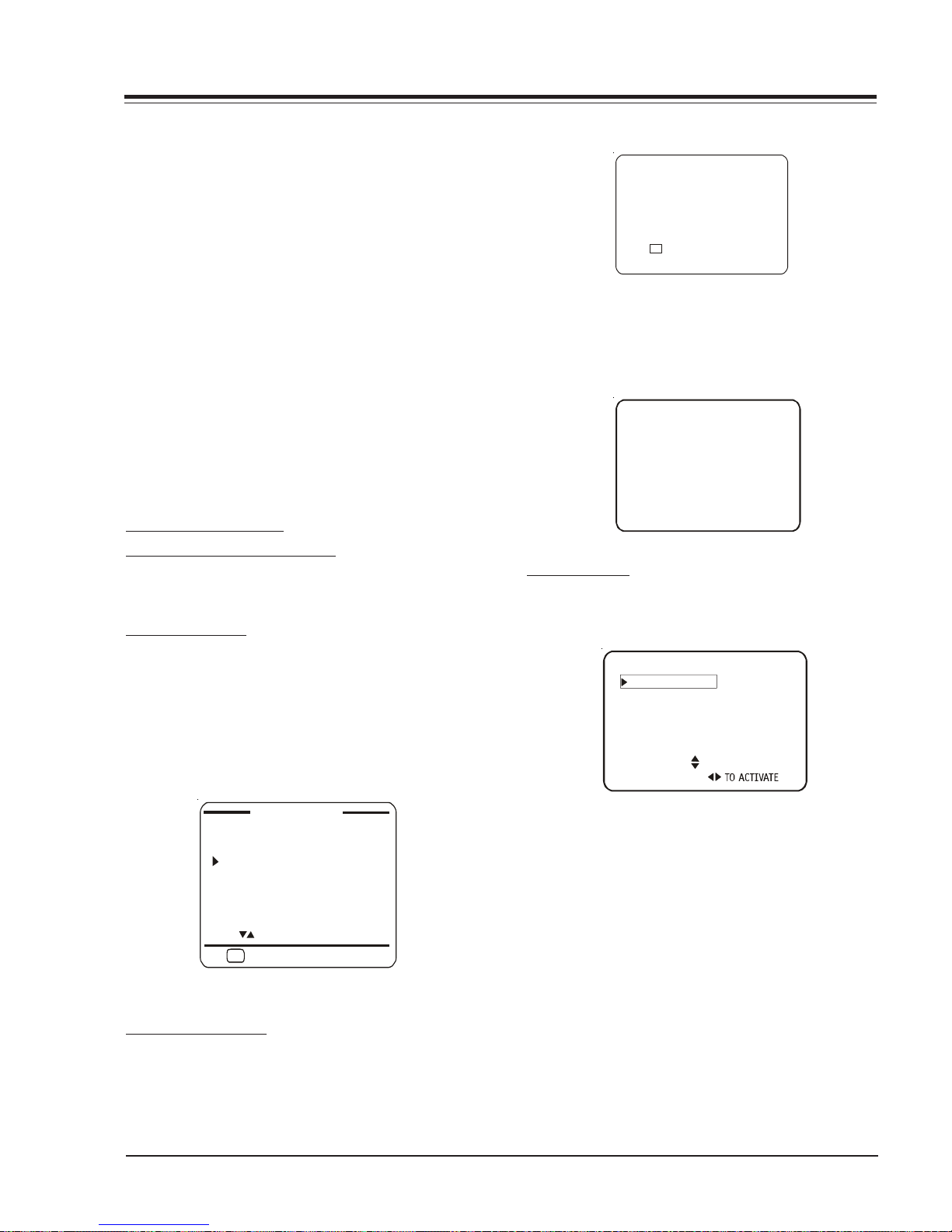
TILT
On the optional installer’s remote, press MENU repeatedly until the Setup Menu appears.
Press SELECT to highlight the Tilt Option on your screen.
Use the Left/Right ADJ arrows to adjust the tilt.
Press ENTER to return to TV viewing.
SETUP MENU
AUTO PROGRAM
ADD/DEL/BLNK
CH. LABELS
SOURCE NAME
CLOCK SET
TIMER
CAPTIONS
TILT
DEGAUSS
LANGUAGE
00
3828VD0210A 1-8 FCN - MENUS
USER MENUS
DEGAUSS
On the optional installer’s remote, press MENU repeatedly until the Setup Menu appears.
Press SELECT to highlight the Degauss Option on your
screen. Use the Left/Right ADJ arrows to select ON or
OFF. After the degaussing function works, ON mode
switches to OFF mode automatically.
Press ENTER to return to TV viewing.
SETUP MENU
AUTO PROGRAM
ADD/DEL/BLNK
CH. LABELS
SOURCE NAME
CLOCK SET
TIMER
CAPTIONS
TILT
DEGAUSS
LANGUAGE
ON
LANGUAGE
In the Language menu, use the Right/Left arrow to
choose one of the following options: English, Spanish,
or French. Press ENTER to return to TV viewing.
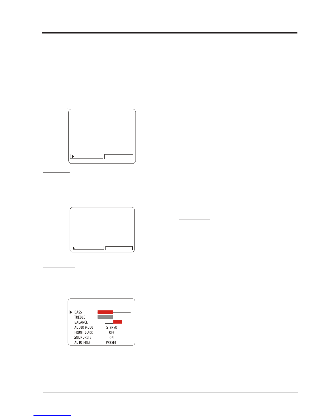
• BASS: Adjusts the amount of Bass (Low frequency level
in the sound. It has 15 steps (0 to 14).
• TREBLE: Adjusts the amount of Treble (High frequency
level) in the sound. It has 15 steps (0 to 14).
• BALANCE: Adjusts the balance of sound between the
left and right speakers. It has 29 steps (0 to 28).
• AUDIO MENU: Selects between Mono, Stereo and 2nd
Audio/SAP. If 2nd. AUdio/SAP is selected, but the
current channel does not support SAP either Stereo
or Mono will be heard.
• FRONT SURR: The Front Surround gives spatial effect
to the stereo material.
• SOUNDRITE: Used to obtain a uniform volume levelm,
particularly while changing channels.
• AUDIO PREF: This feature allows the customer to main
tain two separate audio settings by selecting “cus
tom” or “preset”. The factory gets the “Preset” set
ting and the customer sets “custom”.
Press a Right/Left ADJ arrow to adjust or change the
option you have selected. Press ENTER to return to TV
viewing, or press the Up Arrow to adjusts another option.
SETUP MENU
AUTO PROGRAM
ADD/DEL/BLNK
CH. LABELS
SOURCE NAME
CLOCK SE T
TIMER
CAPTIONS
TILT
DEGAUSS
LANGUAGE ENGLISH
AUDIO MENU
Press MENU repeatedly on the remote control until the
AUDIO MENU appears.
AUDIO MENU
Using the Up Arrow on the remote control, highlight
the setting you want to change. Choose from:
VIDEO MENU
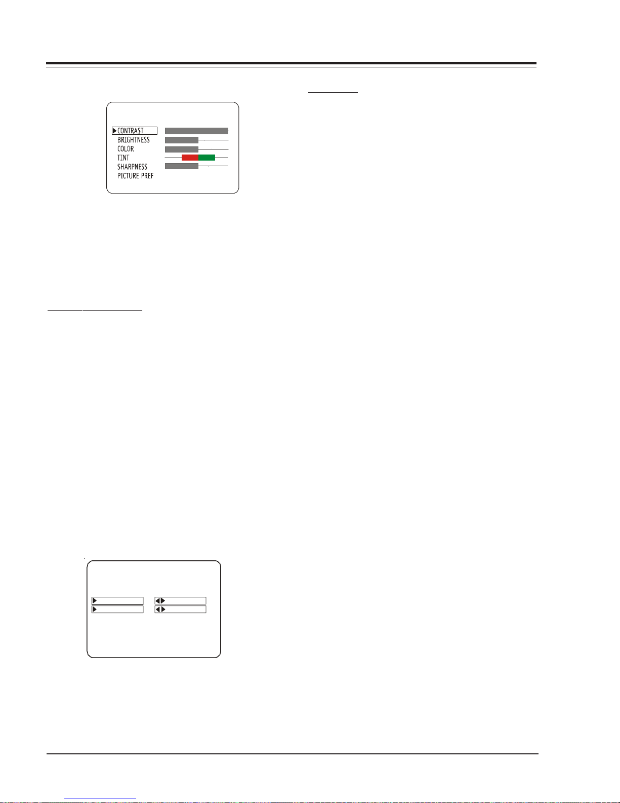
Press MENU repeatedly until the Video Menu appears.
Your options are:
• CONTRAST: Adjusts the contrast of the picture (differ-
ence between white and black). It has 64 steps (0 to
63).
• BRIGHTNESS: Adjusts the brightness of the picture
(amount of white). It has 64 steps (0 to 63).
• COLOR: Adjusts the intensity of the color. It has 64
steps (0 to 63).
• TINT: Adjusts the tint of the color picture (balances
between amounts of red and green in the TV pic
ture). It has 64 steps (0 to 63).
• SHARPNESS: Raises or lowers the definition of the TV
picture. The lower the level, the softer the images will
appear (adjusts the sharpness of the picture). It has
32 steps (0 to 31).
• PICTURE PREF: Has two settings: PRESET and CUSTOM.
In the Custom mode the brightness, contrast, color
and tint can be set to a users particular liking. The
preset settings brings up the factory setting for these
controls. Preset is selected automatically after an AC
power interruption.
3828VD0210A 1-9 FCN - MENUS
USER MENUS
VIDEO MENU
PRESET
Use the Up/Down arrows on the remote control to highlight the setting you want to change. Press Right/Left
Arrow to adjust or change the option you have selected.
Press ENTER to return to TV viewing, or press the Up/
Down Arrows to change other options in the video menu.
PARENTAL CONTROL
This optional feature can be used to prevent (block)
unwanted programming from appearing on your TV.
PARENTAL CONTROL offers the user a wid e vari ety of options and settings that restrict or block programming
that can appear on the TV. PARENTAL CONTROL allows
users the capability of defining which program ratings
they consider acceptable to younger or more sensitive
viewers.
PARENTAL CONTROL can be preset and turned on or off
by a user who specifies the 4 number password. The
number of hours blocked must also be specified.
General audience and children viewer blocks can both
be programmed in to th e TV’s memory. Viewer ratin gs are
specified for both the TV industry and the motion picture industry; both rating systems can be used. The
ratings are based mainly on children’s ages.
PARENTAL CONTROL
AU X BLO CK
MPAA RATING
AGE BL OC K
CONTE NT B LK
SET HOURS
SET PASSWORD
LOCK ON OFF
TO BLOCK
TO BLOCK
OVERVIEW
To en sure complete for all TV progr ams (movies an d regular TV shows), choose ratings from the Motion Picture
Associati on of Am eri ca (MPAA) Rating System chart and
the TV Parental Guidelines Rating System chart (both
shown in next page). Use the AGE BLOCK option for
General Audience and for Children. You can also add
additional restrictions from the CONTENT BLOCK menu.
Things to Consider before Setting Up Parental Control:
Determine which ratings you consider acceptable for
viewing. (For example, if you choose TV-PG, all of the
more restrictive ratings will be blocked automatically:
the viewer will not be able to see TV-PG, TV-14, or TVMA rated programming).
Select whether auxiliary video sources will be blocked
in the AUX SOURCES block option. (Blocks signals from
VCR’s, DVD players, etc. connected to the TV Audio/
Video input jacks). You could also leave AUX SOURCES
unblocked, and then choose allowable ratings.
In the CONTENT BLK option, you can block program Content based on individual parameters such as Strong Dialog, Bad Language, Sex Scenes, Violence Scenes, or Fantasy Violence Scenes.
You can set PARENTAL CONTROL to be active in the SET
HOURS option for up to 12 hours. Use the number keys
on the remote to select a secret password in the SET
PASSWORD option.
Don’t forget the password, as it is the only way you can
access the PARENTAL CONTROL menu and change rating
selections or turn PARENTAL CONTROL off.
If you do not want PARENTAL CONTROL to be active all
the time, you can turn it on or off with the LOCK ON/
OFF option.
Notes:
• You can set different PARENTAL CONTROL viewing
restrictions for general audiences and for
children - - both can be active at the same time.
• Simply specifying one content block such as Sex
Scenes, will not automatically block another
type of content in the programs from appearing.
• Even if you choose to leave the AUX INPUTS unblocked,
the ratings you specify will automatically restrict
the programming that appears from the video
sources.
3828VD0210A 1-10 FCN - MENUS
• You cannot disable PARENTAL CONTROL by
disconnecting the TV from power. Blocks hours
will automatically reset to the original block
time setting specified if power is disconnected.
USER MENUS
• To reset the password, use the installer’s remote
control to deactivate the V-Chip in the Installer’s
menu (#21). Exit out of the Installer’s Menu
after deactivating the Parental Control. Then
enter back in and reactive the V-Chip.
With the PARENTAL CONTROL menu on-screen, use the
Up Arrow to choose an option, such as CONTENT BLOCK.
Use the Left/Right arrow to show the CONTENT BLOCK
menu, to adjust or set the rating for an option.
To block sex scences, for example, use the “TV-PG and
above” setting. To block dialog, use LEFT/RIGHT ADJ
arrows to select among UNBLOCKED, TV-PG and above,
or TV-14. (See the Ratings Charts for rating meanings).
After you have selected and adjusted the P ARENT AL CONTROL menu options to your preferences:
- Set the number of hours Parental Control will be on.
- Set a 4 number password.
- Set the Lock On/Off option to either on or off.
ON-SCREEN DISPLAYS
CHANNEL/TIME/AUDIO DISPLA Y
Press ENTER. Shows currently selected channel or source,
current time if the clock has been set, and incoming
audio signal.
CH PREVIEW MENU
Press SURF. Displays list of the available TV Channels,
Guest Parental Control menu (if active) and Video Channel access.
Press CHANNEL UP/DOWN to select a channel, and then
ENTER to go to that channel. Pressing CC will activate
the Parental Control menu.
CC
CAPTIO N 1 IS ON
In the Standard Mode, it displays all the Captions and
Text mode selections as below:
CAPTION 1
CAPTION 2
CAPTION 3
CAPTION 4
TEXT 1
TEXT 2
TEXT 3
TEXT 4
OFF
SOURCE MENU
Scrolling the menus using the Menu key can access the
Source Menu.
SOURCE MENU
ANTENNA/CABLE
CAMPORT
F S-VIDEO
R S-VIDEO
COMP (YPrPb)
REAR AUX.
PRESS TO CHANGE
PRESS ENTER OR
CHANNEL PREVIEW
5 - - - 9 - - - 20 - - - 32 - - - -
AUX - - - -
2 - - - -
CH TO SELECT , ENTER TO QUIT
CC FOR PARENTAL CONTROL
CAPTIONS DISPLAY
Pressing CC in Quick Mode shows the current Caption
selection, or Caption Off:
3828VD0210A 1-11 FCN - MENUS
Use the Up/Down Arrows to navigate among Source
options and use Select, Enter or Right/Left Arrows to
enter a desired source.

USER MENUS
MOTION PICTURE ASSOCIATION OF AMERICA (MPAA) RATING SYSTEM
G General Audiences Content not offensive to most viewers.
PG Parental Guidance Content is such that parents may not want their children to view the program.
Suggested
PG-13 Parental Guidance Program is inappropriate for preteens, with a greater degree of offensive
Suggested material than a PG-rated program.
R Restricted Viewing Not for children under age 17. Strong elements of sex and/or violence.
NC-17 Restricted Viewing Not for children under age 17 under any circumstances. Strong sexual content .
X Hard Core Films Same as NC-17 rating.
Note: LG Electronics Corporation is not liable for any program content that appears when using this rating system;
as always, user discretion is advised.
TV PARENTAL GUIDELINE RATING SYSTEM
G General Audienc es Content not offensive to most viewers.
TV-G General Audience Considered suitable for all audiences: children may wat ch unattended.
TV-PG Parental Guidance Unsuitable for younger children, may contain: Suggestive Dialog, Bad Language,
Suggested Sex, and Violence Scenes.
TV-14 Parents Strongly Unsuitable for children under 14, may contain: Strong Dialog, Bad Lang uage,
Cautioned Sex, and Violence Scenes.
TV-MA Mature Audience Only Adults only, may contain: Stron g Dialog, Bad Language, Sex, and Violence Scenes.
CHILDREN'S CLASSIFICATIONS
TV-Y Children Considered suitable for all children under 7 years old.
TV-Y7 Children 7 and over Considered suitable for children over 7, may contain Fant asy Violence Scenes.
3828VD0210A 1-12 FCN - MENUS

INSTALLERS MENU
INSTALLER’S MENU ADJUSTMENTS
Installer’s menu items can be accessed by using the
optional LP702 installer’s remote control. Just press and
hold MENU (about 8 seconds) until the display changes,
then press 9, 8, 7, 6, then ENTER. To exit the Installer’s
Menu, press ENTER again. Any changes you make will be
stored in nonvolatile memory.
The Installer’s men u opens with item 0-I, INST . SEQ. Use
the SELECT key to sequence through the available menu
items. T o chang e a setting use th e Left/Righ t ADJ keys .
Using the Installer’s Menu
Items 0-I - 95-I are accessible only in the Installer’s
Menu. Their numbers, descriptions, ranges, factory default settings, and a place for listing any changes made
onsite are given below and on the following pages. The
Factory Menu that is intended for qualified service technicians only, is not shown (XX-F items). Normally Factory menu items do not require adjustment.
INSTALLERS
INSTALLER 1
INSTALLER 2
INSTALLER 3
INSTALLER 4
INSTALLER 5
INSTALLER 6
INSTALLER 7
V 1.17
Typical Installer Menu
NOTE: When set to 1 (ON), the TV does not respond to
ON/OFF commands from either the remote or the control
panel, and the SLEEP TIMER is also nonfunctional.
3-I. BAND/AFC (Band/Automatic Frequency Control)
There are 8 possible settings for this option:
0 = Broadcast Fixed 4 = Broadcast AFC
5 = CATV Fixed 1 = CATV AFC
6 = HRC Fixed 2 = HRC AFC
7 = ICC Fixed 3 = ICC AFC
Channels are accessed faster when fixed modes are used.
The AFC (search modes) should only be used when some
channels are not on nominal frequencies.
NOTE: BAND is automatically set by AUTO PROGRAM.
If some channels were not found by AUTO PROGRAM,
select the appropriate AFC setting here and add the
channels using the ADD/DEL option in the Setup Menu.
4-I. STRT CHANNEL (Start Channel)
When active, this function allows you to determine the
initial channel number when the TV is turned ON. This
feature is useful for an in-house information channel,
since the TV would always select that channel when it is
turned on. Setting this to 255 causes the last channel
viewed when TV was turned off to be the tuned to
channel when the TV is turned on again.
The range of values is 0 - 255. Use ADJ (adjust) keys to
choose numbers that determine the start channel.
0-I. INSTALLER SEQUENCE
Gives access to Installer Menu depending on the code
selected.
0 = 9876 1 = 4321
2 = 1478 3 = 3698
1-I. POWER MANAGE (Power Management)
Determines hours of no activity before automatic shutoff.
The POWER MANAGE functi on is f or saving en ergy. When
set to 0, Power Manage is OFF. Settings range from 0 7, with 1 - 7 representing the hours that the TV will
remain on, unless there has been activity from either
the control panel or remote control.
2-I. AC ON (AC Power Switchable)
Allows the TV to turn ON just by applying AC power.
Pressing the ON button is n ot necessary . This is desir able
when the TV is plugged into a cable box or a power
outlet controlled by a wall switch. Use ADJ to select 0
or 1, where 0 is the default is OFF, and 1 is ON.
5-I. CHAN LOCK (Channel Lock)
CHAN LOCK is ideal if a cable box (or similar) is the sole
source for programming—and the TV must always be on
the same channel.
Changing channels with Channel Up/Down or keypad
numbers is impossible. Channel Lock is inactive when
set to 0 (default).
Generally , this feature is used in conjun ction with ST ART
CHANNEL (item 4-I.) where the start channel may, for
example, be set to 3 or 4. If the start channel is 3, then
the TV will remain on channel 3. NOTE: When CHANNEL
LOCK is active and CHANNEL OVERIDE is disabled, AUTO
PROGRAM is not functional.
6-I. GHOST CH (Ghost Channel)
When set to 1, the current channel number is displayed
in the upper right corner of the picture. The number
moves slightly to prevent damage to the screen. The
default is “0” or OFF . NO TE: When captions ar e on, “Ghost
Channel” is not displayed.
3828VD0210A 2-1 FCN - INSTALLERS MENU
 Loading...