

LG RU-20LA61 Service Manual

LCD TV
SERVICE MANUAL
CAUTION
BEFORE SERVICING THE CHASSIS,
READ THE SAFETY PRECAUTIONS IN THIS MANUAL.
CHASSIS : ML-012B
MODEL : RU-20LA61
website:http://biz.LGservice.com
e-mail:http://www.LGEservice.com/techsup.html
MONO DPM
STEREO
ST
SAP
- 2 -
SAFETY PRECAUTIONS
Many electrical and mechanical parts in this chassis have special safety-related characteristics. These parts are identified by in
the Schematic Diagram and Replacement Parts List.
It is essential that these special safety parts should be replaced with the same components as recommended in this manual to
prevent X-RADIATION, Shock, Fire, or other Hazards.
Do not modify the original design without permission of manufacturer.
General Guidance
An lsolation Transformer should always be used during
the servicing of a receiver whose chassis is not isolated from
the AC power line. Use a transformer of adequate power rating
as this protects the technician from accidents resulting in
personal injury from electrical shocks.
It will also protect the receiver and it's components from being
damaged by accidental shorts of the circuitary that may be
inadvertently introduced during the service operation.
If any fuse (or Fusible Resistor) in this TV receiver is blown,
replace it with the specified.
When replacing a high wattage resistor (Oxide Metal Film
Resistor, over 1W), keep the resistor 10mm away from PCB.
Keep wires away from high voltage or high temperature parts.
Due to high vacuum and large surface area of picture tube,
extreme care should be used in handling the Picture Tube.
Do not lift the Picture tube by it's Neck.
Before returning the receiver to the customer,
always perform an AC leakage current check on the exposed
metallic parts of the cabinet, such as antennas, terminals, etc.,
to be sure the set is safe to operate without damage of
electrical shock.
Leakage Current Cold Check(Antenna Cold Check)
With the instrument AC plug removed from AC source,
connect an electrical jumper across the two AC plug prongs.
Place the AC switch in the on positioin, connect one lead of
ohm-meter to the AC plug prongs tied together and touch other
ohm-meter lead in turn to each exposed metallic parts such as
antenna terminals, phone jacks, etc.
If the exposed metallic part has a return path to the chassis, the
measured resistance should be between 1MΩ and 5.2MΩ.
When the exposed metal has no return path to the chassis the
reading must be infinite.
An other abnormality exists that must be corrected before the
receiver is returned to the customer.
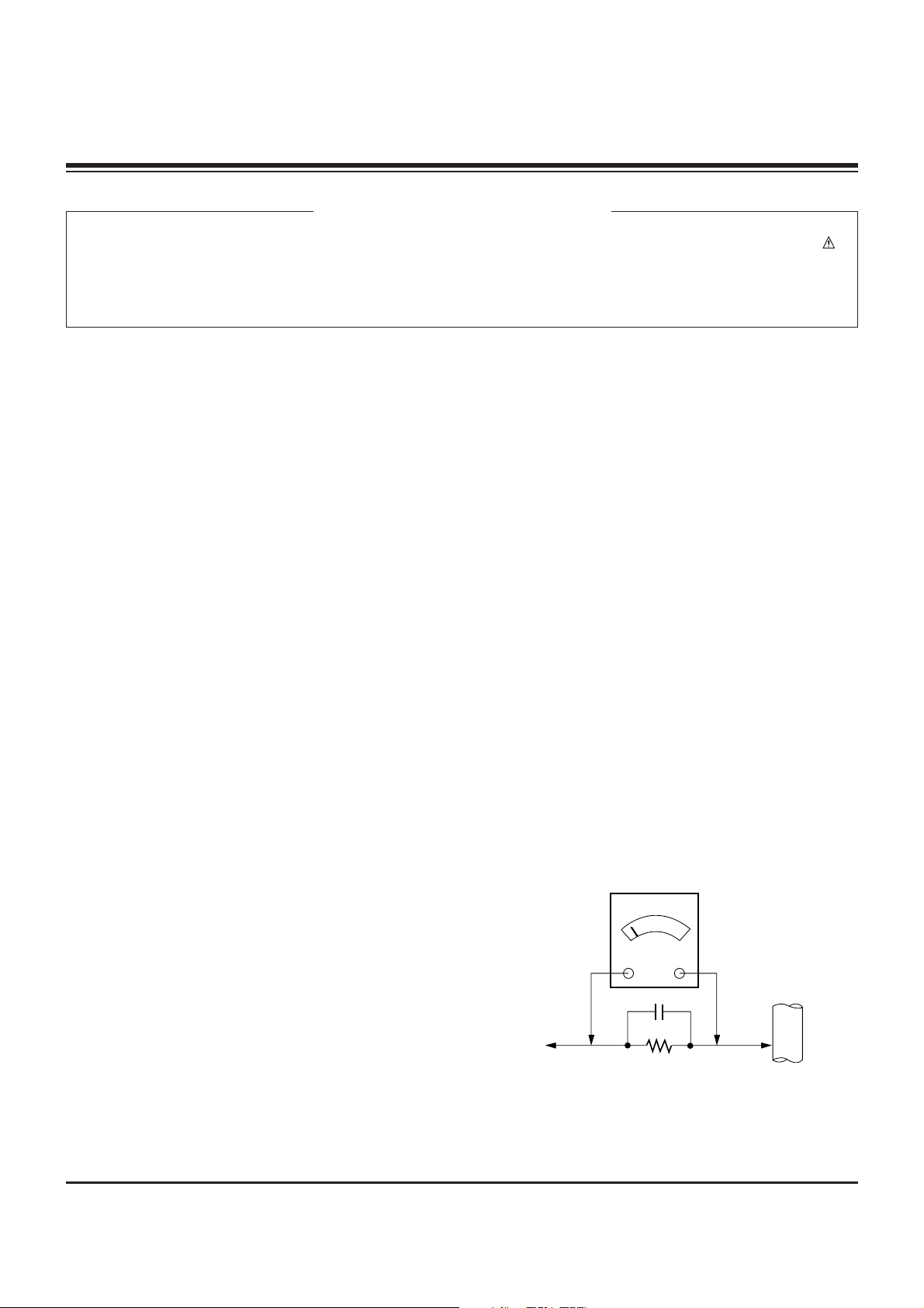
Leakage Current Hot Check (See below Figure)
Plug the AC cord directly into the AC outlet.
Do not use a line Isolation Transformer during this check.
Connect 1.5K/10watt resistor in parallel with a 0.15uF capacitor
between a known good earth ground (Water Pipe, Conduit, etc.)
and the exposed metallic parts.
Measure the AC voltage across the resistor using AC
voltmeter with 1000 ohms/volt or more sensitivity.
Reverse plug the AC cord into the AC outlet and repeat AC
voltage measurements for each esposed metallic part. Any
voltage measured must not exceed 0.75 volt RMS which is
corresponds to 0.5mA.
In case any measurement is out of the limits sepcified, there is
possibility of shock hazard and the set must be checked and
repaired before it is returned to the customer.
Leakage Current Hot Check circuit
1.5 Kohm/10W
To Instrument's
exposed
METALLIC PARTS
Good Earth Ground
such as WATER PIPE,
CONDUIT etc.
AC Volt-meter
IMPORTANT SAFETY NOTICE
0.15uF

- 3 -
SPECIFICATIONS.................................................................4
DESCRIPTION OF CONTROLS...........................................5
ADJUSTMENT INSTRUCTIONS ..........................................9
PRINTED CIRCUIT BOARD ...............................................10
BLOCK DIAGRAM...............................................................13
EXPLODED VIEW...............................................................14
EXPLODED VIEW PARTS LIST.........................................15
REPLACEMENT PARTS LIST............................................16
SCHEMATIC DIAGRAM..........................................................
TABLE OF CONTENTS
- 4 -
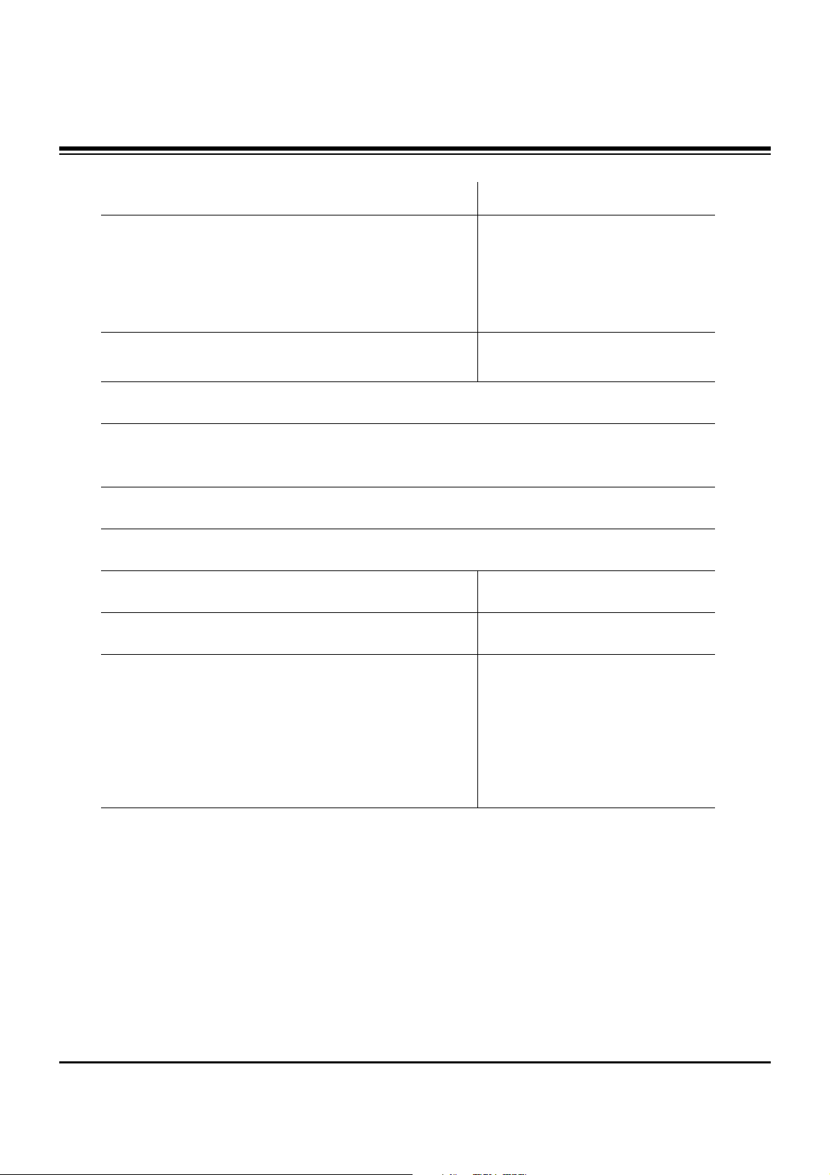
SPECIFICATIONS
Model RU-15LA61 RU-20LA61
Horizontal size (Inches) 18.3 22.8
Height (Inches) 14.8 18.3
Thickness (Inches) 6.7 8
Weight (pounds) 13.9 21.6
Power requirements DC 12V/4.5A DC 15V/4.5A
Television system NTSC
Television channels VHF : 2 ~ 13, UHF : 14 ~ 69
Cable : 01 ~ 125
Television Screen LCD Panel
External antenna impedance 75 Ω
Power consumption 50 W 70 W
Audio output 3 W + 3 W 5 W + 5 W
Adapter (DC power) In : AC 100-240V ~ 1.5A-0.6A
50/60Hz, 115~180VA
Out : DC 12V, 5A
* CAUTION : For use only with Model No. SAD6012SE AC Adapter, manufactured by H &
E co., Ltd.
Power supply cordset : Standard North America three wire earth-grounding with
flexible cord SJT type or higher type.
* CAUTION : If replacement becomes necessary, replace with an exact duplicate.
Contact any LG authorized service center.
In: AC 100-240V ~ 1.6A-0.7A
50/60Hz
Out: DC 15V, 4.5A
For use only with Model No.
SAD7015SE AC Adapter,
manufactured by H & E co., Ltd.
In: AC 100-240V ~ 1.5A-0.6A
50/60Hz
Out: DC 12V, 5A
For use only with Model No.
SAD6012SE AC Adapter, manufactured by H & E co., Ltd.
- 5 -
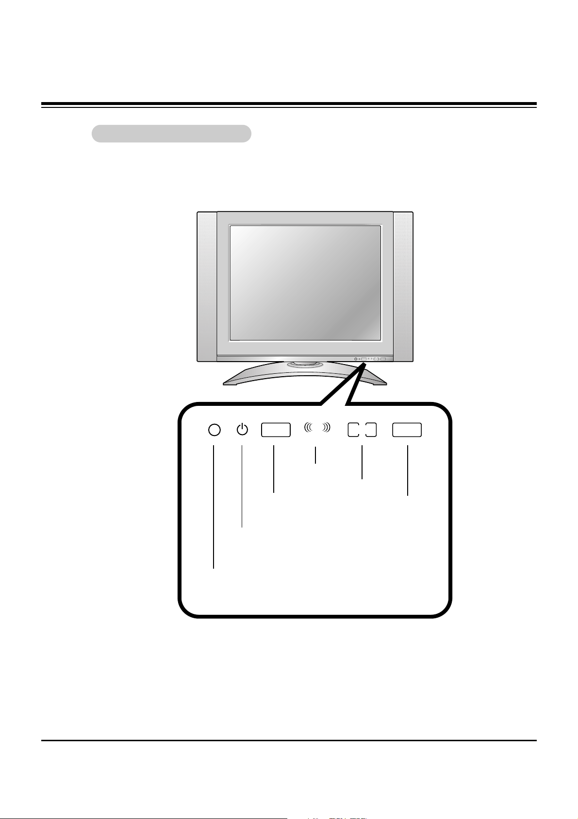
DESCRIPTION OF CONTROLS
Front of the
Front of the TVTV
MONO DPM
STEREO
ST
SAP
MONO DPM
SAP
STEREO
ST
Remote Control Sensor
DPM Indicator
(RU-15LA61 Only)
SAP Indicator
Mono Indicator
Stereo Indicator
Power/Standby indicator
Illuminates red in standby mode, Illuminates
green when the TV is turned on.
- 6 -
DC IN (15V)
ANT IN
+75 Ω
COMPONENT(480i/480p/720p/1080i)
VIDEO IN
DVD/DTV IN
AUDIO
RLVIDEO
P
R
P
B
Y L R
AUDIO(MONO)
DC 12V
ANT IN
+75 Ω
PC INPUT
COMPONENT(480i/480p/720p/1080i)
PC
SOUND
VIDEO IN
DVD/DTV IN
AUDIO
RLVIDEO
P
R
P
B
Y L R
AUDIO(MONO)
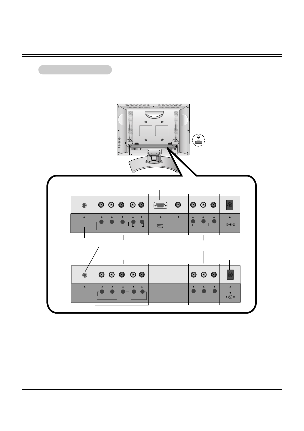
Back of the
Back of the TVTV
Audio/Video Input
- This manual mainly explains the features for the RU-15LA61
PC Input
PC sound Input
Antenna Input
DC 12V Input
DVD/DTV IN
(Component (480i/480p/720p/1080i),
AUDIO) Input
RU-15LA61
RU-15LA61
RU-20LA61
RU-20LA61
* Kensington
Security System
Connector
DC 15V Input
DESCRIPTION OF CONTROLS
- 7 -
MONO DPM
STEREO
ST
SAP
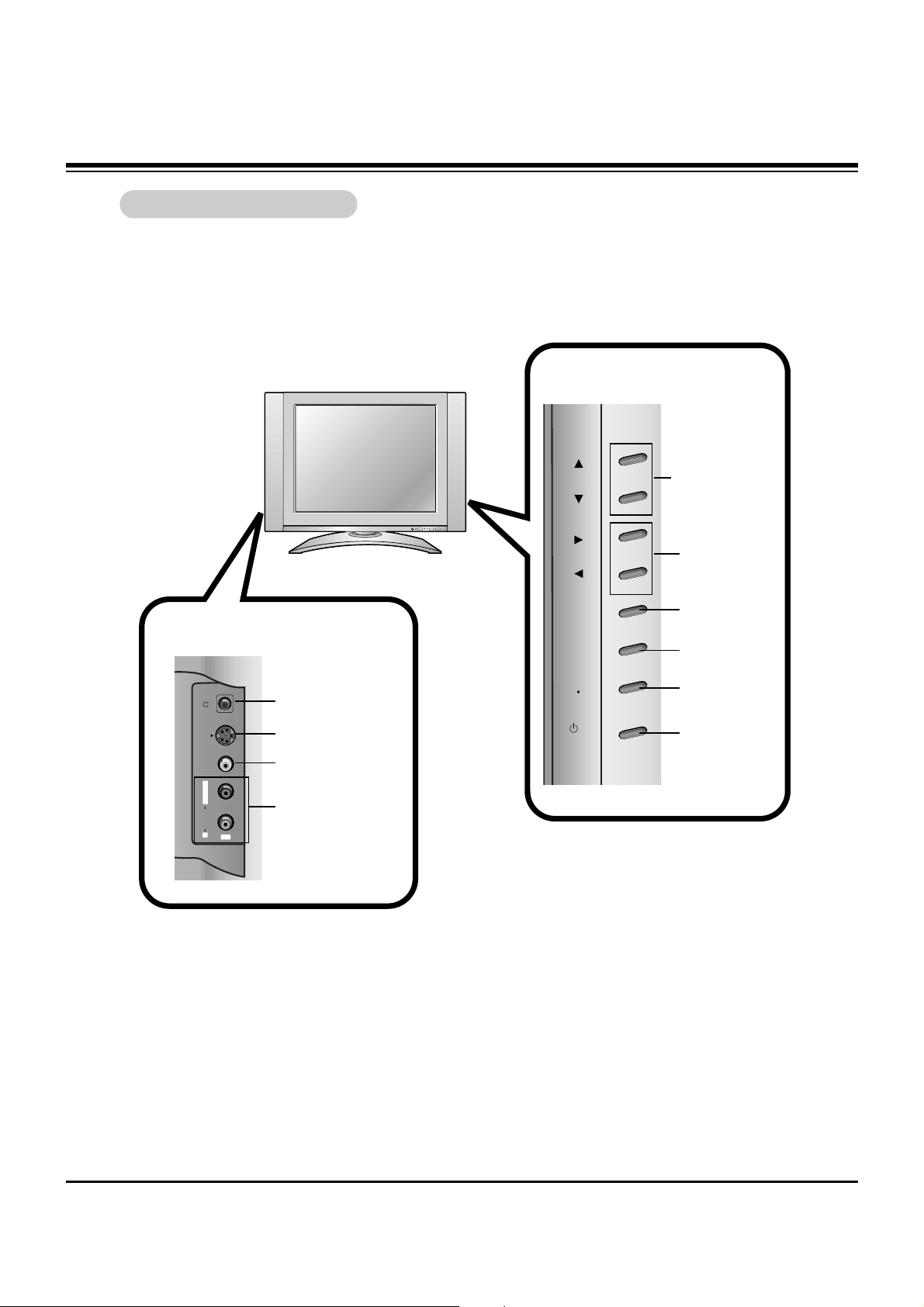
Side of the
Side of the TVTV
S-VIDEO VIDEO
AUDIO
R
IN2
L / MONO
Side Control Panel
Side Control Panel
Side Connection Panel
Side Connection Panel
Channel Buttons
Volume Buttons
ch
vol
menu
enter
on/off
tv
video
/ I
Enter Button
Menu Button
TV·Video Button
On/Off Button
Headphone Jack
S-Video Input
Video Input
Audio Input
DESCRIPTION OF CONTROLS
 Loading...