

LG RT-32FZ32RP Service Manual
COLOR TV
SERVICE MANUAL
CAUTION
BEFORE SERVICING THE CHASSIS,
READ THE SAFETY PRECAUTIONS IN THIS MANUAL.
CHASSIS : MC-021A
MODEL:RT-32FZ32RP
website:http://biz.LGservice.com
e-mail:http://www.LGEservice.com/techsup.html
May.,2003
Printed in KoreaP/NO : 3828VD0130G
ON/OFF
MENUOK VOL PR

- 2 -
CONTENTS
CONTENTS ............................................................................................................ 2
SAFETY PRECAUTIONS....................................................................................3
SPECIFICATIONS................................................................................................. 4
CONTROL DESCRIPTIONS ............................................................................ 5
DISASSEMBLY INSTRUCTIONS .................................................................. 8
ADJUSTMENT INSTRUCTIONS ................................................................. 9
TROUBLE SHOOTING...................................................................................... 14
BLOCK DIAGRAM ............................................................................................. 19
EXPLODED VIEW .............................................................................................. 20
EXPLODED VIEW PARTS LIST .....................................................................21
REPLACEMENT PARTS LIST ...................................................................... 22
SVC. Sheet ................................................................................................................
- 3 -
SAFETY PRECAUTIONS
Many electrical and mechanical parts in this chassis have special safety-related characteristics. These parts are identified by in
the Schematic Diagram and Replacement Parts List.
It is essential that these special safety parts should be replaced with the same components as recommended in this manual to
prevent X-RADIATION, Shock, Fire, or other Hazards.
Do not modify the original design without permission of manufacturer.
General Guidance
An isolation Transformer should always be used during
the servicing of a receiver whose chassis is not isolated from
the AC power line. Use a transformer of adequate power rating
as this protects the technician from accidents resulting in
personal injury from electrical shocks.
It will also protect the receiver and it's components from being
damaged by accidental shorts of the circuitary that may be
inadvertently introduced during the service operation.
If any fuse (or Fusible Resistor) in this TV receiver is blown,
replace it with the specified.
When replacing a high wattage resistor (Oxide Metal Film
Resistor, over 1W), keep the resistor 10mm away from PCB.
Keep wires away from high voltage or high temperature parts.
Due to high vacuum and large surface area of picture tube,
extreme care should be used in handling the Picture Tube.
Do not lift the Picture tube by it's Neck.
X-RAY Radiation
Warning:
To determine the presence of high voltage, use an accurate
high impedance HV meter.
Adjust brightness, color, contrast controls to minimum.
Measure the high voltage.
The meter reading should indicate
23.5
¡ 1.5KV: 14-19 inch, 26 ¡ 1.5KV: 19-21 inch,
29.0 ¡ 1.5KV: 25-29 inch, 30.0 ¡ 1.5KV: 32 inch
If the meter indication is out of tolerance, immediate service
and correction is required to prevent the possibility of
premature component failure.
Before returning the receiver to the customer,
always perform an AC leakage current check on the exposed
metallic parts of the cabinet, such as antennas, terminals, etc.,
to be sure the set is safe to operate without damage of
electrical shock.
Leakage Current Cold Check(Antenna Cold Check)
With the instrument AC plug removed from AC source,
connect an electrical jumper across the two AC plug prongs.
Place the AC switch in the on positioin, connect one lead of
ohm-meter to the AC plug prongs tied together and touch other
ohm-meter lead in turn to each exposed metallic parts such as
antenna terminals, phone jacks, etc.
If the exposed metallic part has a return path to the chassis, the
measured resistance should be between 1MΩ and 5.2MΩ.
When the exposed metal has no return path to the chassis the
reading must be infinite.
An other abnormality exists that must be corrected before the
receiver is returned to the customer.
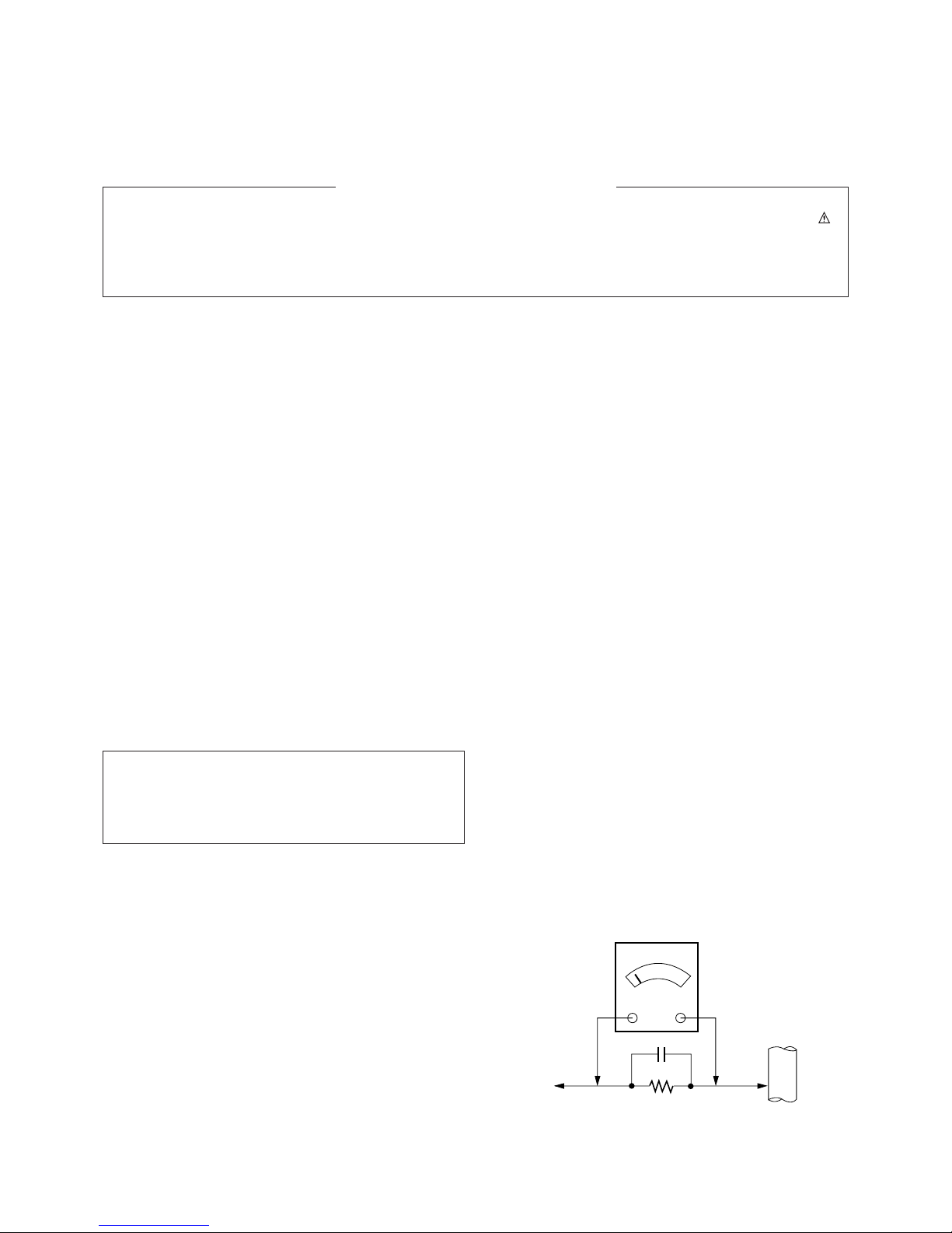
Leakage Current Hot Check (See below Figure)
Plug the AC cord directly into the AC outlet.
Do not use a line Isolation Transformer during this check.
Connect 1.5K/10watt resistor in parallel with a 0.15uF capacitor
between a known good earth ground (Water Pipe, Conduit, etc.)
and the exposed metallic parts.
Measure the AC voltage across the resistor using AC
voltmeter with 1000 ohms/volt or more sensitivity.
Reverse plug the AC cord into the AC outlet and repeat AC
voltage measurements for each esposed metallic part. Any
voltage measured must not exceed 0.75 volt RMS which is
corresponds to 0.5mA.
In case any measurement is out of the limits specified, there is
possibility of shock hazard and the set must be checked and
repaired before it is returned to the customer.
Leakage Current Hot Check circuit
The source of X-RAY RADIATION in this TV receiver is the
High Voltage Section and the Picture Tube.
For continued X-RAY RADIATION protection, the
replacement tube must be the same type tube as specified in
the Replacement Parts List.
1.5 Kohm/10W
To Instrument's
exposed
METALLIC PARTS
Good Earth Ground
such as WATER PIPE,
CONDUIT etc.
AC Volt-meter
IMPORTANT SAFETY NOTICE
0.15uF

- 4 -
SPECIFICATIONS
Note : Specification and others are subject to change without notice for improvement.
O Video input system:
PAL-B/G, D/K, I/I
SECAM-B/G, D/K/L/L’
NTSC M
O Intermediate Frequency (Unit : MHz)
VISION IF. : 38.9MHz,33.9MHz(SECAM-L’)
COLOR IF. : 34.47MHz(4.43)
35.32MHz(3.58) : NTSC-M
VIF-4.25000MHz
VIF-4.40625MHz
SOUND IF : 33.4MHz (B/G)
32.9MHz (I/I)
32.4MHz (D/K,L)
34.4MHz (M)
40.4MHz (L’)
O Power requirement : AC 110-240V, 50/60Hz
O Power consumption : Max. 160W
O CPT : Flat CPT
O Tuning system :
FVS
100 Programme memory
200 Programme memory (W/O TXT)
O
Antenna input impedance : VHF/UHF 75 ohm, unbalanced
O Voice coil impedance : 8 ohm
O External connection :
AV Input: 4 (side or front:1,rear:2)
Component Input: 2 (rear)
PERI TV Connector: Full Scart:1(AV Input or Scart option)
R,G,B Input: 1(option)
O External In/Output
Audio-In:0.5Vrms
!3db,over 10Kohm
Audio-Out:0.5Vrms!3db,below 1Kohm
Video-In/Out:1Vp-p!3db,75ohm
R,G,B In:0.7Vp-p!3db
O Feature : NICAM Stereo/Dual
2 Carrier Stereo/Dual
SSC mode(Split Screen)
Multi Picture Display mode(1:4:9 PIP)
Film mode
DBS(option)
Teletext (TOP/FLOF 128 page)
Noise Reduction
Progressive Scan
Motion Detection
Digital EYE
O Tuning range
Band
VHF-Low
VHF-High
Hyper
UHF
S1'-S3', S1
S2-S10,
S11-S20
S21-S41
For TV
For CATV
B/G
Ch2-4
Ch5-12
D/K
Ch1-5
Ch6-12
I/I
Ch4-13
NTSC
Ch2-13
Ch21-69 Ch14-69
(
): SECAM
- 5 -
CONTROL DESCRIPTIONS
PSM
I / II DRP PICTURE
MENU
PIP MUTE
PIP PR
PIP INPUT
POSITION
SCAN
MIX
LIST
P/STILL
STOP REC
REW PLAY FF
TIME
REVEAL SLEEP
STILL SIZE
PIP SWAP TEXT
PR
OK
PR
VOL
SOUND
TV/AV
POWER
123
456
78
0
9
SSM
i
M
?
T
U
R
B
O
VOL
PIP PR ARC
EYE/
1
2
3
4
5
6
7
8
9
10
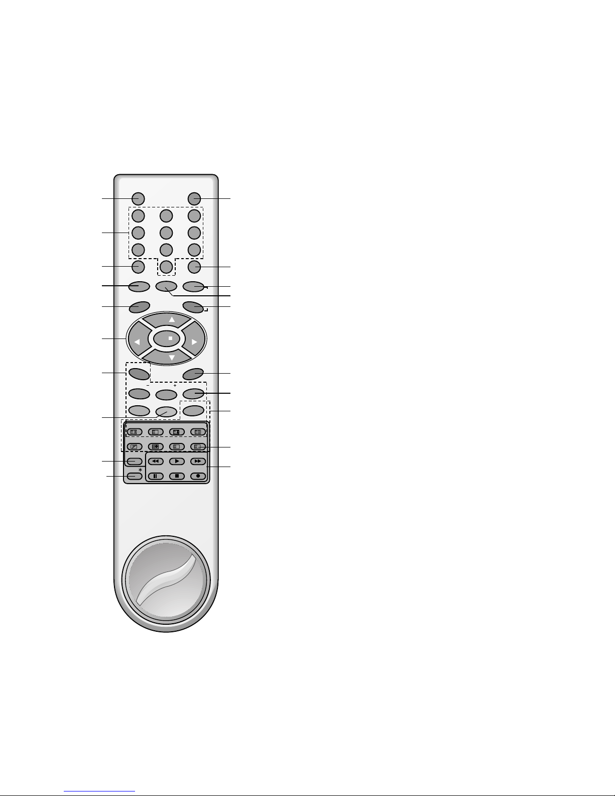
All the functions can be controlled with the remote control handset.
Some functions can also be adjusted with the buttons on the front
panel of the set.
Remote control handset
Before you use the remote control handset, please install the batteries. See the next page.
1. TV/AV
selects TV or AV mode.
switches the set on from standby.
2. NUMBER BUTTONS
switches the set on from standby or directly select a number.
3. PSM (Picture Status Memory)
recalls your preferred picture setting.
4. I/II
selects the language during dual language broadcast.
selects the sound output (option).
5. MENU
selects a menu.
6.
DD / EE
(Programme Up/Down)
selects a programme or a menu item.
switches the set on from standby.
FF / GG
(Volume Down/Up)
adjusts the volume.
adjusts menu settings.
OK
accepts your selection or displays the current mode.
7. PIP BUTTONS
PIP
switches the sub picture on or off.
PIP PR +/
-
selects a programme for the sub picture.
PIP SWAP
alternates between main and sub picture.
PIP INPUT
selects the input mode for the sub picture.
SIZE
adjusts the sub picture size.
STILL
freezes motion of the sub picture.
POSITION
relocates the sub picture in clockwise direction.
SCAN
switches on or off the programme scan mode through 12 sub
pictures.
8. PIP SWAP
returns to the previously viewed programme.
selects a favourite programme.
9. LIST
displays the programme table.
10. EYE/*(option)
switches the eye function on or off.
11
13
12
15
16
17
19
20
18
14

- 6 -
11. POWER
switches the set on from standby or off to standby.
12. SSM (Sound Status Memory)
recalls your preferred sound setting.
13. TURBO PICTURE BUTTON
selects Turbo picture.
14. DRP (Digital Reality Picture)
switches DRP Pro or 100.
15. TURBO SOUND BUTTON
selects Turbo sound.
16. MUTE
switches the sound on or off.
17. ARC (Aspect Ratio Control)
changes the picture format.
18. TELETEXT BUTTONS (option)
These buttons are used for teletext.
For further details, see the ‘Teletext’ section.
19. SLEEP
sets the sleep timer.
20. VCR BUTTONS
control a LG video cassette recorder.
Note : In teletext mode, the PIP PR +/-, PIP SWAP and PIP INPUT
buttons are used for teletext function.
Internal generator charge
The remote control handset can be charged with the internal electric
generator. To charge the remote control handset do the followings;
1. In first use,
20 rotation of the handle in the arrow direction as picture below
-> waiting for one minute -> 20 rotation again -> waiting for one
minute again -> 20 rotation again -> beginning to use
2. In usual use
5 or 6 rotation -> resuming to use
Note : Do not rotate the handle too rapidly for the protection of the
remote control handset.
PSM
I / II DRP PICTURE
MENU
PIP MUTE
PIP PR
PIP INPUT
POSITION
SCAN
LIST
P/STILL
STOP REC
REW PLAY FF
SLEEP
STILL SIZE
PIP SWAP
PR
OK
PR
VOL
SOUND
TV/AV
POWER
1 2 3
4 5 6
7 8
0
9
SSM
T
U
R
B
O
VOL
PIP PR ARC
EYE/
1
2
3
4
5
6
7
8
9
10
11
13
12
15
16
17
19
20
14
- 7 -
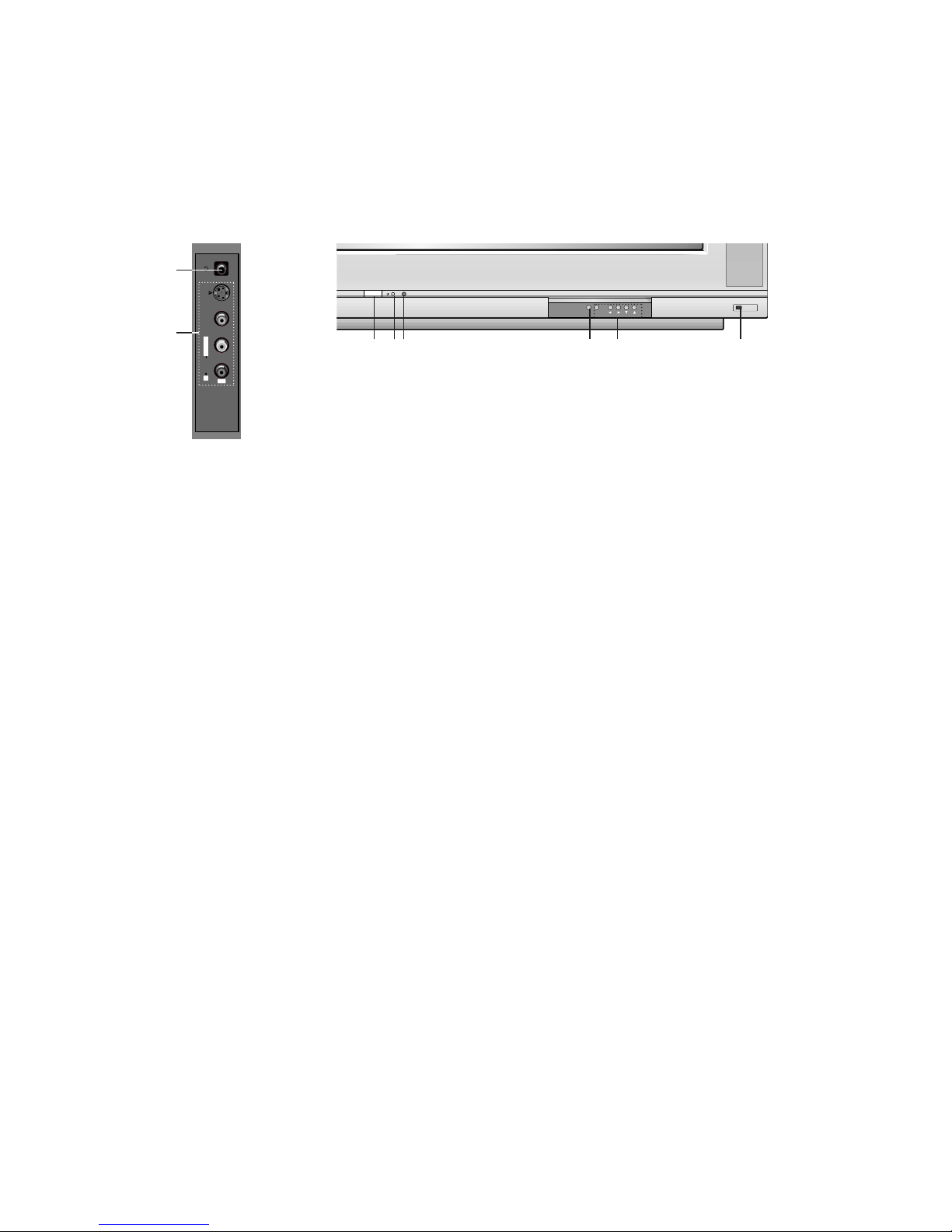
1. MAIN POWER (ON/OFF)
switches the set on or off.
2. POWER/STANDBY INDICATOR
illuminates brightly when the set is in standby mode.
dims when the set is switched on.
3. REMOTE CONTROL SENSOR
4. MENU
selects a menu.
5. OK
accepts your selection or displays the current mode.
FF / GG
(Volume Down/Up)
adjusts the volume.
adjusts menu settings.
DD / EE
(Programme Up/Down)
selects a programme or a menu item.
switches the set on from standby.
6. EYE (option)
adjusts picture according to the surrounding conditions.
7. HEADPHONE SOCKET
Connect the headphone plug to this socket.
8. AUDIO/VIDEO IN SOCKETS (AV4)
Connect the audio/video out sockets of external equipment to
these sockets.
S-VIDEO/AUDIO IN SOCKETS (S-AV)
Connect the video out socket of an S-VIDEO VCR to the SVIDEO socket.
Connect the audio out sockets of the S-VIDEO VCR to the
audio sockets as in AV4.
Front panel
S-VIDEO
VIDEO
L/MONO RAUDIO
AV4
7
8
Side panel
ON/OFF
MENU OK VOL PR
1 23 4 65
RF/RT-32FZ32 series
- 8 -
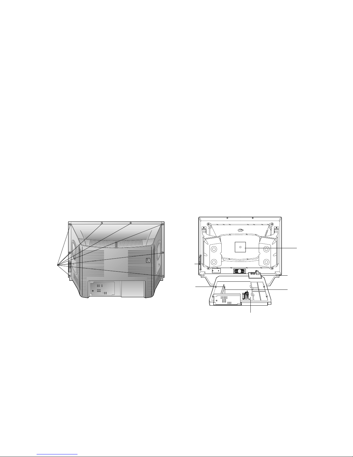
4
Fig. 2-1 Fig. 2-2
CPT
PCB
Remove
Screws
Main PCB
A/V PCB
Control
PCB
MICOM
PCB
VCD
PCB
DISASSEMBLY INSTRUCTIONS
Important note
This set is disconnected from the power supply through the
converter transformer. An isolating transformer is necessary
for service operations on the primary side of the converter
transformer.
Back Cabinet Removal
Remove the screws residing on the back cabinet and carefully
separate the back cabinet from the front cabinet. (Fig. 2-1).
Chassis Assy Removal
Grasp both side of Frame and pull it backward smoothly.
CPT Removal
1. Pull out the CPT board from the CPT neck.
2. Place the front cabinet on soft material not to mar the front
surface or damage control knobs.
3. Remove 4 screws securing the picture tube mounting
brackets to the front cabinet.
4. Carefully separate CPT from the front cabinet.
PICTURE TUBE HANDLING CAUTION
Due to high vacuum and large surface area of picture tube, great
care must be exercised when handling picture tube. Always lift
picture tube by grasping it firmly around faceplate.
NEVER LIFT TUBE BY ITS NECK! The picture tube must not be
scratched or subjected to excessive pressure as fracture of
glass may result in an implosion of considerable violence which
can cause personal injury or property damage.
1.Safety Precautions
1. It is safe to adjust after using insulating transformer between
the power supply line and chassis input to prevent the risk of
electric shock and protect the instrument.
2. Never disconnect leads while the TV receiver is on.
3. Don't short any portion of circuits while power is on.
4. The adjustment must be done by the correct appliances.
5. Unless otherwise noted, set the line voltage to 220Vac!10%,
50Hz.
5. The adjustment of TVshould be performed after warming up
for 15 minutes.
2.Test Equipment required
1. RF signal generator (with pattern generator)
2. DC Power Supply
3. Multimeter (volt meter)
4. Oscilloscope
5. Color analyzer
3.DVCO Adjustment
1) This is for adjustment of VPC9407,crystal oscillator
frequency after receiving a company Digital pattern.
(PAL:EU05CH,NTSC:13CH)
2) When entering adjustment mode by pressing IN-START
button,DVCO adjustment is operating automatically.
(T/X doesn’t operating occassionally during DVCO
adjustment.)
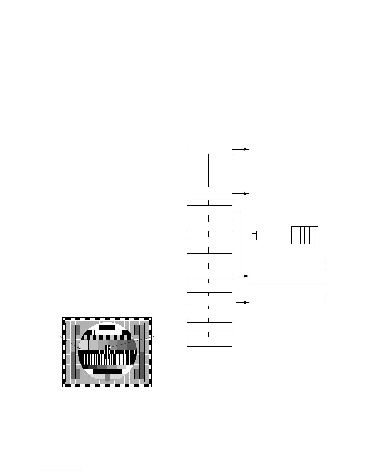
4. Focus Adjustment
4-1. Preparation for Adjustment
Tune the TV set to receive a digital pattern.
4-2. Adjustment Method
1) Adjust the lower Focus volume of FBT for the best focus of
vertical line B.
2) Adjust the upper Focus volume of FBT for the best focus of
area A.
3) Repeat above step 1) and 2) for the best overall focus.
5. Purity & convergence Adjustment
5-1. Preparation for Adjustment
Adjustment should be operated when using the CPT(without
ITC from CPT manufacturing place)
*This adjustment must follow the sequence as shown picture
below.
5-2. Purity Adjustment
1) Degauss the CPT and CABINET enough.
2) Receive red RASTER signal.(PG50ch)
3) Remove fixing screw of DY and stick DY to opening
part(CPT FUNNEL part)
4) Make crossing adjustment to the Magnet of CPT and make
the R-land is placed on center correctly. At this moment, 4
pole and 6 pole magnet should be at the position of no
magnetic field.
- 9 -
ADJUSTMENT INSTRUCTIONS
b
A
B
Fig. 1
Assembling DY to CPT
CPT Assembling
As preparatory operations before
assembling CPT, wind cotton Tape for
protecting to CPT NECK and DY, CPT
connection parts. At this moment, end of
tape should be over-lapped and wound in
direct route to the NECK.
Let the screen Standard condition. Operate
Heat-Run at least 15 minutes.
Torque is to be 9-11 kg f.cm when fixing
DY.
Fix the Magnet to the position as shown
picture below. Be careful not to make CPT
neck shadow while adjusting DY.
HEAT RUN
Degaussing
STC Adjustment
PURITY Adjustment
DY Fixing
SCREEN Voltage adj.
W/B Fixing
FOCUS not yet ADJ.
STC not yet ADJ.
DYC not yet ADJ.
6pole 4 2
2¡ 2mm
5) Move DY and make whole screen to be equal red, and fix
the DY with fixing SCREW after checking color pollution in
each single color and white RASTER of green/blue/red.(At
this time, be careful about inclination and DY should be fixed
keeping horizontality.)
6) Check the receiver in direction of East, West, South, North.
Adjust with supporting MAGNET when adjustment is not
operated.
5-3. Convergence Adjustment
This adjustment should be operated at the best condition of
FOCUS after finishing the PURITY adjustment.
1) BACK RASTER receives black CROSS HATCH signal.
2) Adjust Brightness so that there are 9-12 dots.
3) Widen two tabs of 4pole Magnet with equal angles and
accord red, blue vertical lines at the center of screen.
4) With keeping angle of "c. clause", rotate tab and accord
red/blue, green vertical lines at the center of screen.
5) Widen two tabs of 6pole Magnet with equal angles and
accord red, blue vertical lines at the center of screen.
6) With keeping angle of "e. clause", repeat the adjustment from
c to e keeping in mind the movement of red, blue, green
when the horizontal lines are twisted.
7) Move DY up, down, left, right and make the convergence to
be optimal condition and stick rubber wedge to CPT so that
the DY not to move.
6. Screen voltage Adjustment
6-1. Preparation for Adjustment
1) Connect power to TV Set and let POWER ON condition.
2) Operate screen more than 15 minutes before adjustment.
6-2. Adjustment Method
1) Adjust in no RF signal condition.
2) Press ADJ KEY on the R/C for adjustment and make
horizontal line.
Turn the Screen Volume so that horizontal line not to be
shown and then change oppositely to finish the adjustment
at the showing place.
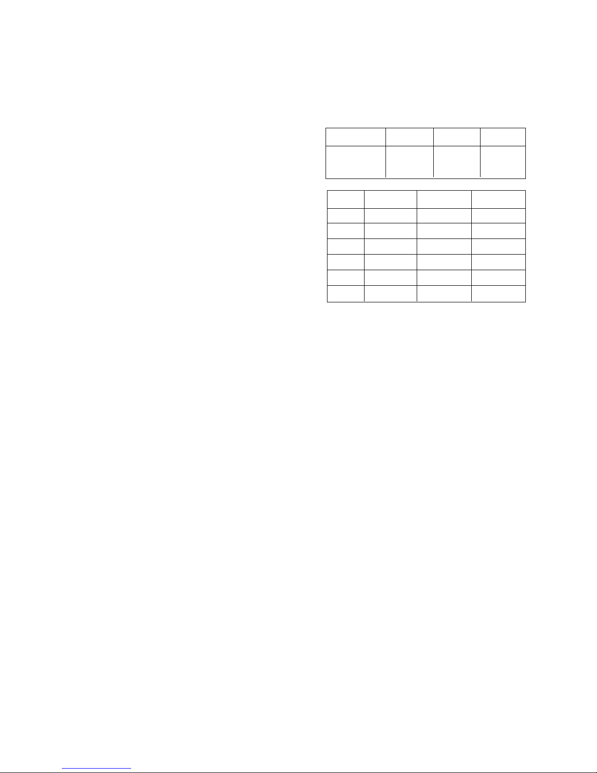
7. White balance Adjustment
7-1. Preparation for Adjustment
1) This adjustment should be performed after screen voltage
adjustment.
2) Tune the TV set to receive an 100% white pattern.
7-2. Adjustment Method
1) Enter the adjust mode by pressing the IN-START button.
2) Press Channel UP/DOWN button for desirous function
Adjustment.
3) Press Volume UP/DOWN button to adjust the data.
4) Adjustment Sequence
a- Change the "CONTRAST", "BRIGHT" and adjust to be 3.5
Ft_L.
b- Adjust "Y" value of High Light with GD(G-Drive) and adjust
"X" value with BD(B-Drive) and make color coordinates
of High Light which is specified in "__clause".
c- Change the "CONTRAST", "BRIGHT" and adjust to be 4.5
Ft_L.
d- Adjust "Y" value of Low Light with GC(G-Cutoff) and
adjust "X" value with BC(B-Cutoff) and make color
coordinates of Low Light which is specified in "__clause".
e- Repeat the adjustment from 'a' to 'd' until the High, Low
color coordinates of "_clause" is satisfied.
f- Check the adjusted color coordinates with white balance
meter.
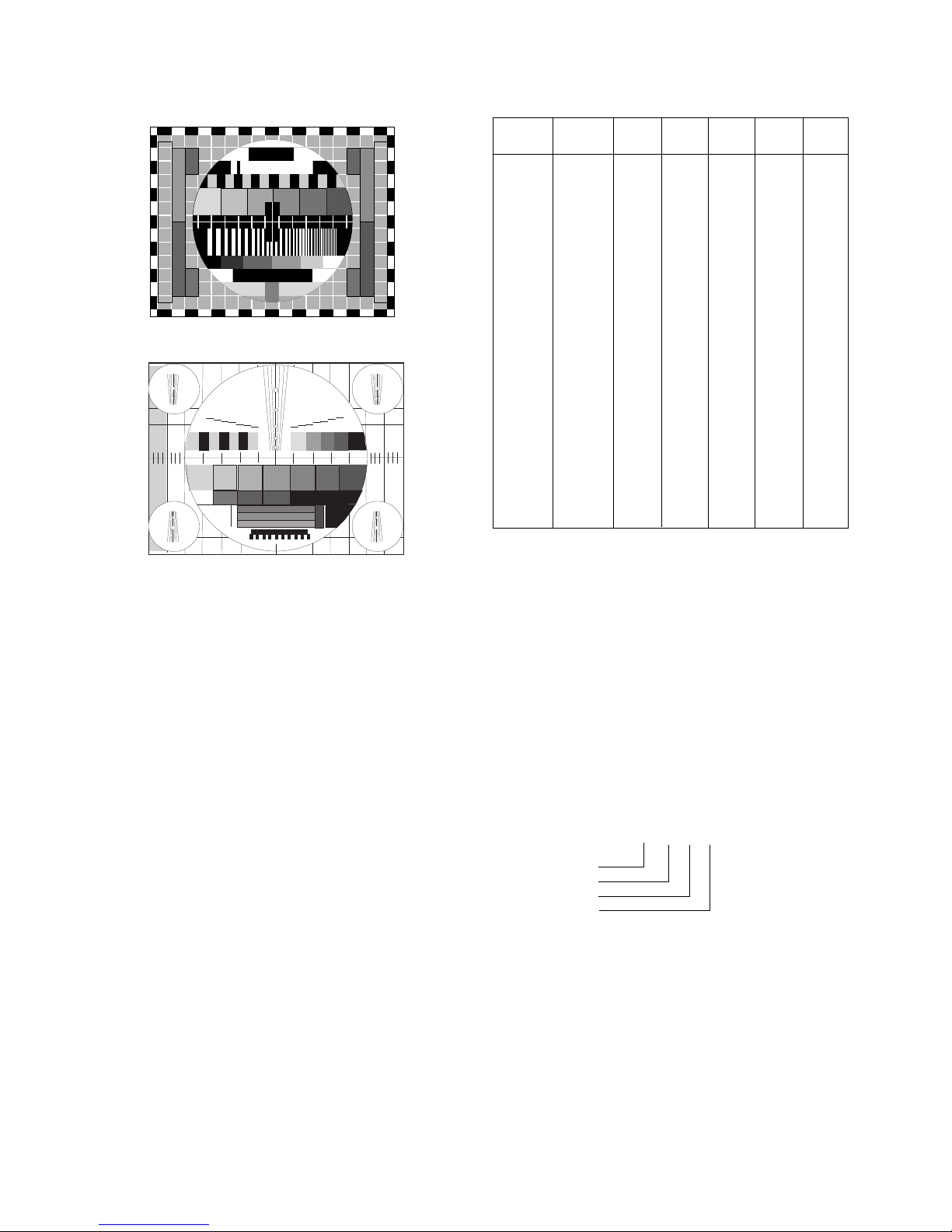
8. Deflection Data Adjustment
8-1. Preparation for Adjustment
1) Deflection Data Adjustment should be performed with the
remote controller for handset.
2) Enter the Adjustment mode by pressing the INSTART button.
3) Select the DEFLECT to deflection Data Adjustment.
4) Press the Channel UP/DOWN button to select adjustment
items.
5) Press the Volume UP/DOWN button to adjust the data.
6) The TV set receives PAL-B/G Digital pattern.
NOTE : If production line doesn’t the production line of LG
TV,receive available deflection adjustment pattern.
VL (Vertical Linearity)
Adjust so that the boundary line between upper and lower half
is in accord with geometric horizontal center of the CPT.
VA (Vertical Amplitude)
Adjust so that the circle of a digital circle pattern may be
located within the effective screen of the CPT.
SC (Vertical “S” Correction)
Adjust so that all distance between each horizontal lines are
to be the same.
VS--(Vertical Shift)
Adjust so that the horizontal center line of a digital circle pattern
is in accord with geometric horizontal center of the CPT.
HS (Horizontal Shift)
Adjust so that the vertical center line of a digital circle pattern
is in accord with geometric vertical center of the CPT.
EW (Horizontal Width)
Adjust to that a digital circle pattern looks like exact circle.
- 10 -
Color Tem.
13000K
9000K
266
!
8
288!
8
273!
8
295!
8
NON EU
EU
X
Y
Memo
Menu
RC
GC
BC
RD
GD
BD
001F
0019
001F
001F
0019
001F
Low Light Adj
Low Light Adj
Low Light Adj
High Light Adj
High Light Adj
High Light Adj
LG 29” FLAT
MENO
- 11 -
EPP(East-West Pin Phase)
Adjust so that horizontal width of the uppermost part and
horizontal width of the lowermost part of received screen are
to be the same.
UC(Upper Coner Correction)
Adjust so that coner vertical line of upper-left and upper-right
to be straight line after finishing EP adjustment.
LC(Lower Coner Correction)
Adjust so that coner vertical line of lower-left and lower-right
to be straight line after finishing EP adjustment.
A-BOW(AFC Bow)
In line adjustment, not to change default value is basic.
A-ANG(AFC Angle)
In angle adjustment, adjust until inclination of left and right
screen should be precise.
V-SCR(V-Scroll)
Only adjust when V SHIFT is impossible.
* Adjust in PAL100Hz and PAL50Hz, NTSC60Hz, 480P, 1080I,
VGA Mode don't need to be adjusted because they are changed
into correction about adjustment value of PAL 100Hz.
* But, If the inclination adjustment is not correct when checking
NTSC60Hz, 480P, 1080I, VGA Mode after finishing adjustment in
PAL100Hz, adjust each Mode again.
9.
OPTION Adjustment
9-1. Preparation for Adjustment
1) This decides function in accordance with model.
Press the SVC TX adjustment button(IN-START button) at
SVC mode,then adjust the option at OPTION 1,2,3,4 mode.
2) Mark the option adjustment data like [111,11,111,11] in
BOM.
Menu
VS
VA
HS
EW
EP
EPP
A-ANG
A-BOW
UC
LC
U-VL
L-VL
VL
SC
V-SCR
0 ~ 3F
0 ~ 3F
0 ~ 3F
0 ~ 3F
0 ~ 3F
0 ~ 3F
0 ~ 3F
0 ~ 3F
0 ~ 3F
0 ~ 3F
0 ~ 0F
0 ~ 0F
0 ~ 0F
0 ~ 0F
0 ~ 3F
1E
1E
1C
1D
A
1E
1F
1E
1F
1F
02
06
05
05
21
18
1F
29
1D
C
1D
1F
20
21
22
2
7
5
4
21
17
1E
14
1F
B
1B
1D
1E
20
20
2
7
5
4
21
11
23
25
2A
E
14
1D
1E
20
1F
2
7
5
4
21
1D
2B
10
1C
7
22
21
1E
1C
15
2
6
5
4
21
Range
PAL
100HZ
NTSC
60HZ
480P 1080I VGA
Fig. 2 <50HZ>
Fig. 2<60HZ>
[113,63,112,128]
OPTION 1
OPTION 2
OPTION 3
OPTION 4
D D D D
O Mark of BOM
LEVEL PART NO. SPECIFICATION DESCRIPTION JOB EXP.
1. 3141VMN382A MAIN[MC-022A] CHASSIS ASSY OP[113,63,112,128]
The OPTION 1 data is 113,OPTION 2 data is 63,the oOPTION 3 data is 112,the
OPTION 4 data is 128 in this model.
 Loading...