

LG RT-29FD15VE, RT-29FD15RB, RT-29FD15VX, RT-29FD16RX, RT-29FD15RK Service Manual
...
COLOR TV
SERVICE MANUAL
CAUTION
BEFORE SERVICING THE CHASSIS,
READ THE SAFETY PRECAUTIONS IN THIS MANUAL.
CHASSIS : MC-049A
MODEL:RT-29FD15R/RB/RE/RK
MODEL:RT-29FD15RQ/V/VE/VX
MODEL:RT-29FD16RX
website:http://biz.LGservice.com
e-mail:http://www.LGEservice.com/techsup.html

- 2 -
CONTENTS
Contents...................................................................................................................2
Safety Precautions..............................................................................................3
Control Descriptions..........................................................................................4
Specifications........................................................................................................7
Adjustment Instructions .................................................................................8
Trouble Shooting.................................................................................................12
Printed circuit board.........................................................................................16
Block Diagram ......................................................................................................18
Exploded View....................................................................................................20
Exploded View Parts List ..............................................................................21
Replacement Parts List .................................................................................22
SVC. Sheet..................................................................................................................
- 3 -
SAFETY PRECAUTIONS
Many electrical and mechanical parts in this chassis have special safety-related characteristics. These parts are identified by in
the Schematic Diagram and Replacement Parts List.
It is essential that these special safety parts should be replaced with the same components as recommended in this manual to
prevent X-RADIATION, Shock, Fire, or other Hazards.
Do not modify the original design without permission of manufacturer.
General Guidance
An isolation Transformer should always be used during
the servicing of a receiver whose chassis is not isolated from
the AC power line. Use a transformer of adequate power rating
as this protects the technician from accidents resulting in
personal injury from electrical shocks.
It will also protect the receiver and it's components from being
damaged by accidental shorts of the circuitry that may be
inadvertently introduced during the service operation.
If any fuse (or Fusible Resistor) in this TV receiver is blown,
replace it with the specified.
When replacing a high wattage resistor (Oxide Metal Film
Resistor, over 1W), keep the resistor 10mm away from PCB.
Keep wires away from high voltage or high temperature parts.
Due to high vacuum and large surface area of picture tube,
extreme care should be used in handling the Picture Tube.
Do not lift the Picture tube by it's Neck.
X-RAY Radiation
Warning:
To determine the presence of high voltage, use an accurate
high impedance HV meter.
Adjust brightness, color, contrast controls to minimum.
Measure the high voltage.
The meter reading should indicate
23.5
¡ 1.5KV: 14-19 inch, 26 ¡ 1.5KV: 19-21 inch,
29.0 ¡ 1.5KV: 25-29 inch, 30.0 ¡ 1.5KV: 32 inch
If the meter indication is out of tolerance, immediate service
and correction is required to prevent the possibility of
premature component failure.
Before returning the receiver to the customer,
always perform an AC leakage current check on the exposed
metallic parts of the cabinet, such as antennas, terminals, etc.,
to be sure the set is safe to operate without damage of
electrical shock.
Leakage Current Cold Check(Antenna Cold Check)
With the instrument AC plug removed from AC source,
connect an electrical jumper across the two AC plug prongs.
Place the AC switch in the on position, connect one lead of
ohm-meter to the AC plug prongs tied together and touch other
ohm-meter lead in turn to each exposed metallic parts such as
antenna terminals, phone jacks, etc.
If the exposed metallic part has a return path to the chassis, the
measured resistance should be between 1MΩ and 5.2MΩ.
When the exposed metal has no return path to the chassis the
reading must be infinite.
An other abnormality exists that must be corrected before the
receiver is returned to the customer.
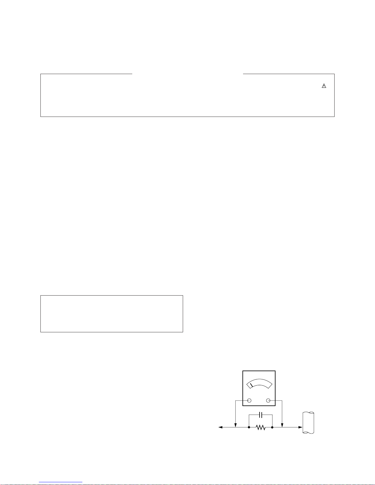
Leakage Current Hot Check (See below Figure)
Plug the AC cord directly into the AC outlet.
Do not use a line Isolation Transformer during this check.
Connect 1.5K/10watt resistor in parallel with a 0.15uF capacitor
between a known good earth ground (Water Pipe, Conduit, etc.)
and the exposed metallic parts.
Measure the AC voltage across the resistor using AC
voltmeter with 1000 ohms/volt or more sensitivity.
Reverse plug the AC cord into the AC outlet and repeat AC
voltage measurements for each exposed metallic part. Any
voltage measured must not exceed 0.75 volt RMS which is
corresponds to 0.5mA.
In case any measurement is out of the limits specified, there is
possibility of shock hazard and the set must be checked and
repaired before it is returned to the customer.
Leakage Current Hot Check circuit
The source of X-RAY RADIATION in this TV receiver is the
High Voltage Section and the Picture Tube.
For continued X-RAY RADIATION protection, the
replacement tube must be the same type tube as specified in
the Replacement Parts List.
1.5 Kohm/10W
To Instrument's
exposed
METALLIC PARTS
Good Earth Ground
such as WATER PIPE,
CONDUIT etc.
AC Volt-meter
IMPORTANT SAFETY NOTICE
0.15uF
- 4 -
DESCRIPTION OF CONTROLS
All the functions can be controlled with the remote control handset.
Some functions can also be adjusted with the buttons on the front
panel of the set.
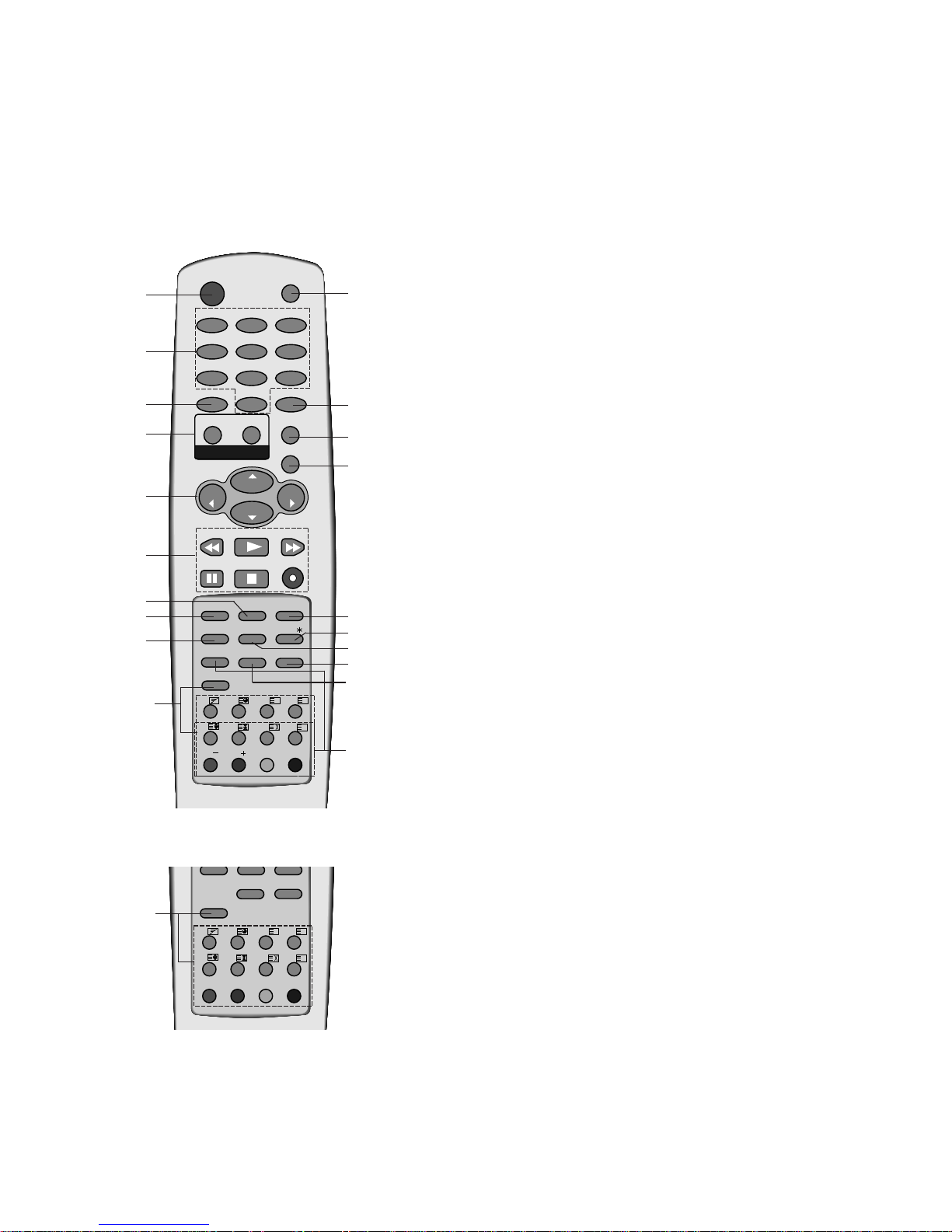
Remote control handset
Before you use the remote control handset, please install the batteries. See the next page.
1. POWER
switches the set on from standby or off to standby.
2. NUMBER BUTTONS
switches the set on from standby or directly select a number.
3. ARC (Aspect Ratio Control)
changes the picture format.
4. TURBO PICTURE / SOUND BUTTON
selects Turbo picture / sound.
5.D / E(Programme Up/Down)
selects a programme or a menu item.
switches the set on from standby.
F / G
(Volume Up/Down)
adjusts the volume.
adjusts menu settings.
6. VCR BUTTONS (option)
control a LG video cassette recorder.
7. SSM (Sound Status Memory)
recalls your preferred sound setting.
8. I/II (option)
selects the language during dual language broadcast (option).
selects the sound output.
9. PSM (Picture Status Memory)
recalls your preferred picture setting.
10. TELETEXT BUTTONS (option)
These buttons are used for teletext.
For further details, see the ÔTeletextÕ section.
11. MUTE
switches the sound on or off.
12. TV/AV
selects TV or AV mode.
switches the set on from standby.
13. MENU
selects a menu.
14. OK
accepts your selection or displays the current mode.
OK
PR
VOL
PR
VOL
PLAY
P/STILL STOP
REC
REW
FF
I/II SSM LIST
PSM
SLEEP
PIP
Q.VIEW
?
MIX
TIME
SWAP
INPUT
REVEAL MODE
SIZE
STILL
POSITION
9/4 PIP
i
M
0
ARC
TV/AV
MENU
PICTURE
SOUND
1
2 3
4
5 6
7
8 9
POWER
MUTE
TEXT
PR
PR
T U R B O
EYE/
FAVOURITE
TEXT
Q.VIEW
?
MIX
TIME
REVEAL MODE
SIZE
HOLD
UPDATE
INDEX
i
M
FAVOURITE
(With TELETEXT / Without PIP)
(With TELETEXT / PIP)
2
1
3
5
6
8
4
9
7
11
12
15
16
13
18
14
17
20
10
19
10
- 5 -
OK
PR
VOL
PR
VOL
PLAY
P/STILL STOP
REC
REW
FF
I/II SSM LIST
PSM
SLEEP
Q.VIEW
0
ARC
TV/AV
MENU
PICTURE
SOUND
1
2 3
4
5 6
7
8 9
POWER
MUTE
T U R B O
EYE/
FAVOURITE
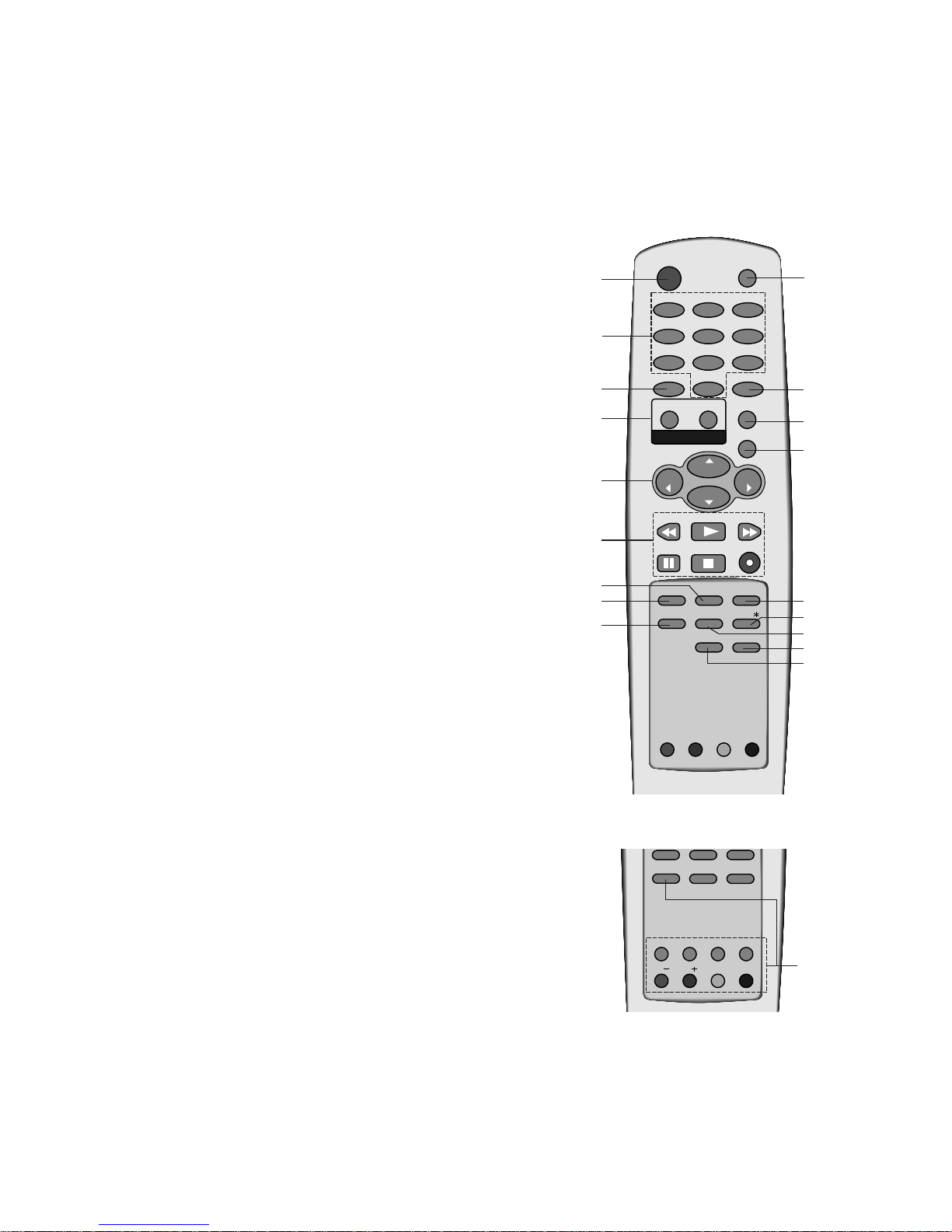
15. LIST
displays the programme table.
16. EYE/*(option)
switches the eye function on or off.
17. SLEEP
sets the sleep timer.
18. Q.VIEW
returns to the previously viewed programme.
19. FAVOURITE
selects a favorite programme.
20. PIP BUTTONS (option)
PIP
switches the sub picture on or off.
PR +/-
selects a programme for the sub picture.
SWAP
alternates between main and sub picture.
INPUT
selects the input mode for the sub picture.
SIZE
adjusts the sub picture size.
STILL
freezes motion of the sub picture.
POSITION
relocates the sub picture in clockwise direction.
9/4 PIP
switches on or off the programme scan mode through 4 or 9
sub pictures.
COLOURED BUTTONS
These buttons are used for teletext (only TELETEXT models) or
programme edit.
FAVOURITE
Q.VIEW
SWAP
INPUT
SIZE
STILL
POSITION
9/4 PIP
PR
PR
EYE/
PIP
(Without TELETEXT / With PIP)
(Without TELETEXT / PIP)
2
1
3
5
6
8
4
9
7
11
12
15
16
13
18
14
17
19
20

- 6 -
1. MAIN POWER
switches the set on or off.
2. POWER/STANDBY INDICATOR
illuminates brightly when the set is in
standby mode.
dims when the set is switched on.
3. MENU
selects a menu.
4. OK
accepts your selection or displays the
current mode.
5.
DD / EE
(Programme Up/Down)
selects a programme or a menu item.
switches the set on from standby.
FF / GG
(Volume Down/Up)
adjusts the volume.
adjusts menu settings.
6. REMOTE CONTROL SENSOR
Note : Only use the supplied remote
control handset. (When you use others,
theyÕll be not able to function.)
7. TV/AV
selects TV or AV mode.
clears the menu from the screen.
switches the set on from standby.
8. (Function)
selects volume, EYE (option), picture items
or brief auto programme while the menus
not display.
9. +/- (
DD/EE
)
adjusts the function or selects a programme.
switches the set on from standby.
10. TURBO SOUND / PICTURE (option)
switches Turbo sound or Turbo picture
function on or off.
11. EYE (option)
adjusts picture according to the surrounding conditions.
12. HEADPHONE SOCKET (option)
Connect the headphone plug to this
socket.
13. AUDIO/VIDEO IN SOCKETS (AV3)
Connect the audio/video out sockets of
external equipment to these sockets.
S-VIDEO/AUDIO IN SOCKETS (S-AV)
(option)
Connect the video out socket of an SVIDEO VCR to the S-VIDEO socket.
Connect the audio out sockets of the SVIDEO VCR to the audio sockets as in
AV3.
Note : Do not place any heavy objects
(over 4Kg) on the RT-25/29FA35 series
models.
ON/OFF
TV/AV
AV3
VIDEO AUDIO
VOL
PR
L/MONO R
CF/CT-25/29K35 series
1
2
6
7
8
9 13
11
S-VIDEO
VIDEO
L/MONO RAUDIO
AV3
12
13
ON/OFF
MENU OK VOL PR
RF/RT-25/29CA45 series
1
2
6
11
5
3
4
ON/OFF
MENU
O K
VOL VOL
PR
CF/CT-25/29Q45 series
1
3
2 6
4
11
5
12
CF/CT-25/29M35 series
1
2 6 7 8 9
VIDEO
AUDIO
L
R
MONO
AV3
12
13
L/MONO R
AUDIO
VIDEO
AV3
S-VIDEO
12
13
ON/OFF
MENU
VOL SOUN D
OK
PR PICTURE
TURBO
CF/CT-25/29Q95 series
1
2
6 54 10
11
3
S-VIDEO
VIDEO
L/MONO RAUDIO
AV3
12
13
ON/OFF
MENU
OK
VOL PR
VIDEO
AUDIO
L
R
AV
RF/RT-25/29FB55 series
2 6 34 125 13
1
11
RF/RT-25/29FB75 series
1
2 6 3 4 5
RF/RT-25/29FD15 series
MENU OK
VOL
PR
1 2 6 43 5

- 7 -
SPECIFICATIONS
Note : Specification and others are subject to change without notice for improvement.
F Scope
This specification can be applied to all the television related to
MC-049A Chassis.
F Test and Inspection Method
1) performance:Follow the Standard of LG TV test
2) Standards of Etc. requirement
- Safety: IEC60065
- EMC: EN55020,EN55013
F Test Condition
1) Temperature :20 ± 5¡C(CST : 40 ± 5¡C)
2) Relative Humidity:65
± 10%
3) Use the parts only designated in B.O.M.,PARTS SPEC.,or
drawings.
4) Follow each drawing or spec for spec and performance of
parts,based upon P/N of B.O.M
5) Warm up TV set for more than 20min. before the
measurement.
Standard input Voltage
110-240V~, 50/60Hz
230V~, 50/60Hz
Market
Middle East, Africa
EU
Chassis
MC049A
Brand
LG
No
1
2
3
4
5
6
7
8
Item
Receiving System
Available Channel
Input Voltage
Market
Screen Size
Tuning System
Operating Environment
Storage Environment
Remark
For EU/ For Non EU
OPTION
Non EU
EU
200 PR. (W/O TXT)
Specification
PAL,SECAM BG
PAL/SECAM DK
PAL-I/I
NTSC M
NTSC 4.43(AV)
SECAM-L/LÕ
NTSC M/ PAL M/N
VHF : E2 ~ E12
UHF : E21 ~ E69
CATV : S1 ~ S20
HYPER : S21 ~ S41
110-240V~, 50/60Hz
230V~, 50/60Hz
EU,CIS, China, Asia, Africa
Flat 25Ó, 29Ó, 28Ó, 32Ó
NOR 25Ó, 27Ó, 28Ó, 29Ó
FVS 100Program
1) Temp : 0 ~ 45 deg
2) Humidity: 85% under
1) Temp : -20 ~ 60 deg
2) Humidity: 85% under
F General Specification

1. Application Object
These instructions are applied to all of the color TV, MC-049A.
2. Notes
(1) Because this is not a hot chassis, it is not necessary to use
an isolation transformer. However, the use of isolation
transformer will help protect test instrument.
(2) Adjustment must be done in the correct order.But the
adjustment can be changed by consideration of mass
production.
(3) The adjustment must be performed in the circumstance of
25±5¡C of temperature and 65±10% of relative humidity if
there is no specific designation.
(4) The input AC voltage of the receiver must keep rating
voltage in adjusting.
(5) The receiver must be operated for about 15 minutes prior
to the adjustment.
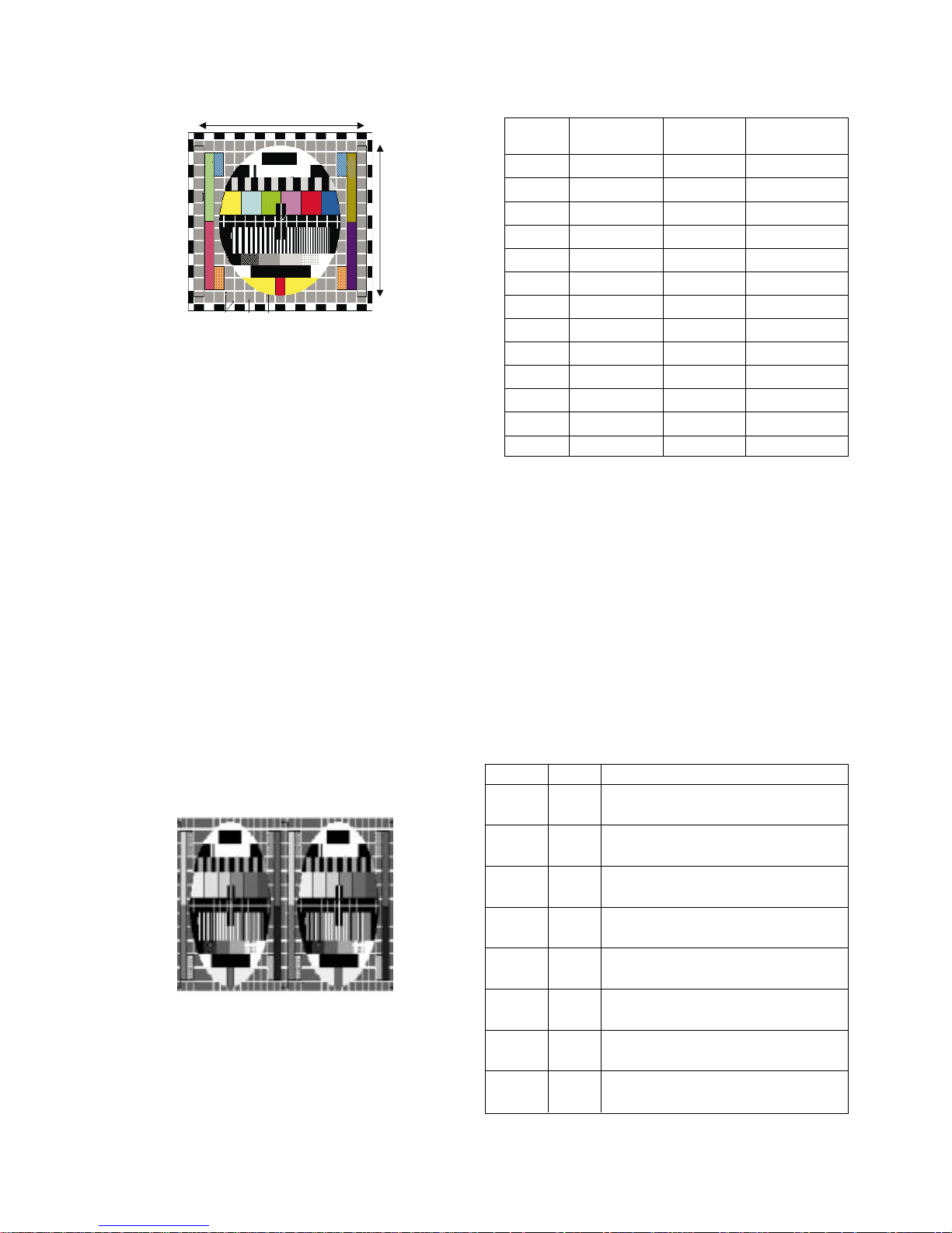
3. Focus adjustment
3.1. Preliminary steps
Tune the TV set to receive a digital pattern.
(SVC mode:Automatically mode change the STANDARD
MODE)
3.2. Adjustment Method
1) Single Focus CPT
Adjust the upper Focus volume of FBT for the best focus of
horizontal line A,vertical line B.
2) Double Focus CPT
a) Adjust the lower Focus volume of FBT for the best focus
of vertical line B.
b) Adjust the upper Focus volume of FBT for the best focus
of area A.
c) Repeat above step 1) and 2) for the best overall focus.
4. Purity & Convergence adjustment
4.1. Color purity adjustment
(1) It makes CPT or CABINET enough to demagnetization.
(2) Receive the signal of red raster.
(3) Loosen fixed screw of DY and closely to CPT funnel part.
(4) Check the center of screen that PURITY MAGNET of CPT
by crossing adjustment. At this time, 4 & 6 pole magnet is
located to magnet of nothing.
(5) Move the DY to make equal red on whole screen and it
does not to make the DY by fixed screw after check a
simple color of Red/Green/Blue and white raster whether or
not it is a pollution of color.
(At this time, take care raster of screen and DY must fixing
in the condition which maintains a horizontality.)
(6) Check the TV set by move direction.
4.2. Convergence adjustment
These adjustments can the best condition of focus after
finished purity adjustment.
(1) Receive the signal of cross hatch that BACK RASTER is
black.
(2) Adjust brightness and luminosity till dot appear 9 ~12.
(3) Open angle of the two tab of 4 pole MAGNET by isogonic
angle and accord with vertical line of red and blue color in
the middle of screen.
(4) Maintain as angle of (3) and rotate the tab to accord with
vertical line of Red and Blue color in the middle of screen.
- 8 -
ADJUSTMENT INSTRUCTIONS
A
B
<Fig 1. PAL Digital Pattern(EU05CH)>
Assembling DY to
CPT
CPT Assembling
As preparatory operations before
assembling CPT, wind cotton Tape for
protecting to CPT NECK and DY, CPT
connection parts. At this moment, end
of tape should be over-lapped and
wound in direct route to the NECK.
Let the screen Standard condition.
Operate Heat-Run at least 15
minutes.
Torque is to be 9-11 kg f.cm when
fixing DY.
Fix the Magnet to the position as
shown picture below. Be careful not to
make CPT neck shadow while
adjusting DY.
HEAT RUN
Degaussing
STC Adjustment
PURITY Adjustment
DY Fixing
SCREEN Voltage adj.
W/B Fixing
FOCUS not yet ADJ.
STC not yet ADJ.
DYC not yet ADJ.
Convergence Magnet
15 ~ 20mm
¢‚
¢‚
6Pole
4
2

(5) Open angle of the two tab of 6 pole magnet by isogonic
angle and accord with vertical line of Red/Blue and Green.
(6) Maintain as angle of (5) and rotate the tab to accord with
horizontal line. In case of twisted horizontal line,repeat
adjustment of (3) ~ (5) remembering the movement of
Red/Green/Blue color.
(7) Move the DY to best condition of convergence and attach
the CPT to a rubber-chock for fixed DY.
5. Screen voltage adjustment
(1) Receive the PAL or SECAM(NTSC) signal into RF mode
regardless of channel.
(2) If you press the ÒADJÓbutton in LINE SVC mode(IN-START
button),the LINE SVC mode changes to screen adjustment
mode.
(3) Turn the Screen Volume of FBT to change luminance of
White signal center as shown below.
(4) Press the EXIT TV/AV button to exit SVC mode.
6. White balance adjustment
NOTE : When adjusting white balance automatically,connect the
adjustment JIG in SVC mode.(When pressing INSTART,MUTE button on remote control for adjustment
orderly,it changes to SVC mode and screen displays
ÒCUT OFFÓ.)
(1) Receive 100% white pattern.
(2) Adjust LOW LIght status(4.5FL) of CUT R,CUT B at
CG:70.
(3) Adjust HIGH LIght status(35FL) of WDR R,WDR B at
WDR G:380.
(4) Repeat above step (2) and (3) for the best condition each
status of High Light and Low Light.
<CAUTION> W/B Program ÒTwbeng_v2.0Ó
- W/B adjustment after Cutoff
: Instart -> adj. -> mute(cutoff)-> tv/av(wb)
Release key is EXIT key
- W/B adjustment
: Instart -> mute(cpuoff) ->
Release key is TV/AV key
7.Deflection setting Data Adjustment
7.1 Adjustment preparation
(1) Tune the TV set to receive an Digital pattern(EU05CH).
(2) Deflection setting data adjustment is operate by SVC
communicator.
(3) Enter the deflection mode by selection SERVICE1 key on
SERVICE MENU after enter the adjustment mode by
pressing LINE SVC MODE(IN-START KEY).
(4) Enter the deflection mode by pressing ADJUST key.
(5) Use the CH D ,E key to select adjustment item.
(6) Use the VOL F ,G key to increase/decrease data.
<Note>
(1) When adjusting a deflection,adjust N50Hz of PAL signal first and
adjust a deflection at Normal 60Hz(NTSC).
(2) Adjust a deflection as shown below.
PAL 4:3 -> NTSC 4:3
(3) After finishing deflection adjustment,press the EXIT key to
exit in adjustment mode.
(4) Wide Models
After adjusting 16:9(50Hz), Readjust 14:9(50Hz) ->
ZOOM(50Hz) -> 4:3(50Hz) -> 16:9(60Hz) -> 14:9(60Hz) ->
ZOOM(60Hz) -> 4:3(60Hz).
7.2 Adjustment
(1) VL(Vertical Linearity) adjustment:
Adjust the top & bottom size of inner circle to be equal.
(2) VA (Vertical Amplitude) adjustment:
Adjust so that the circle of a digital circle pattern should be
located interval of 6~7mm from the effective screen of the
CPT.
(3) SC (Vertical S correction) adjustment:
Adjust so that all distance between each lattice width of
top/center/bottom are to be the same.
2. White balance IIC Parameter
Program
Sub Add
Start Bit
Stop Bit
Offset
Polarity
EP_Rom_S
R_Amp
TWBeng2.0
1C8
12
4
0
1
7A7B
R_Cut
TWBeng2.0
1C3
12
4
0
1
7475
B_Amp
TWBeng2.0
1CA
12
4
0
1
7E7F
- 9 -
Menu
X
Y
Color Temperature
288
295
9000
o
K
268
273
13000
o
K
EU
N-EU
<Table 1> White Balance Color analyzer
Menu
CR
CG
CB
WR
WG
WB
LOW LIGHT
HIGH LIGHT
0 ~ 511
0 ~ 511
0 ~ 511
0 ~ 511
0 ~ 511
0 ~ 511
70
70
70
430
380
430
Range
DATA
<Table 2> White Balance Initial Data
<Table 3> White Balance Initial Data
1. IC
VCD IC
EP_ROM
VCT48xyi
24C16
Micronas
ST, ATMEL
0 F 0 0
Name
Maker Algorithm
Program
Vcd Slave
TWBeng2.0
24C16
Program
Eprom_Slave
TWBeng2.0AESpeed1Delay
30
B_Cut
TWBeng2.0
1C5
12
4
0
1
7879
Speed/ Plus 1 1 1 1
(4) VS (Vertical Shift) adjustment:
Adjust so that the geometric vertical center line is in accord
with vertical center line of CPT.
(5) HS(Horizontal Shift) adjustment:
Adjust so that the geometric horizontal center line is in
accord with horizontal center line of CPT.
(6) EW(East-West Width) adjustment:
Adjust until the outmost left and right lattice of received
pattern is accord with 25% of other lattice width.
(7) ET(Trapezoidal) adjustment:
Adjust to make the length of top horizontal line same with it
of the bottom horizontal line.
(8) EP(Pin Cushion) adjustment:
Adjust so that middle portion of the outermost left and right
vertical line look like parallel with vertical lines of the CPT.
(9) ANGLE adjustment
When you adjust the angle, adjust correctly raster of
left/right screen.
(10) BOW adjustment
A standard is not changing the default value.
(11) CRNU(Upper Corner Correction) adjustment:
After finished EP adjustment,adjust vertical line of lefttop,right-top of screen to the best straight line.
(12) CRNL(Lower Corner Correction) adjustment:
After finished EP adjustment,adjust vertical line of leftbottom ,right-bottom of screen to the best straight line.
(13) PIP(PIP Position)
Adjust until the distance between PIP and main picture
becomes about 1~2mm by using VOL +/- key.
8.
OPTION Adjustment
8-1. Preparation for Adjustment
1) This option adjustment decides function in accordance with
model. Press the SVC TX adjustment button(IN-START
button) at SVC mode, then adjust the option at OPTION1
mode.
2) Mark the option adjustment data like [111,111,111,111] in
BOM.
8-2. Adjustment Method
OPTION data input
1) Function : 1, No function : 0
2) Select each OPTION function by the CH Up/Down
button and then set up each OPTION by the VOL
Up/Down button at OPTION 1,2,3,4.
8-3. OPTION Function
- 10 -
<Fig. 2>PAL Digital pattern (EU05CH)
<Fig. 3> PIP H Position
Menu
VS
VA
VL
SC
HS
EW
ET
EP
ANGLE
BOW
UPCOR
LOCOR
PIP_H
-512~511
-512~511
-512~511
-512~511
32~2047
-256~255
-512~511
-512~511
-512~511
-512~511
-512~511
-512~511
0~40
4
80
-70
140
110
-70
-12
-80
0
0
8
20
15
10
70
-70
140
130
-69
-15
-78
0
0
8
20
15
Variable range
N50Hz(PAL)
29Ó
N60Hz(NTSC)
29Ó
AV3
S-VIDEO
DVD
SCART
WIDE
GAME
21inch
A2ST
Option Code
0
1
0
1
0
1
0
1
0
1
0
1
0
1
0
1
Function
Without A/V3
With AV3
With out S-VIDEO
With S-VIDEO
Without COMPONENT(480i)
With COMPONENT(480i)
PHONE JACK
SCART JACK
Not WIDE MODEL
WIDE MODEL
Without GAME function
With GAME function
Not 21inch MODEL
21inch MODEL
NICAM
NICAM & FM STEREO
 Loading...