

LG RT-29FA30V, RT-29FA30RX, RT-29FA30RU Service Manual

COLOR TV
SERVICE MANUAL
CAUTION
BEFORE SERVICING THE CHASSIS,
READ THE SAFETY PRECAUTIONS IN THIS MANUAL.
CHASSIS : MC-007C
MODEL:RT-29FA30V/RX/RU
website:http://biz.LGservice.com
e-mail:http://www.LGEservice.com/techsup.html

- 2 -
CONTENTS
Contents ................................................................................................................. 2
Safety Precautions ............................................................................................3
Specifications ..................................................................................................... 4
Control Descriptions ........................................................................................ 5
Disassembly Instructions ............................................................................. 8
Adjustment Instructions ............................................................................... 9
Exploded View .................................................................................................. 24
Exploded View Parts List .............................................................................25
Replacement Parts List ............................................................................... 26
SVC. Sheet ................................................................................................................
- 3 -
SAFETY PRECAUTIONS
Many electrical and mechanical parts in this chassis have special safety-related characteristics. These parts are identified by in
the Schematic Diagram and Replacement Parts List.
It is essential that these special safety parts should be replaced with the same components as recommended in this manual to
prevent X-RADIATION, Shock, Fire, or other Hazards.
Do not modify the original design without permission of manufacturer.
General Guidance
An lsolation Transformer should always be used during
the servicing of a receiver whose chassis is not isolated from
the AC power line. Use a transformer of adequate power rating
as this protects the technician from accidents resulting in
personal injury from electrical shocks.
It will also protect the receiver and it's components from being
damaged by accidental shorts of the circuitary that may be
inadvertently introduced during the service operation.
If any fuse (or Fusible Resistor) in this TV receiver is blown,
replace it with the specified.
When replacing a high wattage resistor (Oxide Metal Film
Resistor, over 1W), keep the resistor 10mm away from PCB.
Keep wires away from high voltage or high temperature parts.
Due to high vacuum and large surface area of picture tube,
extreme care should be used in handling the Picture Tube.
Do not lift the Picture tube by it's Neck.
X-RAY Radiation
Warning:
To determine the presence of high voltage, use an accurate
high impedance HV meter.
Adjust brightness, color, contrast controls to minimum.
Measure the high voltage.
The meter reading should indicate
23.5 ± 1.5KV: 14-19 inch, 26 ± 1.5KV: 19-21 inch,
29.0 ± 1.5KV: 25-29 inch, 30.0 ± 1.5KV: 32 inch
If the meter indication is out of tolerance, immediate service
and correction is required to prevent the possibility of
premature component failure.
Before returning the receiver to the customer,
always perform an AC leakage current check on the exposed
metallic parts of the cabinet, such as antennas, terminals, etc.,
to be sure the set is safe to operate without damage of
electrical shock.
Leakage Current Cold Check(Antenna Cold Check)
With the instrument AC plug removed from AC source,
connect an electrical jumper across the two AC plug prongs.
Place the AC switch in the on positioin, connect one lead of
ohm-meter to the AC plug prongs tied together and touch other
ohm-meter lead in turn to each exposed metallic parts such as
antenna terminals, phone jacks, etc.
If the exposed metallic part has a return path to the chassis, the
measured resistance should be between 1MΩ and 5.2MΩ.
When the exposed metal has no return path to the chassis the
reading must be infinite.
An other abnormality exists that must be corrected before the
receiver is returned to the customer.
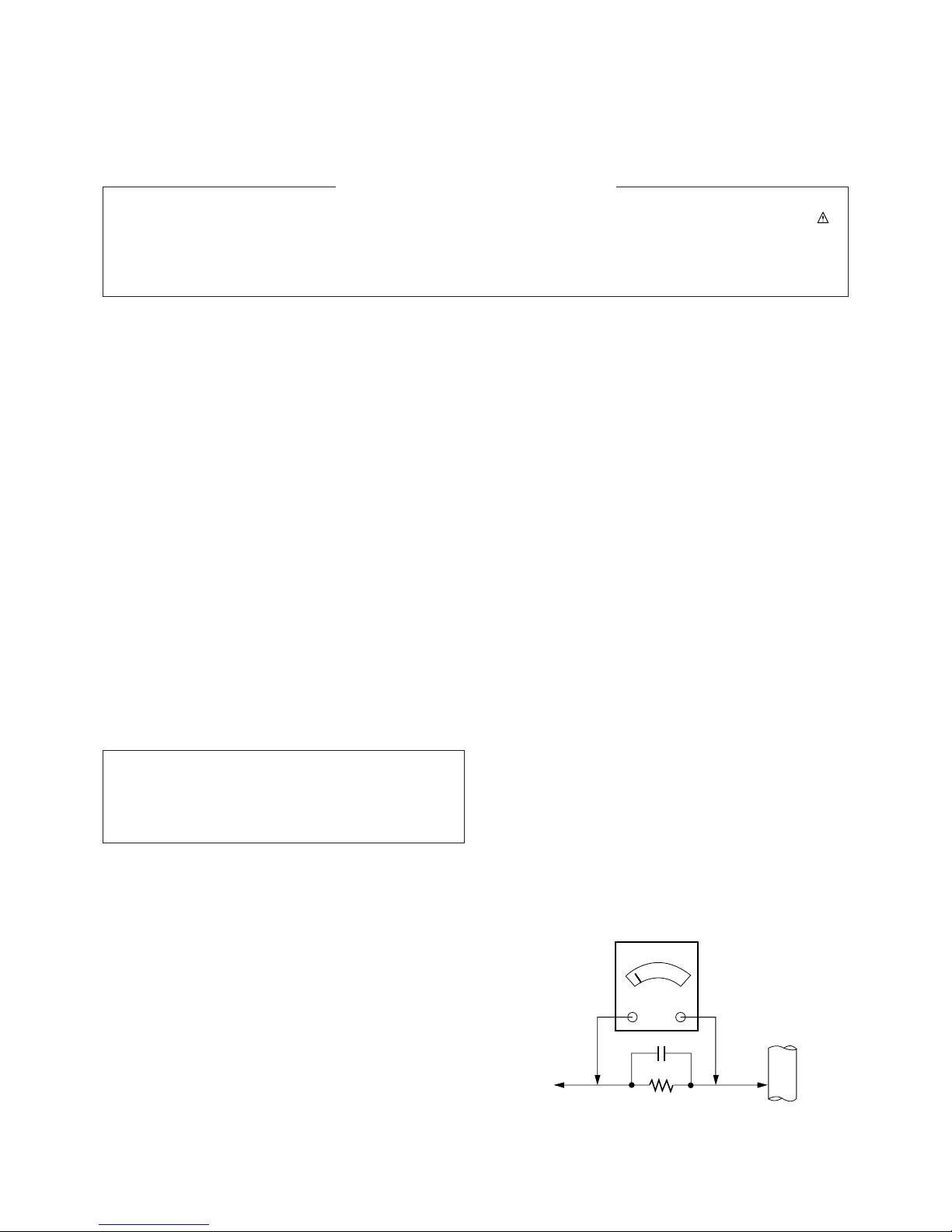
Leakage Current Hot Check (See below Figure)
Plug the AC cord directly into the AC outlet.
Do not use a line Isolation Transformer during this check.
Connect 1.5K/10watt resistor in parallel with a 0.15uF capacitor
between a known good earth ground (Water Pipe, Conduit, etc.)
and the exposed metallic parts.
Measure the AC voltage across the resistor using AC
voltmeter with 1000 ohms/volt or more sensitivity.
Reverse plug the AC cord into the AC outlet and repeat AC
voltage measurements for each esposed metallic part. Any
voltage measured must not exceed 0.75 volt RMS which is
corresponds to 0.5mA.
In case any measurement is out of the limits sepcified, there is
possibility of shock hazard and the set must be checked and
repaired before it is returned to the customer.
Leakage Current Hot Check circuit
The source of X-RAY RADIATION in this TV receiver is the
High Voltage Section and the Picture Tube.
For continued X-RAY RADIATION protection, the
replacement tube must be the same type tube as specified in
the Replacement Parts List.
1.5 Kohm/10W
To Instrument's
exposed
METALLIC PARTS
Good Earth Ground
such as WATER PIPE,
CONDUIT etc.
AC Volt-meter
IMPORTANT SAFETY NOTICE
0.15uF
- 4 -
SPECIFICATIONS
Note : Specification and others are subject to change without notice for improvement.
● Video input system:
PAL-B/G, D/K, I/I
SECAM-B/G, D/K/L/L’
NTSC M
NTSC 4.43(AV)
● Intermediate Frequency (Unit : MHz)
VISION IF : 38.9MHz,33.9MHz(SECAM-L’)
COLOR IF : 34.47MHz(4.43)
35.32MHz(3.58) : NTSC-M
VIF-4.25000MHz
VIF-4.40625MHz
SOUND IF : 33.4MHz (B/G)
32.9MHz (I/I)
32.4MHz (D/K,L)
34.4MHz (M)
40.4MHz (L’)
● Power requirement : 110~240V, 50/60Hz
● Power consumption : 25”:125W
29”:135W
● CPT : True Flat CPT(Flatron)
● Tuning system :
FVS
100 Programme memory
200 Programme memory(For CHINA)
●
Antenna input impedance : VHF/UHF 75 ohm, unbalanced
● OSD (On Screen Display) : MENU Type
● Voice coil impedance : 8 ohm
● Sound output : 12W+12W
Dual/Stereo : A2/NICAM(Option)
● External connection :
Head Phone Jack
S-VIDEO in
A/V in :1 pair
Scart 1(Full)
A/V in/out
Scart 2(Half)+Audio out
A/V in/out
● External In/Output
Audio-In:0.5Vrms±3db,over 10Kohm
Audio-Out:0.5Vrms±3db,below 1Kohm
Video-In/Out:1Vp-p±3db,75ohm
R,G,B In:0.7Vp-p±3db
● Feature : Auto programme/Manual programme
SVM (Scanning Velocity Modulation)
Digital Eye
Digital Comb Filter
Auto Sleep
Dynamic Focus
Programme Editing
PSM (Picture Status Memory)
CTI
Double Window Teletext (TOP/FLOF)
Turbo Search, Picture & Sound
ACMS
ARC (Zoom 1/ZOOM 2, 16:9↔4:3)
1 TUNER PIP(Double Window PIP)
Child Lock :
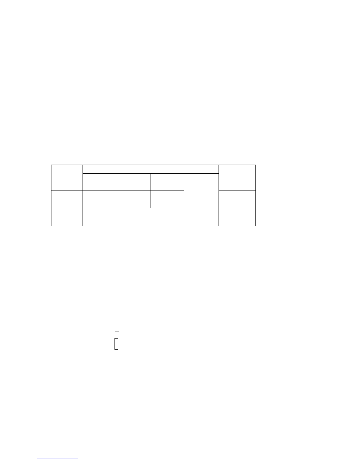
● Tuning range
Band
VHF-Low
VHF-High
Hyper
UHF
S1'-S3', S1
S2-S10,
S11-S20
S21-S41
For TV
For CATV
B/G
Ch2-4
Ch5-12
D/K
Ch1-5
Ch6-12
I/I
Ch4-13
NTSC
Ch2-13
Ch21-69 Ch14-69
In the Lock On state the TV can only be
operated by the Remote Controller.
If any button on the front panel is pressed,
"Child Lock" is displayed on the screen but
the button's function is not performed.
To cancel of this mode, select lock off with
menu button on remote controller only.
(
): SECAM
Front or
Side
Back

- 5 -
DESCRIPTION OF CONTROLS
All the functions can be controlled with the remote control handset.
Some functions can also be adjusted with the buttons on the front
panel of the set.
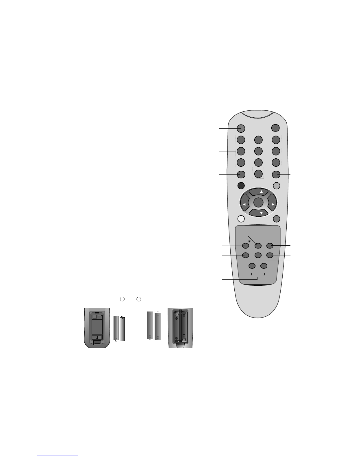
Remote control handset
Before you use the remote control handset, please install the batteries. See the next page.
1. POWER
switches the set on from standby or off to standby.
2. NUMBER BUTTONS
switches the set on from standby or directly select a number.
3. MENU
selects a menu.
4.
DD / EE
(Programme Up/Down)
selects a programme or a menu item.
switches the set on from standby.
FF / GG (Volume Up/Down)
adjusts the volume.
adjusts menu settings.
OK
accepts your selection or displays the current mode.
5. VCR BUTTONS (option)
control a LG video cassette recorder.
6. SSM (Sound Status Memory)
recalls your preferred sound setting.
7. PSM (Picture Status Memory)
recalls your preferred picture setting.
8. EYE/*(option)
switches the eye function on or off.
9. TELETEXT BUTTONS (option)
These buttons are used for teletext.
For further details, see the ‘Teletext’ section.
10. MUTE
switches the sound on or off.
11. ARC (Aspect Ratio Control)
changes the picture format.
12. TV/AV
selects TV or AV mode.
clears the menu / text from the screen.
switches the set on from standby.
13. TURBO PICTURE / SOUND BUTTON
selects Turbo picture / sound.
TEXT/EYE/
Q.VIEW
?
MIX
TIME
REVEAL SLEEP
i
M
(With teletext / Without PIP)
(With teletext / PIP)
TV/AV
SOUND
PICTURE
TURBO
ARC
MUTE
POWER
MENU
PR
VOL
PR
VOL
OK
PLAY
P/STILL
LIST
STOP
REC
REW FF
I/II
TEXT/ PIPEYE/
PR- PR+ SWAP INPUT
SSM
PSM
1 2 3
4 5 6
7 8 9
0
?
MIX
TIME
REVEAL SLEEP
SIZE
STILL
POSITION
9/4PIP
i
M
2
11
1
4
5
7
8
9
12
10
16
14
15
13
17
6
3
9
18
18
- 6 -
0
231
564
897
POWER
MENU
LIST
ARC I/II
SSM
SLEEP
PSM
SOUNDPICTURE
Q.VIEW
PR
OK
VOL VOL
PR
TV/AV
MUTE
TURBO
EYE/
14. LIST
displays the programme table.
15. I/II
selects the language during dual language broadcast (option).
selects the sound output.
16. PIP BUTTONS (option)
PIP
switches the sub picture on or off.
PR +/
-
selects a programme for the sub picture.
SWAP
alternates between main and sub picture.
INPUT
selects the input mode for the sub picture.
SIZE
adjusts the sub picture size.
STILL
freezes motion of the sub picture.
POSITION
relocates the sub picture in clockwise direction.
9/4 PIP
switches on or off the 9 or 4 sub pictures.
17. SLEEP
sets the sleep timer.
18. SWAP or Q.VIEW
returns to the previously viewed programme.
COLOURED BUTTONS
These buttons are used for teletext (only TELETEXT models) or
programme edit.
Battery installation
The remote control handset is powered by two AAA or AA type batteries. To load the batteries, turn the remote control handset over
and open the battery compartment. Install two batteries as indicated by the polarity symbols ( and ) marked inside the compartment.
Note : To avoid damage from possible battery leakage, remove the
batteries if you do not plan to use the remote control handset for an
extended period of time.
+
-
AAA AA
10
(Without teletext / PIP)
1
2
4
3
18
11
8
7
13
12
3
15
14
6
- 7 -
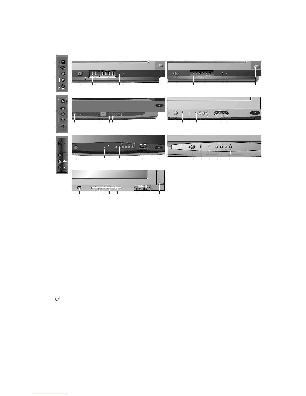
1. MAIN POWER
switches the set on or off.
2. POWER/STANDBY INDICATOR
illuminates brightly when the set is in standby
mode.
dims when the set is switched on.
3. REMOTE CONTROL SENSOR
4. MENU
selects a menu.
5. TV/AV
selects TV or AV mode.
clears the menu from the screen.
switches the set on from standby.
6. OK
accepts your selection or displays the current
mode.
7. (Function)
selects volume, EYE (option), picture items or
brief auto programme while the menus not display.
8.
DD / EE
(Programme Up/Down)
selects a programme or a menu item.
switches the set on from standby.
FF / GG (Volume Down/Up)
adjusts the volume.
adjusts menu settings.
9. +/- (
DD/EE
)
adjusts the function or selects a programme.
switches the set on from standby.
10.AUDIO/VIDEO IN SOCKETS (AV3)
Connect the audio/video out sockets of external equipment to these sockets.
S-VIDEO/AUDIO IN SOCKETS (S-AV) (option)
Connect the video out socket of an S-VIDEO
VCR to the S-VIDEO socket.
Connect the audio out sockets of the S-VIDEO
VCR to the audio sockets as in AV3.
11.HEADPHONE SOCKET (option)
Connect the headphone plug to this socket.
12.EYE (option)
adjusts picture according to the surrounding
conditions.
Note : Do not place any heavy objects (over 4Kg)
on the RT-29FA30/33 series models.
Front panel
MENU
OK
VOL
PR
POWER
MENU O K
VOL
PR
STAND BY
POWER
1
1 2 3 1246 8
4 6 8 2 3 12
POWER
TV/AV
AV3
VIDEO AUDIO
VOL
PR
L/MONO R
S-VIDEO
VIDEO
(L/MONO)
AUDIO
AV3
R
L
Side Panel
S-VIDEO
VIDEO
L/MONO RAUDIO
AV3
11
10
10
11
VIDEO
AUDIO
L
R
MONO
AV3
11
10
CT-29Q26/27 series CT-25Q26/27 series
CT-25/29H46/47 series
CT-25/29H36/37 series
CT-29K36/37 series
POWER
MENU
STAND-BY
OK VOL PR
AV3
VIDEO (L/MONO) AUDIO (R)
POWER
MENU OK VOL PR
1 46 8 2 3 12
1 2 3 5 7 10 11 129
POWER
TV/AV
VOL PR
CT-29M30/32 series
1 2 3 5 7 9
1 2 3 4 6 8 10 12
RT-29FA30/33 series
ON/OFF
MENU OK VOL PR
1 246 8 11 12103
- 8 -
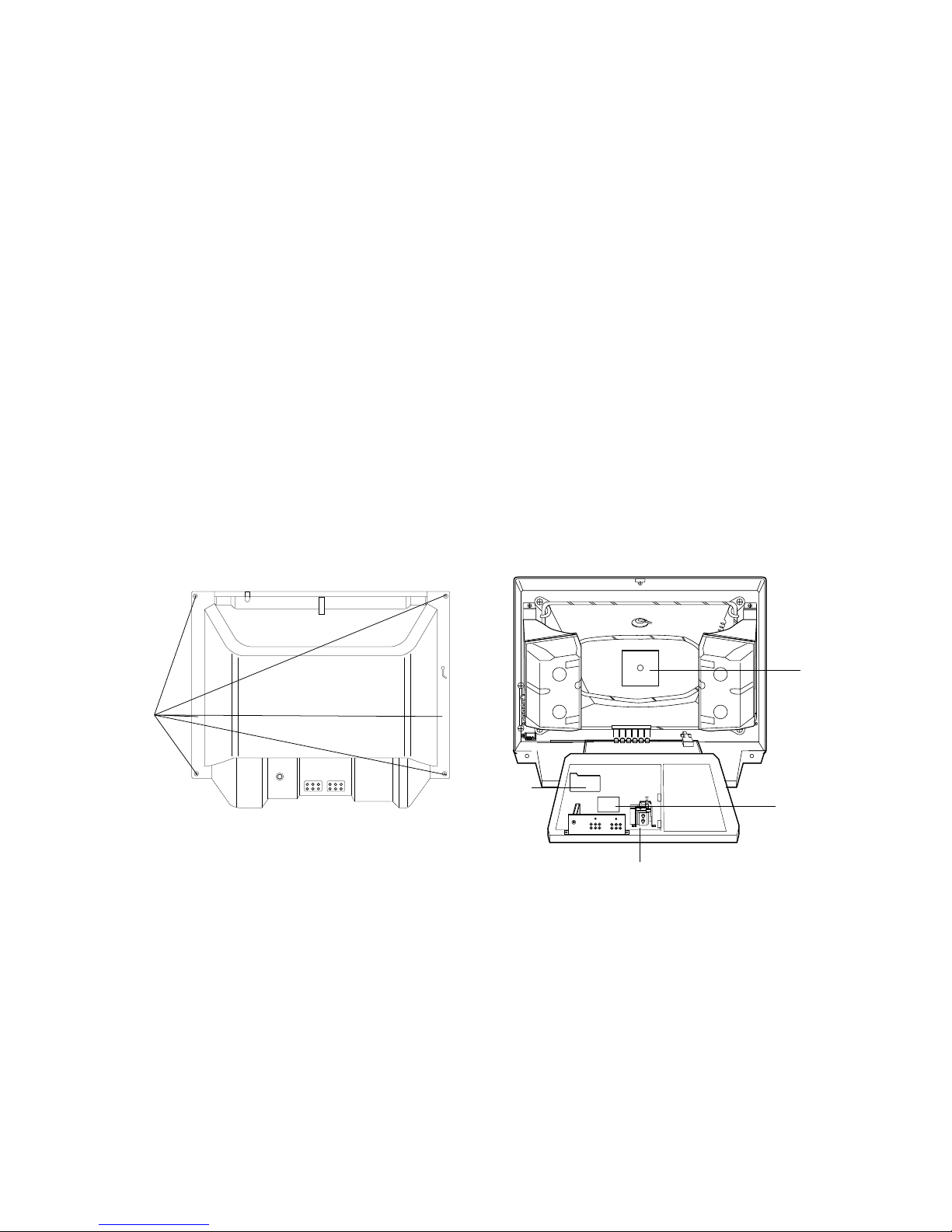
Fig. 2-1
Fig. 2-2
CPT
PCB
Remove
Screws
STEREO
PCB
Main PCB
VCD
PCB
DISASSEMBLY INSTRUCTIONS
Important note
This set is disconnected from the power supply through the
converter transformer. An isolating transformer is necessary
for service operations on the primary side of the converter
transformer.
Back Cabinet Removal
Remove the screws residing on the back cabinet and carefully
separate the back cabinet from the front cabinet. (Fig. 2-1).
Chassis Assy Removal
Grasp both side of Frame and pull it backward smoothly.
CPT Removal
1. Pull out the CPT board from the CPT neck.
2. Place the front cabinet on soft material not to mar the front
surface or damage control knobs.
3. Remove 4 screws securing the picture tube mounting
brackets to the front cabinet.
4. Carefully separate CPT from the front cabinet.
PICTURE TUBE HANDLING CAUTION
Due to high vacuum and large surface area of picture tube, great
care must be exercised when handling picture tube. Always lift
picture tube by grasping it firmly around faceplate.
NEVER LIFT TUBE BY ITS NECK! The picture tube must not be
scratched or subjected to excessive pressure as fracture of
glass may result in an implosion of considerable violence which
can cause personal injury or property damage.
- 9 -
O Safety Precautions
1. It is safe to adjust after using insulating transformer between
the power supply line and chassis input to prevent the risk of
electric shock and protect the instrument.
2. Never disconnect leads while the TV receiver is on.
3. Don't short any portion of circuits while power is on.
4. The adjustment must be done by the correct appliances.
5. Unless otherwise noted, set the line voltage to 230Vac
!10%,
50Hz.
5. The adjustment of TVshould be performed after warming up
for 15 minutes.
O Test Equipment required
1. RF signal generator (with pattern generator)
2. DC Power Supply
3. Multimeter (volt meter)
4. Oscilloscope
5. Color analyzer
O
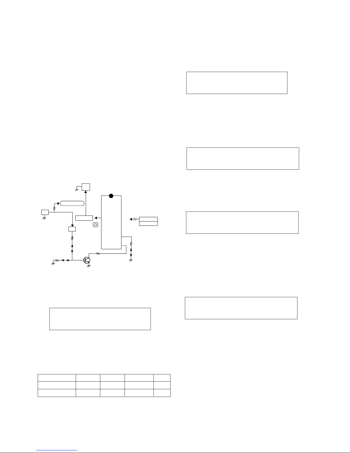
PIF (Picture Intermediate Frequency) Adjustment
1) Connect the measuring equipment to the Main Board as
shown in Fig.1.
2) Set RF frequency and output level of RF SIGNAL
GENERATOR as shown Table 1.
3) Turn off S1 and S3 and on S2.
4) Adjust L104 so that the DC voltage may be 2.4!0.05Vdc.
(Table 1)
O L’ VCO Adjustment (For SECAM-L’ MODEL)
1) Connect the measuring equipment to the Main Board as
shown in Fig.1.
2) Set RF frequency and output level of RF SIGNAL
GENERATOR as shown Table 1.
3) Turn on S1,S3 and off S2.
2) Adjust VR122 so that the DC Voltage may be 2.4!0.05Vdc.
O
RF AGC (Automatic Gain Control) Adjustment
1) Input PAL-B/G 05 CH.
2) Connect Multimeter to TP2(J15),AGC adjustment point.
3) Adjust VR121 until the voltage of Multimeter becomes
2.5!0.1V.
OScreen Voltage Adjustment
1) Tune the RF Modulator to receive a PAL or SECAM signal.
2) Press MIX button on remote controller for Service to get into
the Screen Adjust Mode.
3) Adhere the Color Analyzer on the White window of CPT
face.
4) Adjust Screen Volume of FBT so that the luminance of White
window is 12!1 FL.
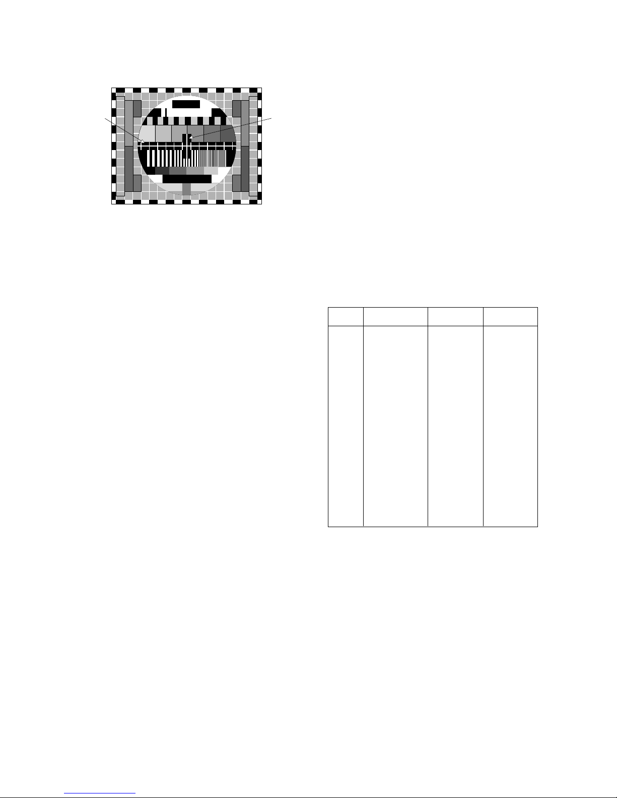
OFocus Adjustment
1) Tune the TV set to receive a digital pattern.
2) Adjust the upper Focus volume of FBT for the best focus of
vertical line B.
3) Adjust the lower Focus volume of FBT for the best focus of
area A.
4) Repeat above step 2) and 3) for the best overall focus.
IC101
TDA4470
TP1(VCO)
IC102(KI7805)
22
7
13
14
1
0.01uF
JP1
L104
9V
PowerSupply
V Multimeter or Oscilloscope
JP2
38.9MHz
34.25MHz
(B/G,D/K,I,L)
(SECAM-L')
100 ohm
S1
5V
4.7 Kohm
S3
S2
JP3
100 ohm
Q122
VR122
R108
R144
Test Point : TP1
Adjust : L104
Test Point : TP1
Adjust : VR122
Frequency
38.9MHz
34.25MHz
System
B/G,D/K/I,SECAM-L
SECAM-L’
Modulation
OFF
OFF
Output level
10mVp-p
10mVp-p
Adjust
L104
VR122
Fig. 1 : Connection Diagram of Equipment for PIF Adjustment
ADJUSTMENT INSTRUCTIONS
Test Point : TP 2(J15)
Adjust : VR121
Test Point : CPT Face
Adjust : Screen Control of FBT
Test Point : Observing Display
Adjust : Focus control of FBT
- 10 -
O Deflection Data Adjustment (Line SVC-2)
NOTE : How to enter into the Line Service Mode with a remocon.
1.Power off.
2.Press the Red button.
3.Press the Green button.
4.Press the Yellow button.
5.Press the Cyan button.
6.Press the OK button.
7.Power On.
1. Preparation for Deflection Adjustment
1) At SVC mode, press the Yellow colored button the SVC
remocon.
And then,deflection data adjustment OSD(SVC2 mode) will
be displayed.
2) Press Channel UP/DOWN button for desirous function
Adjustment.
3) Press Volume UP/DOWN button to adjust the data.
4) Tune the TV set to receive a PAL B/G Digital pattern.
VL (Vertical Linearity)
Adjust so that the boundary line between upper and lower
half is in accord with geometric horizontal center of the CPT.
VA (Vertical Amplitude)
Adjust so that the circle of a digital circle pattern may be
located within the effective screen of the CPT.
SC (Vertical “S” Correction)
Adjust so that all distance between each horizontal lines
are to be the same.
VS (Vertical Shift)
Adjust so that the horizontal center line of a digital circle
pattern is in accord with geometric horizontal center of
the CPT.
HS (Horizontal Shift)
Adjust so that the vertical center line of a digital circle pattern
is in accord with geometric vertical center of the CPT.
EW (Horizontal Width)
Adjust to that a digital circle pattern looks like exact circle.
EP (East-west Parabolar)
Adjust so that middle portion of the outermost left and right
vertical line looks like parallel with vertical lines of the CPT.
EC (East-west Coner)
Adjust so that the vertical line at every 4 corners of the
screen looks like parallel with the vertical lines of the CPT.
ET (East-west Trapezium)
Adjust to make the length of top horizontal line same with
it of the bottom horizontal line.
BOW
In line adjustment, not to change default value is basic.
ANG
In angle adjustment, adjust until inclination of left and right
screen should be precise.
POP (POP Position)
Adjust until the distance between POP and main picture
becomes about 1mm.
(Table 2)
O White Balance Adjustment.(LINE SVC 1)
NOTE : This adjustment should be performed after screen
voltage adjustment.
1) Tune the TV set to receive an 100% white pattern.
2) Press the Yellow button on remote controller in the SVC
Mode.
3) Press PSM (RED) button on remote controller. (Standard
picture)
4) Press PR+ or PR- button for desirous function adjustment.
5) Adjust Low Light status of CR and CB with VOL+ or VOLat CG:50 until X=268!
8,Y=273!8.
6) Adjust High Light status of RG and BGB with VOL+ or
VOL- at CG:370 until X=268!
8,Y=273!8.
7) Repeat above step 5) and 6) until each status of High Light
and Low Light.( for Europe Model: X=288!
8,Y=295!8,
color temperature 9000
o
K).
b
A
B
Fig. 2
Menu
VS
VA
VL
SC
HS
EW
ET
EP
ES
EC
BOW
ANGLE
POP P
0600H~0900H
0050H~00CFH
0025H~00BFH
0000H~009FH
0000H~003FH
0400H~0EFFH
0700H~08FFH
06E0H~0840H
06A0H~0AFFH
0790H~08E0H
FF00H~00FFH
FF00H~00FFH
0790H~08E0H
07BE
0088
00FF
00D9
000D
0A49
0803
078C
0815
0850
0000
0000
0009
Range 29” Flat 29” S-Flat
- 11 -
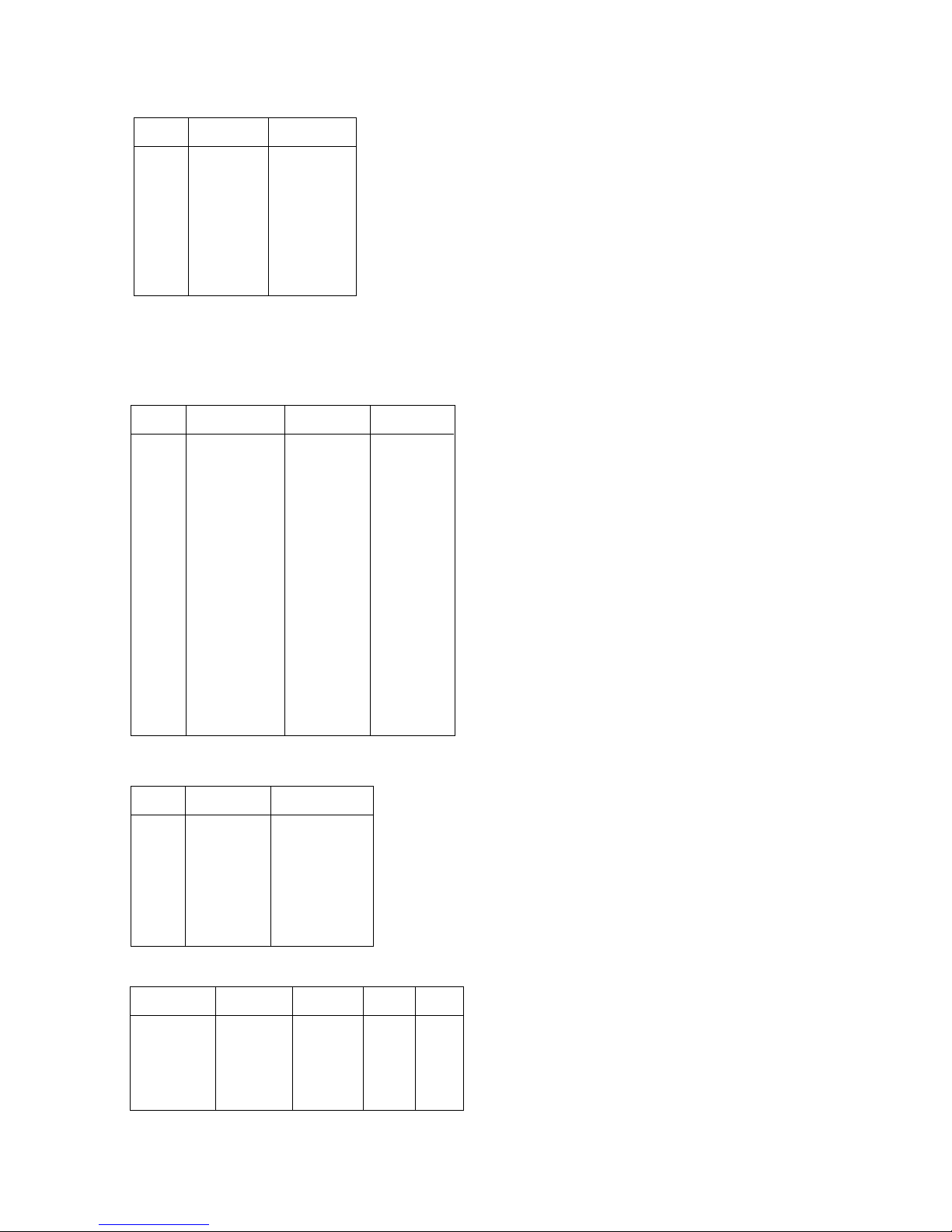
(Table 3)
OSVC Data & PSM,SSM Data.
Table 1. ABL Data (LINE SVC-3)
Table 2. SOUND PRE-SCALER (LINE SVC-4)
Table 3. PSM Data
Menu
DVCO
IBRM
WDRM
BCLTH
BCLTM
BCLGA
SVGA
SVDEL
SVD1
LDLY
HBST
HBSO
0~1FFH
0~3FFH
0~7FFH
0~1FFH
0~1FFH
0~01FF
0~01FF
00C8
0190
0060
000B
000A
0003
0005
0003
FFFE
00F0
0158
Range 29” Flat 29” S-Flat
Menu
FP
NP
SP
S1 VOL
S2 VOL
DVD
0~127
0~127
0~127
0~127
0~127
1
0011
0045
001E
0042
0042
Range DATA
Mode
CONTRAST
BRIGHT
COLOR
SHARPNESS
90
50
50
50
100
55
60
60
60
60
40
30
50
60
40
30
STANDARD DYNAMIC MILD GAME
Menu
CR
CG
CB
RG
GG
BG
0 ~ 511
0 ~ 511
0 ~ 511
0 ~ 511
0 ~ 511
0 ~ 511
80
80
80
370
370
370
Range
DATA
O OPTION Adjustment (LINE-SERVICE OPTION)
Table 4. OPTION Function
- 12 -
OPTION
DVD
GAME
TEXT
TOP
ACMS
CH+AU
EYE
TURBO
SCART
A2 ST
I II SV
MONO
VOL
H-PH
DGS
TILT
200PRO
AV2
HOTEL
KEY
SYS
M-VOL
OSD
T-LAN
1
DVD
GAME
TEXT
TOP
China,Australia
EYE
Turbo Search
SCART
STEREO
I/II
MONO
Middle East Africa,India VOL.
H/Phone
Degaussing
TILT
China Only
Back:JACK(2EA)
HOTEL
0
X
X
X
X
Australia Only
X
X
X
X
X
X
Normal VOL.
X
X
Back:JACK(1EA)
X
Option 1
Option 2
Option 3
Option 4
Menu
 Loading...