

Page 1

LCD TV
SERVICE MANUAL
CAUTION
BEFORE SERVICING THE CHASSIS,
READ THE SAFETY PRECAUTIONS IN THIS MANUAL.
CHASSIS : ML-024B
MODEL : RT/RZ-20LA33
website:http://biz.LGservice.com
e-mail:http://www.LGEservice.com/techsup.html
Nov.,2003
Printed in KoreaP/NO : 3828VD0168L
Page 2

- 2 -
CONTENTS
CONTENTS .............................................................................................. 2
PRODUCT SAFETY ..................................................................................3
DESCRIPTION OF CONTROLS .............................................................. 4
SPECIFICATION........................................................................................7
ADJUSTMENT INSTRUCTION .................................................................9
TROUBLE SHOOTING............................................................................15
BLOCK DIAGRAM...................................................................................16
EXPLODED VIEW .................................................................................. 18
EXPLODED VIEW PARTS LIST..............................................................19
REPLACEMENT PARTS LIST ............................................................... 20
SVC. SHEET ...............................................................................................
Page 3

- 3 -
PRODUCT SAFETY
IMPORTANT SAFETY NOTICE
This manual was prepared for use only by properly trained audiovisual service
technicians. When servicing this product, under no circumstances should the
original design be modified or altered without permission from LG Electronics
Inc. All components should be replaced only with types identical to those in the
original circuit and their physical location, wiring, and lead dress must conform
to original layout upon completion of repairs. If any fuse (or Fusible Resistor) in
this TV receiver is blown, replace it only with the factory specified fuse type and
rating. When replacing a high wattage resistor (Oxide Metal Film Resistor, over
1W), keep the resistor 10mm away from PCB. Always keep wires away from
high voltage or high temperature parts.
Special components are also used to prevent shock and fire hazard.
These components are indicated by the letter “x” included in their component
designators and are required to maintain safe performance. No deviations are
allowed without prior approval by LG Electronis Inc. Service work should be
performed only after you are thoroughly familiar with these safety checks and
servicing guidelines.
Circuit diagrams may occasionally differ from the actual circuit used.
This way, implementation of the latest safety and performance improvement
changes into the set is not delayed until the new service literature is printed.
CAUTION: Do not attempt to modify this product in any way.
Never perform customized installations without manufacturer’s
approval.
Unauthorized modifications will not only void the warranty, but may
lead to property damage or user injury.
GENERAL GUIDANCE
An lsolation Transformer should always be used during the servicing
of a receiver whose chassis is not isolated from the AC power line. Use a
transformer of adequate power rating to protect against personal injury from
electrical shocks. It will also protect the receiver and its components from being
damaged by accidental shorts of the circuitry that may be inadvertently
introduced during the service operation.
Before returning the receiver to the customer, always perform an AC leakage
current check on the exposed metallic parts of the cabinet, such as antennas,
terminals, etc., to be sure the set is safe to operate
without damage of electrical shock.
LEAKAGE CURRENT COLD CHECK
(ANTENNA COLD CHECK)
With the instrument’s AC plug removed from AC source, connect an electrical
jumper across the two AC plug prongs. Place the AC switch in the on position,
connect one lead of ohm-meter to the AC plug prongs tied together, and touch
other ohm-meter lead in turn to each exposed metallic parts such as antenna
terminals, phone jacks, etc. If the exposed metallic part has a return path to the
chassis, the measured resistance should be between 1MΩ and 5.2MΩ. When
the exposed metal has no return path to the chassis the reading must be
infinite. Any other abnormality that exists must be corrected before
the receiver is returned to the customer.
ELECTROSTATICALLY SENSITIVE DEVICES
Some semiconductor (solid-state) devices can be damaged easily by static
electricity. Such components commonly are called Electrostatically Sensitive
(ES) Devices. Examples of typical ES devices are integrated circuits and some
field-effect transistors and semiconductor “chip” components. The following
techniques should be used to help reduce the incidence of component damage
caused by static electricity.
1. Immediately before handling any semiconductor component or
semiconductor-equipped assembly, drain off any electrostatic charge on the
body by touching a known earth ground. Alternatively, obtain and wear a
commercially available discharging wrist strap device, which should be
removed for potential shock reasons prior to applying power to the unit under
test.
2. After removing an electrical assembly equipped with ES devices, place the
assembly on a conductive surface such as an ESD mat, to prevent
electrostatic charge buildup or exposure of the assembly.
3. Use only a grounded-tip soldering iron to solder or unsolder ES devices.
4. Use only an anti-static solder removal device. Some solder removal devices
not classified as “anti-static” can generate electrical charges sufficient to
damage ES devices.
5. Do not use freon-propelled chemicals. These can generate electrical charge
sufficient to damage ES devices.
6. Do not remove a replacement ES device from its protective package until
immediately before you are ready to install it. (Most replacement ES devices
are packaged with leads electrically shorted together by conductive foam,
aluminum foil, or comparable conductive material.)
7. Immediately before removing the protective material from the leads of a
replacement ES device, touch the protective material to the chassis or circuit
assembly into which the device will be installed.
Caution: Be sure no power is applied to the chassis or circuit, and observe
all other safety precautions.
8. Minimize bodily motions when handling unpackaged replacement ES
devices. (Otherwise, seemingly harmless motion, such as the brushing
together of your clothing or the lifting of your foot from a carpeted floor, can
generate static electricity sufficient to damage an ES device.)
Page 4
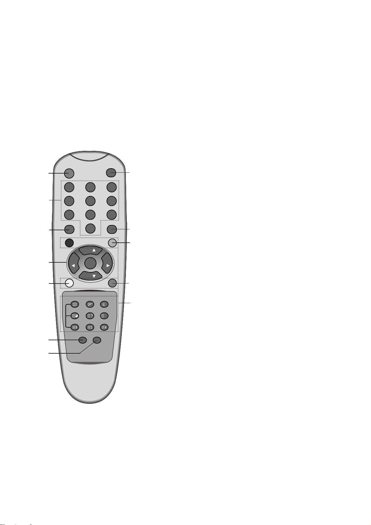
DESCRIPTION OF CONTROLS
- 4 -
0
231
564
897
POWER
MENU TV/AV
SLEEP
LIST
TEXT
MIX
INDEX
TIME REVEAL
SIZE HOLD UPDATE
I/II PSM
Q.VIEW
PR
OK
VOL VOL
PR
MUTE
MODE
M
i
All the functions can be controlled with the remote control handset.
Some functions can also be adjusted with the buttons on the side
panel of the set.
Remote control handset
Before you use the remote control handset, please install the batteries. See the next page.
1. POWER
switches the set on from standby or off to standby.
2. NUMBER BUTTONS
switches the set on from standby or directly select a number.
3. MENU
selects a menu.
4.
D / E
(Programme Up/Down)
selects a programme or a menu item.
switches the set on from standby.
F / G
(Volume Up/Down)
adjusts the volume.
adjusts menu settings.
OK
accepts your selection or displays the current mode.
5. Q.VIEW
returns to the previously viewed programme.
selects a favourite programme.
6. I/II
selects the language during dual language broadcast.
selects the sound output (option).
7. PSM (Picture Status Memory)
recalls your preferred picture setting.
1
2
3
4
5
6
7
8
12
10
11
9
(With TELETEXT)
Page 5
- 5 -
8. MUTE
switches the sound on or off.
9. TV/AV
selects TV or AV monitor mode.
clears the menu from the screen.
switches the set on from standby.
10. SLEEP
sets the sleep timer.
11. LIST
displays the programme table.
12. TELETEXT BUTTONS (option)
These buttons are used for teletext.
For further details, see the ‘Teletext’ section.
COLOURED BUTTONS : These buttons are used for teletext (only
TELETEXT models) or programme edit.
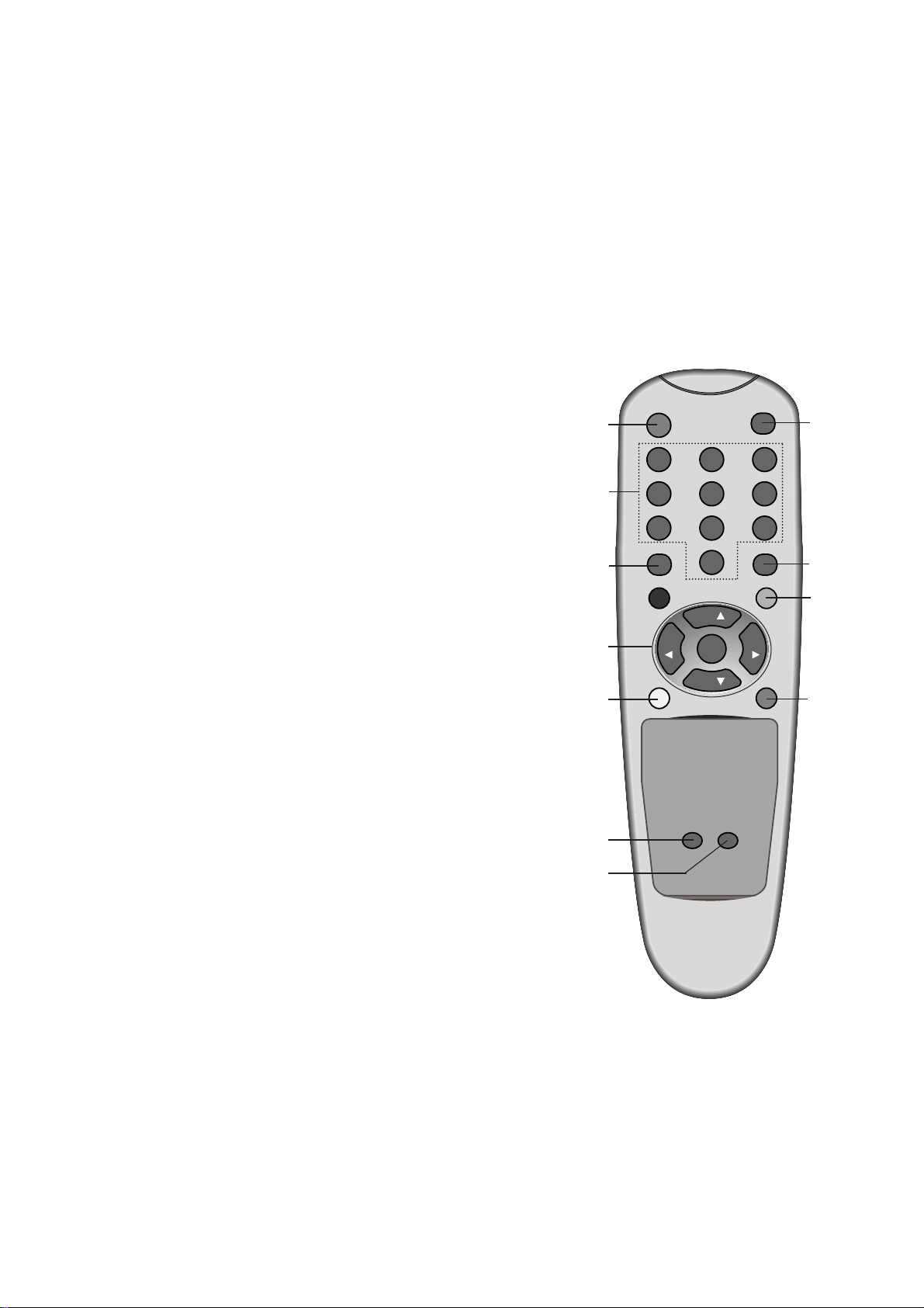
0
2 31
5 64
8 97
POWER
MENU TV/AV
SLEEP
LIST
I/II PSM
Q.VIEW
PR
OK
VOL VOL
PR
MUTE
1
2
3
4
5
6
7
8
10
11
9
(Without TELETEXT)
Page 6

- 6 -
1. POWER (ON/OFF)
switches the set on from standby or off to
standby.
2. TV/AV
selects TV or AV monitor mode.
clears the menu from the screen.
switches the set on from standby.
3. MENU
selects a menu.
4. OK
accepts your selection or displays the current
mode.
5.
FF / GG
(Volume Up/Down)
adjusts the volume.
adjusts menu settings.
6.
DD / EE
(Programme Up/Down)
selects a programme or a menu item.
switches the set on from standby.
7. POWER/STANDBY INDICATOR (rr)
illuminates red in standby mode.
illuminates green when the set is switched on.
8. REMOTE CONTROL SENSOR
9. HEADPHONE SOCKET
Connect the headphone plug to this socket.
10. AUDIO/VIDEO IN SOCKETS (AV)
Connect the audio/video out sockets of external equipment to these sockets.
S-VIDEO/AUDIO IN SOCKETS (SAV)
Connect the video out socket of an S-VIDEO
VCR to the S-VIDEO socket.
Connects the audio out sockets of the SVIDEO VCR to the audio sockets as in AV.
6
Side panel
PR
VOL
OK
MENU
TV/AV
ON/OFF
5
4
3
2
1
7
8
Back panel
S-VIDEO
VIDEO
MONO
AUDIO
L R
H/P
AV
9 10
Page 7
- 7 -
1. Application range
This specification is applied to ML-024B chassis.
2. Requirement for Test
Testing for standard of each part must be followed in below
condition.
(1) Temperature: 25°C ± 5°C(But, CST must be tested 40°C ±
2°C (Humidity: 50%))
(2) Humidity: 65% ± 10%
(3) Power: Standard input voltage (AC 100-220V, 50/60Hz)
(4) Measurement must be performed after heat-run more than
15min.
(5) Adjusting standard for this chassis is followed a special
standard.
3. Test and Inspection method
(1) Capacity: Follow LG electronics TV Testing Standard.
(2) Another Required Standard
Follow the standard of each nation.
SPECIFICATION
NOTE : Specifications and others are subject to change without notice for improvement
.
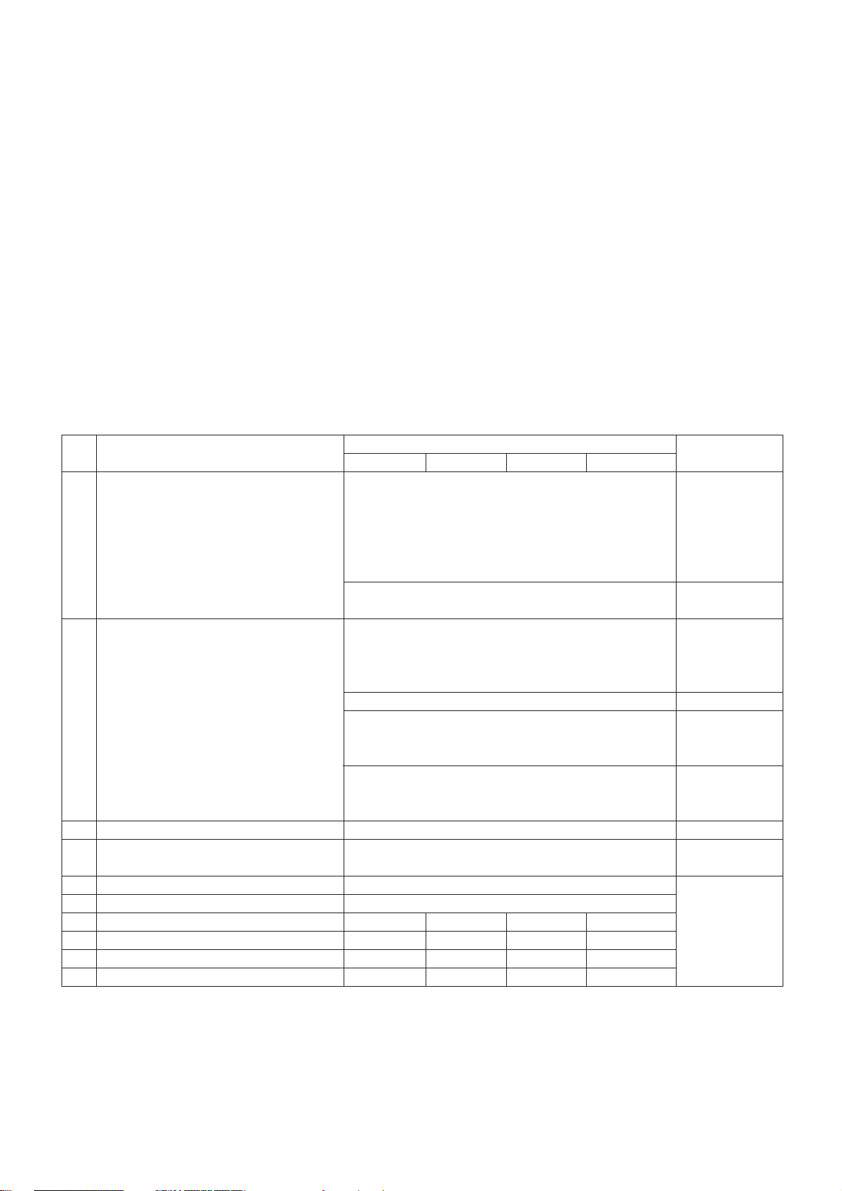
4.General Specification
1
2
3
4
5
6
7
8
9
10
Receivable broadcasting system
RF input channel
Input voltage
Tuning system
Screen size
Aspet ratio
Operating temperature
Operating humidity
Storage temperature
Storage humidity
Specification
Min Typ Max Unit
1)PAL/SECAM-BG
2)PAL/SECAM-DK
3)PAL-I/I
4)SECAM-L/L’
5)NTSC -M
6)NTSC 4.43(AV)
7)PAL N/M
8)NTSC-M
VHF: E02 ~ E12
UHF : E21 ~ E69
CATV : S01 ~ S20
HYPER : S21 ~ S41
L/L’ : B,C,D
VHF : 2 ~13
UHF : 14 ~ 69
CATV : 1 ~ 125
VHF low : 1 ~ M10
VHF high : 4 ~ S22
UHF : S23 ~ 62
AC 100 - 220V ± 10%, 50/60Hz
FVS 100 program
FS
509mm(024B)/330.2(024C)
4:3
0 40 deg
20 80 %
-20 50 deg
30 90 %
Item Remark
No.
EU/Non-EU
(PAL Market)
NTSC Market
PAL
FRANCE
NTSC
JAPAN
PAL, 200PR.(option)
NTSC
Page 8
- 8 -
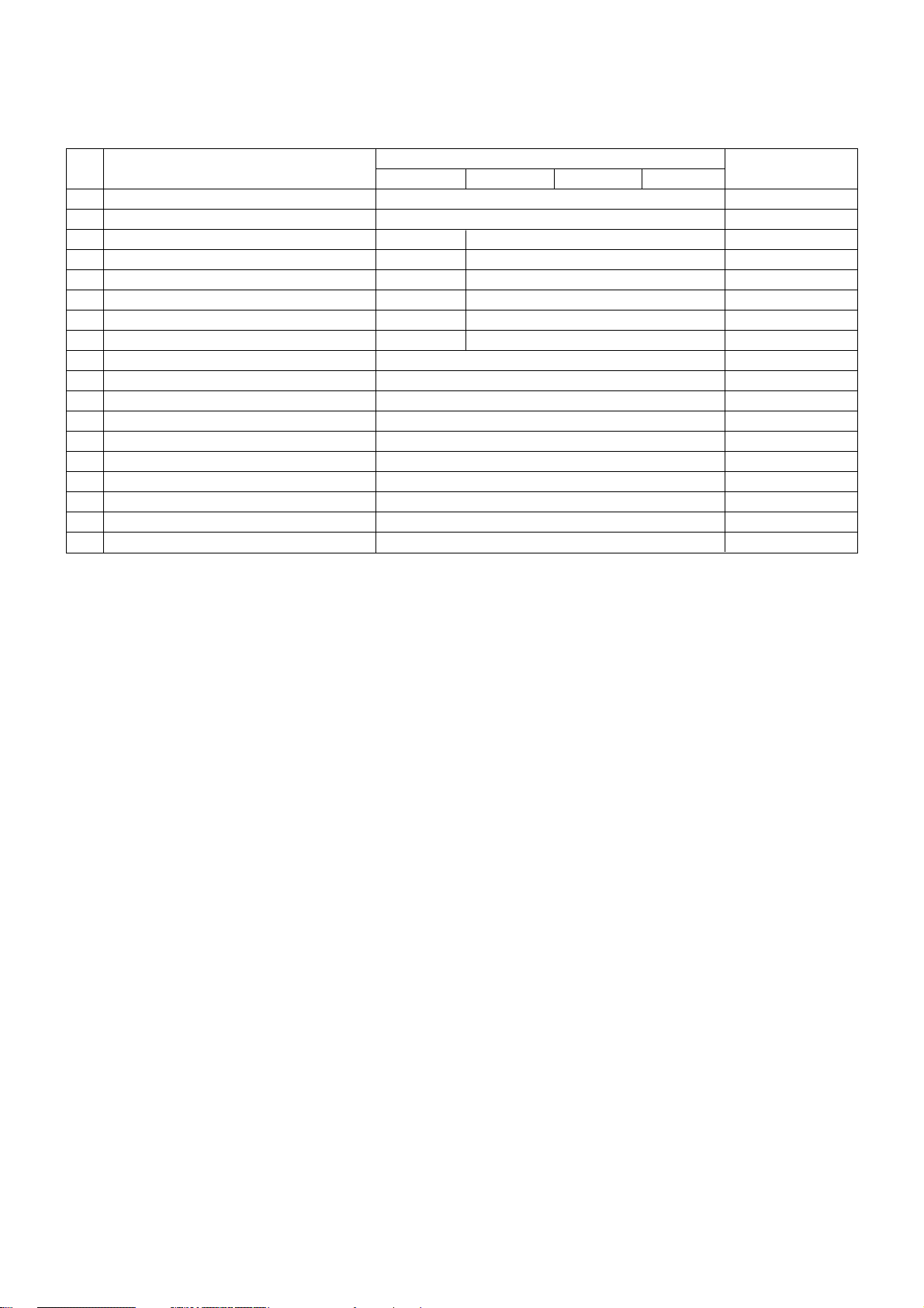
5. Feature and Function
1
2
3
4
5
6
7
8
9
10
11
12
13
14
15
16
17
18
Teletext
REMOCON
Component input( D terminal - For JAPAN)
Scart
AV input
S-viedo input
Video out
H/P output
2 Carrier Stereo
NICAM Stereo
2 Carrier Dual
NICAM Dual
Local Key
Sub Power Key
AVL
On/Off Timer
APC
DASP
Specification
Min Typ Max Unit
TOP,FLOF,LIST 10 page
RC-5 & NEC code (PAL), NEC code(NTSC)
1 Y,P
B,PR
1 Rear (Full Scart)
1 Rear
1 Rear
1 Rear
1 Rear
BG,DK
BG,I,LL’
BG,DK
BG,I,LL’
TV/Video, menu, enter(OK), Vol(F,G), Channel(D,E)
O
O
O
O
O
Item Remark
No.
TOP(option)
Option,Non-EU,NTSC
Option, EU
024B Only
PAL : PSM
PAL : SSM
Page 9

- 9 -
1. Application Object
This instruction is for the application to the LCD TV.
2. Notes
(1) This set uses an adapter, so connect the adapter and the
set correctly before adjustment.
(2) The adjustment must be performed under the correct
sequence.
(3) The adjustment must be performed in the circumstance of
25
!5cC of temperature and 65!10% of relative humidity if
there is no specific designation.
(4) The set must be operated for 15 minutes preliminarily
before adjustment if there is no specific designation.
[ ‘Heat Run’ must be performed with the full white signal or TV
noise signal in the internal part of the set.
[ The time for ‘Heat Run’ can be changed owing to production
plan.
[ Line Test condition (TV): standard color signal 65!1dBuV
3. Y.Pb.Pr LEVEL Adjustment
Only ML-024B
3-1. Required Test Equipment
(1) 802F(QUANTUM DATA: Video Test Generator)
(2) Remote control for adjustment
3-2. Preparation for Adjustment
(1) Adjustment Pattern: R/G/B Color Bar Adjustment Pattern
(Refer to Fig. 1)
3-3. Adjustment
(1) Set with Component mode paragraph exchange.
(2) Setting the signal Format of signal equipment is to be
480P.
(3) Input the Component Jack of the Set with DTV output
(Y.Pb.Pr) of adjustment equipment.
(4) With lower part Fig. 1 the same Pattern does to come out
in the Set.
(5) Enter the adjustment mode using IN-START Key of Adjust
Remocon.
(6) Enter the Component adjustment mode with Fig. 1.
(7) From R Color Bar adjustment Pattern value of the DVDRO
using Vol Key of Adjust Remocon adjust disappear A
Pattern of Fig. 1. (When reduces the Data value, Pattern of
the A comes to dawn)
(8) When the adjustment of the DVDRO is completed, input
adjustment Pattern in G --> B order and adjust DVDGO -->
DVDBO and adjust the Pattern of the A not to be visible.
(9) When the adjustment is completed in DVDRO --> DVDGO
--> DVDBO order, adjust adjustment data of the DVDRO to
be -3 Step and memory adjustment data using ENTER of
Adjust Remocon.
(10) After adjustment is completed, exit the adjustment mode
using EXIT Key of Adjust Remocon.
ADJUSTMENT INSTRUCTION
(Fig. 1)
Page 10

- 10 -
OPTION
Data
200PR
TEXT
I/II SV
TOP
A2 ST SYS
0
1
2
3
4
5
6
7
8
9
10
11
12
13
14
15
16
17
18
19
20
21
22
23
24
25
26
27
28
29
30
31
32
33
34
35
36
37
38
39
40
41
42
0
0
0
0
0
0
0
0
0
0
0
0
0
0
0
0
0
0
0
0
0
0
0
0
0
0
0
0
0
0
0
0
0
0
0
0
0
0
0
0
0
0
0
0
0
0
0
0
0
0
0
0
0
0
0
0
0
0
0
0
0
0
0
0
0
0
0
0
0
0
0
0
0
0
0
0
0
0
0
0
0
0
0
0
0
0
0
0
0
0
0
0
0
0
0
0
0
0
0
0
0
0
0
0
0
0
0
0
0
0
0
0
0
0
0
0
0
0
1
1
1
1
1
1
1
1
1
1
1
0
0
0
0
0
0
0
0
0
0
0
0
0
0
0
0
1
1
1
1
1
1
1
1
1
1
1
1
1
1
1
1
0
0
0
0
0
0
0
0
0
0
0
0
0
0
0
1
1
1
1
0
0
0
0
1
1
1
1
0
0
0
0
1
1
1
1
0
0
0
0
1
1
1
1
0
0
0
0
1
1
1
1
0
0
0
0
1
2
3
0
1
2
3
0
1
2
3
0
1
2
3
0
1
2
3
0
1
2
3
0
1
2
3
0
1
2
3
0
1
2
3
0
1
2
3
0
1
2
SCART
0
0
0
0
0
0
0
0
1
1
1
1
1
1
1
1
0
0
0
0
0
0
0
0
1
1
1
1
1
1
1
1
0
0
0
0
0
0
0
0
1
1
1
OPTION
Data
200PR
TEXT
I/II SV
TOP
A2 ST SYS
43
44
45
46
47
48
49
50
51
52
53
54
55
56
57
58
59
60
61
62
63
64
65
66
67
68
69
70
71
72
73
74
75
76
77
78
79
80
81
82
83
84
85
0
0
0
0
0
0
0
0
0
0
0
0
0
0
0
0
0
0
0
0
0
0
0
0
0
0
0
0
0
0
0
0
0
0
0
0
0
0
0
0
0
0
0
0
0
0
0
0
0
0
0
0
0
0
0
0
0
0
0
0
0
0
0
0
1
1
1
1
1
1
1
1
1
1
1
1
1
1
1
1
1
1
1
1
1
1
1
1
1
1
1
1
1
1
1
1
1
1
1
1
1
1
1
1
1
1
1
0
0
0
0
0
0
0
0
0
0
0
0
0
0
0
0
0
0
0
0
0
0
0
0
0
0
0
1
1
1
1
1
1
1
1
1
1
1
1
1
1
1
1
0
0
0
0
0
0
0
0
0
0
0
0
0
0
0
0
1
1
1
1
1
1
0
1
1
1
1
0
0
0
0
1
1
1
1
0
0
0
0
1
1
1
1
0
0
0
0
1
1
1
1
0
0
0
0
1
1
1
1
0
0
0
0
1
1
3
0
1
2
3
0
1
2
3
0
1
2
3
0
1
2
3
0
1
2
3
0
1
2
3
0
1
2
3
0
1
2
3
0
1
2
3
0
1
2
3
0
1
SCART
1
1
1
1
1
0
0
0
0
0
0
0
0
1
1
1
1
1
1
1
1
0
0
0
0
0
0
0
0
1
1
1
1
1
1
1
1
0
0
0
0
0
0
4. Option 1 data setting (200PR ~ A2 ST:1bit, SYS:2bit composition)
Page 11

- 11 -
OPTION
Data
200PR
TEXT
I/II SV
TOP
A2 ST SYS
86
87
88
89
90
91
92
93
94
95
96
97
98
99
100
101
102
103
104
105
106
107
108
109
110
111
112
113
114
115
116
117
118
119
120
121
122
123
124
125
126
127
128
129
130
131
0
0
0
0
0
0
0
0
0
0
0
0
0
0
0
0
0
0
0
0
0
0
0
0
0
0
0
0
0
0
0
0
0
0
0
0
0
0
0
0
0
0
1
1
1
1
1
1
1
1
1
1
1
1
1
1
1
1
1
1
1
1
1
1
1
1
1
1
1
1
1
1
1
1
1
1
1
1
1
1
1
1
1
1
1
1
1
1
0
0
0
0
0
0
0
0
0
0
0
0
0
0
1
1
1
1
1
1
1
1
1
1
1
1
1
1
1
1
1
1
1
1
1
1
1
1
1
1
1
1
1
1
1
1
0
0
0
0
1
1
1
1
1
1
1
1
1
1
0
0
0
0
0
0
0
0
0
0
0
0
0
0
0
0
1
1
1
1
1
1
1
1
1
1
1
1
1
1
1
1
0
0
0
0
1
1
0
0
0
0
1
1
1
1
0
0
0
0
1
1
1
1
0
0
0
0
1
1
1
1
0
0
0
0
1
1
1
1
0
0
0
0
1
1
1
1
0
0
0
0
2
3
0
1
2
3
0
1
2
3
0
1
2
3
0
1
2
3
0
1
2
3
0
1
2
3
0
1
2
3
0
1
2
3
0
1
2
3
0
1
2
3
0
1
2
3
SCART
0
0
1
1
1
1
1
1
1
1
0
0
0
0
0
0
0
0
1
1
1
1
1
1
1
1
0
0
0
0
0
0
0
0
1
1
1
1
1
1
1
1
0
0
0
0
OPTION
Data
200PR
TEXT
I/II SV
TOP
A2 ST SYS
132
133
134
135
136
137
138
139
140
141
142
143
144
145
146
147
148
149
150
151
152
153
154
155
156
157
158
159
160
161
162
163
164
165
166
167
168
169
170
171
172
173
174
175
176
177
1
1
1
1
1
1
1
1
1
1
1
1
1
1
1
1
1
1
1
1
1
1
1
1
1
1
1
1
1
1
1
1
1
1
1
1
1
1
1
1
1
1
1
1
1
1
0
0
0
0
0
0
0
0
0
0
0
0
0
0
0
0
0
0
0
0
0
0
0
0
0
0
0
0
0
0
0
0
0
0
0
0
0
0
0
0
0
0
0
0
0
0
0
0
0
0
0
0
0
0
0
0
0
0
0
0
0
0
0
0
0
0
0
0
0
0
0
0
0
0
1
1
1
1
1
1
1
1
1
1
1
1
1
1
1
1
1
1
0
0
0
0
0
0
0
0
0
0
0
0
1
1
1
1
1
1
1
1
1
1
1
1
1
1
1
1
0
0
0
0
0
0
0
0
0
0
0
0
0
0
0
0
1
1
1
1
1
1
0
0
0
0
1
1
1
1
0
0
0
0
1
1
1
1
0
0
0
0
1
1
1
1
0
0
0
0
1
1
1
1
0
0
0
0
1
1
1
1
0
0
0
1
2
3
0
1
2
3
0
1
2
3
0
1
2
3
0
1
2
3
0
1
2
3
0
1
2
3
0
1
2
3
0
1
2
3
0
1
2
3
0
1
2
3
0
1
SCART
0
0
0
0
1
1
1
1
1
1
1
1
0
0
0
0
0
0
0
0
1
1
1
1
1
1
1
1
0
0
0
0
0
0
0
0
1
1
1
1
1
1
1
1
0
0
Page 12

- 12 -
OPTION
Data
200PR
TEXT
I/II SV
TOP
A2 ST SYS
178
179
180
181
182
183
184
185
186
187
188
189
190
191
192
193
194
195
196
197
198
199
200
201
202
203
204
205
206
207
208
209
210
211
212
213
214
215
216
217
218
219
220
221
222
223
1
1
1
1
1
1
1
1
1
1
1
1
1
1
1
1
1
1
1
1
1
1
1
1
01
1
1
1
1
1
1
1
1
1
1
1
1
1
1
1
1
1
1
1
1
1
0
0
0
0
0
0
0
0
0
0
0
0
0
0
1
1
1
1
1
1
1
1
1
1
1
1
1
1
1
1
1
1
1
1
1
1
1
1
1
1
1
1
1
1
1
1
1
1
1
1
1
1
1
1
1
1
1
1
1
1
0
0
0
0
0
0
0
0
0
0
0
0
0
0
0
0
0
0
0
0
0
0
0
0
0
0
0
0
0
0
0
0
1
1
1
1
1
1
1
1
1
1
1
1
1
1
0
0
0
0
0
0
0
0
0
0
0
0
0
0
0
0
1
1
1
1
1
1
1
1
1
1
1
1
1
1
1
1
0
0
1
1
1
1
0
0
0
0
1
1
1
1
0
0
0
0
1
1
1
1
0
0
0
0
1
1
1
1
0
0
0
0
1
1
1
1
0
0
0
0
1
1
1
1
2
3
0
1
2
3
0
1
2
3
0
1
2
3
0
1
2
3
0
1
2
3
0
1
2
3
0
1
2
3
0
1
2
3
0
1
2
3
0
1
2
3
0
1
2
3
SCART
0
0
0
0
0
0
1
1
1
1
1
1
1
1
0
0
0
0
0
0
0
0
1
1
1
1
1
1
1
1
0
0
0
0
0
0
0
0
1
1
1
1
1
1
1
1
OPTION
Data
200PR
TEXT
I/II SV
TOP
A2 ST SYS
224
225
226
227
228
229
230
231
232
233
234
235
236
237
238
239
240
241
242
243
244
245
246
247
248
249
250
251
252
253
254
255
1
1
1
1
1
1
1
1
1
1
1
1
1
1
1
1
1
1
1
1
1
1
1
1
1
1
1
1
1
1
1
1
1
1
1
1
1
1
1
1
1
1
1
1
1
1
1
1
1
1
1
1
1
1
1
1
1
1
1
1
1
1
1
1
1
1
1
1
1
1
1
1
1
1
1
1
1
1
1
1
1
1
1
1
1
1
1
1
1
1
1
1
1
1
1
1
0
0
0
0
0
0
0
0
0
0
0
0
0
0
0
0
1
1
1
1
1
1
1
1
1
1
1
1
1
1
1
1
0
0
0
0
1
1
1
1
0
0
0
0
1
1
1
1
0
0
0
0
1
1
1
1
0
0
0
0
1
1
1
1
0
1
2
3
0
1
2
3
0
1
2
3
0
1
2
3
0
1
2
3
0
1
2
3
0
1
2
3
0
1
2
3
SCART
0
0
0
0
0
0
0
0
1
1
1
1
1
1
1
1
0
0
0
0
0
0
0
0
1
1
1
1
1
1
1
1
Page 13

- 13 -
5. Option2 data(ACMS~BBACK:1bit,LANG:3bit)
OPTION
Data
ACMS
VOL
BBACK LANG
0
1
2
3
4
5
6
7
8
9
10
11
12
13
14
15
16
17
18
19
20
21
22
23
24
25
26
27
28
29
30
31
0
0
0
0
0
0
0
0
0
0
0
0
0
0
0
0
0
0
0
0
0
0
0
0
0
0
0
0
0
0
0
0
0
0
0
0
0
0
0
0
0
0
0
0
0
0
0
0
1
1
1
1
1
1
1
1
1
1
1
1
1
1
1
1
0
0
0
0
0
0
0
0
1
1
1
1
1
1
1
1
0
0
0
0
0
0
0
0
1
1
1
1
1
1
1
1
0
1
2
3
4
5
6
7
0
1
2
3
4
5
6
7
0
1
2
3
4
5
6
7
0
1
2
3
4
5
6
7
32
33
34
35
36
37
38
39
40
41
42
43
44
45
46
47
48
49
50
51
52
53
54
55
56
57
58
59
60
61
62
63
OPTION
Data
ACMS
VOL
BBACK LANG
1
1
1
1
1
1
1
1
1
1
1
1
1
1
1
1
1
1
1
1
1
1
1
1
1
1
1
1
1
1
1
1
0
0
0
0
0
0
0
0
0
0
0
0
0
0
0
0
1
1
1
1
1
1
1
1
1
1
1
1
1
1
1
1
0
0
0
0
0
0
0
0
1
1
1
1
1
1
1
1
0
0
0
0
0
0
0
0
1
1
1
1
1
1
1
1
0
1
2
3
4
5
6
7
0
1
2
3
4
5
6
7
0
1
2
3
4
5
6
7
0
1
2
3
4
5
6
7
Page 14

- 14 -
6. Option3 data(IIC AFT~CH+AU:1bit)
OPTION
Data
HiDEV
TSS
IIC T MONO CH+AUS
0
1
2
3
4
5
6
7
8
9
10
11
12
13
14
15
16
17
18
19
20
21
22
23
24
25
26
27
28
29
30
31
0
0
0
0
0
0
0
0
0
0
0
0
0
0
0
0
1
1
1
1
1
1
1
1
1
1
1
1
1
1
1
1
0
0
0
0
0
0
0
0
1
1
1
1
1
1
1
1
0
0
0
0
0
0
0
0
1
1
1
1
1
1
1
1
0
0
0
0
1
1
1
1
0
0
0
0
1
1
1
1
0
0
0
0
1
1
1
1
0
0
0
0
1
1
1
1
0
0
1
1
0
0
1
1
0
0
1
1
0
0
1
1
0
0
1
1
0
0
1
1
0
0
1
1
0
0
1
1
0
1
0
1
0
1
0
1
0
1
0
1
0
1
0
1
0
1
0
1
0
1
0
1
0
1
0
1
0
1
0
1
Page 15

- 15 -
1 No sound Defective Reset IC of IC604. 1) Check volume and speaker.
- Speaker Defective MSP3410G of IC601. - Sound comes out only when being inputted into Audio
- Earphone Defective B+(8V) of IC604. L/R.
2) Check after replacing IC603.
3) Replace IC601.
4) Check and replace B+ of IC604.
2 Video color beat noise Earphone shield case being touched.
Check the mould of shield and SJ209, Replace shield case.
Soldering IC501. 1) Check signal of Video input.
2) Check signal of R.G.B output.
3) Re-soldering
1 No screen Input error of inverter connector 1) Bend the pin legs of
P802B
connector -> recheck them
2) Check and repair IC805 SI4925.
P1 and Pin 50 connector 1) Check and fix P1 connector
being slipped out
Cracked components and 1)Check and repair tuner board and main board
soldering at tuner board 2)Solder Q403
2 Dark screen 1) Defective LCD lamp 1) Replace the inverter
2) Defective inverter 2) Replace the LCD lamp
3) Input error of inverter connector 3) Check the connector input.
TROUBLE SHOOTING
1. General Features
No. Symptom Cause Check Point
Check Point
2. TV and external input
No. Symptom Cause
Page 16

BLOCK DIAGRAM
- 16 -
ML-024B CHASSIS BLOCK DIAGRAM
POWER
(SMPS)
INVEERTER
Assay
TUNER
TUNER
ANT (RF) Input
DVD/DTV Input
(480I/480P)
R/G/B/FB L/R in
TV L/R out
CVBS in ID-1
IC501
SCALER(Format Converter)
LG8801
IC701
AD Converter
AD9883
RF V.
AFT
SIF
AUDIO
SW2
SW1B+IF-0UT
ADC
33V
SDA
SCL
CTR
AGC
SCL/SDASCL/SDA
MSP-34XX
SIF : 2, SCART : 4
MONO : 1
I2S : 2
------18.432MHz---
L-SPK / WOOFER
H/P, I2S
SCART OUT : 2
IC602
LA4282
8.0V8.0V
15V15V
5.0V5.0V
RESET 4.2V
EEP
ROM
EEP
ROM
IC100
MICOM / TXT
6.0MHz
SCL1/SDA1
IC502
OSD
DC In
33V
15V
S-T 5V/5V
S-T 5V/3.3V
INV-On/Off
(FROM MICOM)
3.3V3.3V
R/Y(8) G/U(8) B/V(8)
Y/U/V
R(8) G(8) B(8)R(8) G(8) B(8)
RF V.
YUV
A/V V.
S-Y/C
SCART V.
ST-BY
3.3V/2.5V
5.0V5.0V
R/G/B/FB
SCL/SDA
CVBS(From IC352)
POWER
DC-DC Converter
IC601
MULTISTANDARD
SOUND PROCESSOR
SCL/SDA
SIF
A/V L,R
DVD L/R
S. L/R
S. L/R H/P L,R
H/V Sync
Enable,CLK
TO MODULE(50P)
TO MODULE(50P)
5V5V
15V
6-LAMP OUT
(7mA/EA)
SCART R/G/B/FB
SCART V.
CAP./TXT
(R/G/B/FB)
15V(DC)
RF V.
S. L/R(In/Out)
..
. .
H/P S-Input VIDEO Input VIDEO Output
..
. .
H/P S-Input VIDEO Input VIDEO Output
H/P L,R
A/V V.S-V.
A/V L,R
AUDIO MONO
INVERTER
MSP34**
TUNER
MICOM, TUNER
LG8801, MODULE,
AD9883,MICOM
NTSC/PAL/SECAM Decoder with Analog
YPbPr/RGB Input and Digital YCbCr/Digital
RGB Input
===============================
IC352
Video
S/W
CXA2040
Video
3W
3W
V. OUT
A/V L,R OUT
CVBS(To Micom )
CVBS(To MJ201)
MJ201
DVD(Audio)
H/V
DVD L/R
Page 17

MEMO
- 17 -
Page 18

- 18 -
EXPLODED VIEW
500
112
420
410
120
560
330
300
340
530
310
112
400
430
500
540
Page 19

- 19 -
112 6306V20002A LCD MODULE,V201V1-T01 VGA CHIMEI TFT COLOR
120 120-D44E SPEAKER,FULLRANGE G705/080701A MOTORJOY 4OHM 3/5W 80DB 70X50MM
300 3091V00A20W CABINET ASSEMBLY RT/RZ-20LA33(SET) NON ML024B .
310 5020V00552G BUTTON,CONTROL PR-20LA30 HF-380 7 KEY METALIC BLUE
330 5020V00553D BUTTON,POWER RP-15LA31 NON 1 KEY SET
340 3091V00A19K CABINET ASSEMBLY,RZ-20LA31 STEREO ML024B .
400 3809V00373G BACK COVER ASSEMBLY,RT-20LA33(407AF) SET NON (CASA)
3809V00373L BACK COVER ASSEMBLY,RT-20LA33(SET,HB) NON HF-380 (LGEGF,ALPHA)
3809V00373M BACK COVER ASSEMBLY,RT-20LA33(SET,LGEMT)NON HF-380
3809V00373P BACK COVER ASSEMBLY,RT-20LA33.AHCLKG NON .(LGEAP)
3809V00373S BACK COVER ASSEMBLY,RZ-20LA33 1SCART 3850VC0002F(LGEAK)
410 4811V00082B BRACKET ASSEMBLY,STAND RT/RZ-20LA33(SET) ML024B .
420 4950V00081B METAL,SUPPORTER SUS HINGE FIXER
430 3550V00202F COVER,REAR AV 20LA33/31 ABS, HF-380 .
450 4950V00159A METAL,MAIN FRAME EGI AU LCD
4950V00159C METAL, FRAME EGI 4850V00013Z/109A(LGEAK)
500 4950V00160A METAL,SHIELD EGI 20LA30
510 6871VSMA74A PWB(PCB) ASSEMBLY,SUB MF-002A CTL ASSY RE/RL/RN-20LA30
520 6871VMMQ95A PWB(PCB) ASSEMBLY,MAIN ML-024B PCB ASSY MAIN
6871VMMR37A PWB(PCB) ASSEMBLY,MAIN ML-024B RZ-20LA33 PCB ASSY MAIN(LGEAK)
530 6871VSMV36A PWB(PCB) ASSEMBLY,SUB POWER ML024B 20INCH POWER ASSY
540 6633VA0003S INVERTER ASSEMBLY 15V NON ECT FRONTEC FIF2066-32A 6633VA0003J
EXPLODED VIEW PARTS LIST
No.
PART NO.
DESCRIPTION
Page 20

REPLACEMENT PARTS LIST
LOCA. NO PART NO DESCRIPTION
D601
D602
D802
ZD202
ZD203
ZD204
ZD220
ZD221
ZD222
ZD400
C10
C101
C113
C209
C219
C220
C211
C212
C225
C226
C254
C255
C278
C281
C282
C289
C351
C353
C354
C356
C357
C362
C364
C380
C381
C383
C403
C404
C408
C412
C499
C501
C523
C526
C541
0DD181009AB
0DD181009AB
0DD100009AM
0DZRM00178A
0DZRM00178A
0DZRM00178A
0DZRM00178A
0DZRM00178A
0DZRM00178A
0DZ330009BA
0CE337ZF638
0CE107BF618
0CE107BF618
0CE476DF618
0CE226DF618
0CE226DF618
0CE106DF618
0CE227DD618
0CE106DF618
0CE106DF618
0CE105BK618
0CE105BK618
0CE225DK618
0CE105BK618
0CE105BK618
0CE104DK618
0CE227DF618
0CE475DK618
0CE106DF618
0CE106DF618
0CE106DF618
0CE107DF618
0CE336DF618
0CE105BK618
0CE106DF618
0CE106DF618
0CE476DH618
0CE108DD618
0CE106DK618
0CE105DK618
0CE476DF618
0CE107DF618
0CE104DK618
0CE107DF618
0CE107DF618
DIODE, KDS181 TP KEC - 85V - - - 300MA
DIODE, KDS181 TP KEC - 85V - - - 300MA
DIODE, EU1ZV(1) TP SANKEN
DIODE,R/TP SMD 0.2W 5.1V 5MA -PF
DIODE,R/TP SMD 0.2W 5.1V 5MA -PF
DIODE,R/TP SMD 0.2W 5.1V 5MA -PF
DIODE,R/TP SMD 0.2W 5.1V 5MA -PF
DIODE,R/TP SMD 0.2W 5.1V 5MA -PF
DIODE,R/TP SMD 0.2W 5.1V 5MA -PF
DIODE, ZENER HZT33 TAPING
330UF SEP 16V 20% FM5 TP 5
100UF KME 16V M FL TP5
100UF KME 16V M FL TP5
47UF STD 16V M FL TP5
22UF STD 16V M FL TP5
22UF STD 16V M FL TP5
10UF STD 16V M FL TP5
220UF STD 10V M FL TP5
10UF STD 16V M FL TP5
10UF STD 16V M FL TP5
1UF KME 50V M FL TP5
1UF KME 50V M FL TP5
2.2UF STD 50V 20% FL TP 5
1UF KME 50V M FL TP5
1UF KME 50V M FL TP5
0.1000UF STD 50V M FL TP5
220UF STD 16V M FL TP5
4.7UF STD 50V 20% FL TP 5
10UF STD 16V M FL TP5
10UF STD 16V M FL TP5
10UF STD 16V M FL TP5
100UF STD 16V M FL TP5
33UF STD 16V M FL TP5
1UF KME 50V M FL TP5
10UF STD 16V M FL TP5
10UF STD 16V M FL TP5
47UF STD 25V 20% FL TP 5
1000UF STD 10V M FL TP5
10UF STD 50V M FL TP5
1UF STD 50V M FL TP5
47UF STD 16V M FL TP5
100UF STD 16V M FL TP5
0.1000UF STD 50V M FL TP5
100UF STD 16V M FL TP5
100UF STD 16V M FL TP5
LOCA. NO PART NO DESCRIPTION
IC101
IC102
IC351
IC352
IC601
IC602
IC603
IC604
IC801
IC905
Q101
Q102
IC2
IC802
IC803
IC804
IC805
Q1
Q100
Q1101
Q1102
Q1103
Q200
Q201
Q202
Q353
Q354
Q402
Q403
Q404
Q405
Q406
Q407
Q502
Q510
Q551
Q560
Q602
Q603
Q604
Q605
Q651
Q801
Q802
Q803
0IAL241610B
0IFA752700A
0IMCRFA010A
0ISO204000A
0IMCRMN011D
0ISA428200A
0IKE704200J
0IMCRFA009A
0ITC786000A
0ISA428200A
0IFA270000A
0IFA270000A
0TF492509AA
0TFVI80001A
0TFVI80001A
0TFVI80005A
0TF492509AA
0TR387500AA
0TR387500AA
0TR387500AA
0TR387500AA
0TR387500AA
0TR387500AA
0TR387500AA
0TR387500AA
0TR150400BA
0TR150400BA
0TR150400BA
0TR150400BA
0TR387500AA
0TR387500AA
0TR387500AA
0TR387500AA
0TR150400BA
0TR150400BA
0TR150400BA
0TR387500AA
0TR150400BA
0TR150400BA
0TR150400BA
0TR150400BA
0TR150400BA
0TR387500AA
0TR150400BA
0TR387500AA
IC, AT24C16A-10PI-2.7 8PIN DIP ST
IC, KA75270Z 3 TP RE-SET IC MC-007
IC, KA7809R, FAIRCHILD 2P D-PAK, R/TP
IC, CXA2040AQ 32P,QFP BK IIC BUS
IC, MSP3410G QA B8 V3 80P QFP TRAY
IC, LA4282 12S 2CHX10W AUDIO AMP
IC, KIA7042AF SOT-89 TP 4.2V VOLTAGE
IC, KA78M08RTM, 2P D-PAK, R/TP
IC, SI786 28SSOP TP DUAL-OUTPUT
IC, LA4282 12S 2CHX10W AUDIO AMP
IC, 2N7000TA TO-92, 3P TP 60V/0.2A
IC, 2N7000TA TO-92, 3P TP 60V/0.2A
TR, SI4925DY TP TEMIC 30V 6.1A SO-8
TR, VISHAY SI4808DY R/TP SO-8 30V 7.5A
TR, VISHAY SI4808DY R/TP SO-8 30V 7.5A
TR, VISHAY SI4963DY R/TP SO-8 -20V 6.2A
TR, SI4925DY TP TEMIC 30V 6.1A SO-8
TR, CHIP 2SC3875S(ALY) KEC
TR, CHIP 2SC3875S(ALY) KEC
TR, CHIP 2SC3875S(ALY) KEC
TR, CHIP 2SC3875S(ALY) KEC
TR, CHIP 2SC3875S(ALY) KEC
TR, CHIP 2SC3875S(ALY) KEC
TR, CHIP 2SC3875S(ALY) KEC
TR, CHIP 2SC3875S(ALY) KEC
TR, CHIP 2SA1504S(ASY) KEC
TR, CHIP 2SA1504S(ASY) KEC
TR, CHIP 2SA1504S(ASY) KEC
TR, CHIP 2SA1504S(ASY) KEC
TR, CHIP 2SC3875S(ALY) KEC
TR, CHIP 2SC3875S(ALY) KEC
TR, CHIP 2SC3875S(ALY) KEC
TR, CHIP 2SC3875S(ALY) KEC
TR, CHIP 2SA1504S(ASY) KEC
TR, CHIP 2SA1504S(ASY) KEC
TR, BIPOLARSCHIP 2SA1504S(ASY) KEC
TR, CHIP 2SC3875S(ALY) KEC
TR, BIPOLARSCHIP 2SA1504S(ASY) KEC
TR,BIPOLARSCHIP 2SA1504S(ASY) KEC
TR, CHIP 2SA1504S(ASY) KEC
TR, CHIP 2SA1504S(ASY) KEC
TR, CHIP 2SA1504S(ASY) KEC
TR, CHIP 2SC3875S(ALY) KEC
TR, CHIP 2SA1504S(ASY) KEC
TR, CHIP 2SC3875S(ALY) KEC
IC
TRANSISTOR
- 20 -
CAPACITOR
For Capacitor & Resistors, the
charactors at 2nd and 3rd digit
in the P/No. means as follows;
CC, CX, CK, CN : Ceramic
CQ : Polyestor
CE : Electrolytic
RD : Carbon Film
RS : Metal Oxide Film
RN : Metal Film
RF : Fusible
DIODE
Page 21

- 21 -
LOCA. NO PART NO DESCRIPTION
C541
C564
C573
C578
C581
C601
C602
C605
C613
C614
C616
C617
C620
C621
C624
C625
C626
C627
C629
C633
C643
C646
C647
C647
C647
C648
C649
C651
C652
C654
C655
C655
C711
C713
C800
C801
C808
C814
C815
C817
C820
C834
C835
L174
L175
L176
L177
L203
L208
L209
0CE227DF618
0CE476DH618
0CE476DH618
0CE476DH618
0CE107DF618
0CE477BF618
0CE477BF618
0CE107BF618
0CE106DF618
0CE106DF618
0CE107DF618
0CE107BH618
0CE335DK618
0CE107BF618
0CK224DF56A
0CK224DF56A
0CK224DF56A
0CK224DF56A
0CE107DF618
0CE107DF618
0CE476BF618
0CE225DK618
0CE225DK618
0CE225BK618
0CE225DK618
0CQ1031N509
0CQ1031N509
0CE107BH618
0CE107BF618
0CE476BK618
0CE477BH618
0CE477DH618
0CK823DK56A
0CE107DF618
0CE337ZF638
0CE476BK618
0CE227DH618
0CE107DH618
0CE107DH618
0CE475DK618
0CE227DH618
0CE477BH618
0CE477BH618
0LC0233002A
0LC0233002A
0LC0233002A
0LC0233002A
0LC0233002A
0LC0233002A
0LC0233002A
220UF STD 16V M FL TP5
47UF STD 25V 20% FL TP 5
47UF STD 25V 20% FL TP 5
47UF STD 25V 20% FL TP 5
100UF STD 16V M FL TP5
470UF KME 16V M FL TP5
470UF KME 16V M FL TP5
100UF KME 16V M FL TP5
10UF STD 16V M FL TP5
10UF STD 16V M FL TP5
100UF STD 16V M FL TP5
100UF KME 25V M FL TP5
3.3UF STD 50V 20% FL TP 5
100UF KME 16V M FL TP5
220000PF 2012 16V 10% R/TP X7R
220000PF 2012 16V 10% R/TP X7R
220000PF 2012 16V 10% R/TP X7R
220000PF 2012 16V 10% R/TP X7R
100UF STD 16V M FL TP5
100UF STD 16V M FL TP5
47UF KME TYPE 16V 20% FL TP 5
2.2UF STD 50V 20% FL TP 5
2.2UF STD 50V 20% FL TP 5
2.2UF KME TYPE 50V 20% FL TP 5
2.2UF STD 50V 20% FL TP 5
0.01U 100V K POLY TP
0.01U 100V K POLY TP
100UF KME 25V M FL TP5
100UF KME 16V M FL TP5
47UF KME 50V M FL TP5
470UF KME TYPE 25V 20% FL TP 5
470UF STD 25V M FL TP5
82000PF 2012 50V 10% R/TP X7R
100UF STD 16V M FL TP5
330UF SEP 16V 20% FM5 TP 5
47UF KME 50V M FL TP5
220UF STD 25V M FL TP5
100UF STD 25V M FL TP5
100UF STD 25V M FL TP5
4.7UF STD 50V 20% FL TP 5
220UF STD 25V M FL TP5
470UF KME TYPE 25V 20% FL TP 5
470UF KME TYPE 25V 20% FL TP 5
INDUCTOR,CHIP3.3UH R/TP
INDUCTOR,CHIP3.3UH R/TP
INDUCTOR,CHIP3.3UH R/TP
INDUCTOR,CHIP3.3UH R/TP
INDUCTOR,CHIP3.3UH R/TP
INDUCTOR,CHIP 3.3UH CERATECH R/TP
INDUCTOR,CHIP 3.3UH CERATECH R/TP
LOCA. NO PART NO DESCRIPTION
L401
L551
L552
L553
L554
L555
L556
L803
P100
P1101
P1102
L502
L503
L504
L505
L506
L507
L516
L518
R200
R201
SW1101
SW1101
SW1102
SW1103
SW1104
SW1105
SW1106
SW1107
DJ201
DJ202
MJ201
PJ202
RJ201
SC204
SC204A
L101
L106
L107
L1101
L111
L112
0LA0272K139
0LC1020101A
0LC1020101A
0LC1020101A
0LC1020101A
0LC1020101A
0LC1020101A
6140VB0004A
366-932E
6631V20014D
387-A07A
0RRZVTA001A
0RRZVTA001A
0RRZVTA001A
0RRZVTA001A
0RRZVTA001A
0RRZVTA001A
0RRZVTA001A
0RRZVTA001A
0RD1000H609
0RD1000H609
140-275B
140-313A
140-313A
140-313A
140-313A
140-313A
140-313A
140-313A
380-336F
380-336E
6613V00004P
6612VAH001C
6613V00008F
381-091B
6612VJH008D
6210TCE001G
6210TCE001G
6210TCE001G
6210TCE001A
6200JB8010L
6200JB8010L
INDUCTOR,AXIAL LEAD27UH K 4X10.5 TP
INDUCTOR,CHIP 1UH 10% 2012 R/TC
INDUCTOR,CHIP 1UH 10% 2012 R/TC
INDUCTOR,CHIP 1UH 10% 2012 R/TC
INDUCTOR,CHIP 1UH 10% 2012 R/TC
INDUCTOR,CHIP 1UH 10% 2012 R/TC
INDUCTOR,CHIP 1UH 10% 2012 R/TC
COIL,CHOKE 9.5UH 1UEWPHY 13.5TURN
CONNECTOR (CIRC),WAFER2.5MM 6P
CONNECTOR ASSY,12P 2.0MM 250MM AWG26
CONNECTOR ASSY,7P 2.5MM 100MM AWG 26
100 OHM 5% CHIP 100 OHM*4
100 OHM 5% CHIP 100 OHM*4
100 OHM 5% CHIP 100 OHM*4
100 OHM 5% CHIP 100 OHM*4
100 OHM 5% CHIP 100 OHM*4
100 OHM 5% CHIP 100 OHM*4
100 OHM 5% CHIP 100 OHM*4
100 OHM 5% CHIP 100 OHM*4
100 OHM 1/2 W 5.00% TA52
100 OHM 1/2 W 5.00% TA52
SWITCH,PUSH 30V 0.3A 500G
SWITCH, TACT 2LEAD 100G(TA) 5V 0.001A
SWITCH, TACT 2LEAD 100G(TA) 5V 0.001A
SWITCH, TACT 2LEAD 100G(TA) 5V 0.001A
SWITCH, TACT 2LEAD 100G(TA) 5V 0.001A
SWITCH, TACT 2LEAD 100G(TA) 5V 0.001A
SWITCH, TACT 2LEAD 100G(TA) 5V 0.001A
SWITCH, TACT 2LEAD 100G(TA) 5V 0.001A
JACK,RCA WA6013E RCA RED 1P GOLD
JACK,RCA WA6013E RCA 1P WH GOLD
JACK ASSY,PJ6054P RCA 3P GOLD
JACK,PHONE DC-003 UNITOP 4PIN
JACK ASSY,PMJ014F E/P(ST)+S-VHS+3P H6.5
JACK,SCARTS-091B UGCOM SCART 21 PIN W/O
JACK,RCA PJ6063D DVD IN 3P GN-BL-RD
FILTER,EMC 3216MM R/TP
FILTER,EMC 3216MM R/TP
FILTER,EMC 3216MM R/TP
FILTER,EMC 2012MM CHIP-BEAD
FILTER,EMC 1000OHM 350MA
FILTER,EMC 1000OHM 350MA
For Capacitor & Resistors, the
charactors at 2nd and 3rd digit
in the P/No. means as follows;
CC, CX, CK, CN : Ceramic
CQ : Polyestor
CE : Electrolytic
RD : Carbon Film
RS : Metal Oxide Film
RN : Metal Film
RF : Fusible
SWITCH
FILTER & CRYSTAL
JACK
RESISTOR
CONNECTOR
COIL & INDUCTOR
Page 22

- 22 -
LOCA. NO PART NO DESCRIPTION
L113
L114
L115
L116
L117
L118
L119
L119
L200
L201
L202
L204
L205
L206
L207
L213
L214
L296
L297
L351
L400
L402
L501
L515
L517
L580
L600
L602
L603
L701
L702
L703
L800
L801
L804
L805
L806
L807
L808
L99
R1108
R1109
R1110
R1111
R1112
R226
R228
R229
R230
R231
R505
Z100
6200JB8010L
6200JB8010L
6200JB8010L
6200JB8010L
6200JB8010L
6200JB8010L
6200JB8010L
6210TCE001A
6210TCE001A
6210TCE001A
6210TCE001A
6210TCE001A
6210TCE001A
6210TCE001G
6200JB8010L
6210TCE001G
6210TCE001G
6200JB8010L
6200JB8010L
6210TCE001G
6210TCE001G
6210TCE001G
6210TCE001G
6210TCE001G
6210TCE001G
6210TCE001A
6210TCE001G
6210TCE001G
6210TCE001G
6210TCE001G
6210TCE001G
6210TCE001G
6210TCE001G
6210TCE001G
6210TCE001G
6210TCE001G
6210TCE001G
6210TCE001G
6210TCE001G
6210TCE001G
6200JB8010L
6200JB8010L
6200JB8010L
6200JB8010L
6200JB8010L
6200JB8010L
6200JB8010L
6200JB8010L
6200JB8010L
6200JB8010L
6210TCE001A
156-A01L
FILTER,EMC 1000OHM 350MA
FILTER,EMC 1000OHM 350MA
FILTER,EMC 1000OHM 350MA
FILTER,EMC 1000OHM 350MA
FILTER,EMC 1000OHM 350MA
FILTER,EMC 1000OHM 350MA
FILTER,EMC 1000OHM 350MA
FILTER,EMC 2012MM CHIP-BEAD
FILTER,EMC 2012MM CHIP-BEAD
FILTER,EMC 2012MM CHIP-BEAD
FILTER,EMC 2012MM CHIP-BEAD
FILTER,EMC 2012MM CHIP-BEAD
FILTER,EMC 2012MM CHIP-BEAD
FILTER,EMC 3216MM R/TP
FILTER,EMC R/TP 1000OHM 350MA
FILTER,EMC 3216MM R/TP
FILTER,EMC 3216MM R/TP
FILTER,EMC R/TP 1000OHM 350MA
FILTER,EMC R/TP 1000OHM 350MA
FILTER,EMC 3216MM R/TP
FILTER,EMC 3216MM R/TP
FILTER,EMC 3216MM R/TP
FILTER,EMC 3216MM R/TP
FILTER,EMC 3216MM R/TP
FILTER,EMC 3216MM R/TP
FILTER,EMC 2012MM CHIP-BEAD
FILTER,EMC 3216MM R/TP
FILTER,EMC 3216MM R/TP
FILTER,EMC 3216MM R/TP
FILTER,EMC 3216MM R/TP
FILTER,EMC 3216MM R/TP
FILTER,EMC 3216MM R/TP
FILTER,EMC 3216MM R/TP
FILTER,EMC 3216MM R/TP
FILTER,EMC 3216MM R/TP
FILTER,EMC 3216MM R/TP
FILTER,EMC 3216MM R/TP
FILTER,EMC 3216MM R/TP
FILTER,EMC 3216MM R/TP
FILTER,EMC 3216MM R/TP
FILTER,EMC R/TP 1000OHM 350MA
FILTER,EMC R/TP 1000OHM 350MA
FILTER,EMC R/TP 1000OHM 350MA
FILTER,EMC R/TP 1000OHM 350MA
FILTER,EMC R/TP 1000OHM 350MA
FILTER,EMC R/TP 1000OHM 350MA
FILTER,EMC R/TP 1000OHM 350MA
FILTER,EMC R/TP 1000OHM 350MA
FILTER,EMC R/TP 1000OHM 350MA
FILTER,EMC R/TP 1000OHM 350MA
FILTER,EMC 2012MM CHIP-BEAD
RESONATOR,CRYSTAL 6.000MHZ 30PPM 16PF BK
LOCA. NO PART NO DESCRIPTION
Z500
Z600
A1
A1
A1
A1
A1
A1
A2
A2
A3
A3
A3
A4
LED1
PA1101
T801
TU401
TU401
156-A02X
156-A02M
3828VA0409S
3828VA0445A
3828VA0445C
3828VA0445D
3828VA0445F
3828VA0445R
6710V00082W
6710V00082X
6410VBH003A
6410VEH003A
6410VSH001A
6634B00043J
0DL200000CA
6726VV0006D
6170VTCA30A
6700MF0003A
6700PF0002A
RESONATOR,CRYSTAL 27.000MHZ 25PPM 20PF BK
RESONATOR,CRYSTAL 18.432MHZ 30PPM 10PF BK
MANUAL,OWNERS AK LG 082W TX
MANUAL,OWNERS NEU LG EN 082W TX
MANUAL,OWNERS MT LG EN 082W TX
MANUAL,OWNERS AP LG EN 082W TX
MANUAL,OWNERS NEU LG AR/EN 082W
MANUAL,OWNERS NEU LG CH/EN 082X
REMOTE CONTROLLER,NEC CODE
REMOTE CONTROLLER, W/O TXT 25NON
POWER CORD, MP5004 VOLEX BSI 1800MM
POWER CORD, M2511A-001 VOLEX VDE 1800MM
POWER CORD,M3203 VOLEX SAA 1800MM
ADAPTER,AC-DC SAD7015SE 15V 4.5A
LED,SAM5670(DL-2LRG) BK Y-GREEN REMOTE CONTROLLER RECEIVER,38.0KHZ
TRANSFORMER,SMPS[COIL]EPC 320UH DC-DC
TUNER,TAFH-Z342D LG MULTI FS
TUNER,TAFH-S321D LG FS 4SYS
ACCESSORIES
MISCELLANEOUS
Page 23

SC204A
DVD JACK
P/NO:3854VA0126A-S1(1/2)
2003.08.28
Page 24

MAIN(TOP)
MAIN(BOTTOM)
CONTROL BOARD
POWER S/W
P/NO:3854VA0126A-S1(2/2)
2003.08.28
Page 25

SVC. SHEET : 3854VA0126A-S1
 Loading...