

Page 1

website:http://biz.LGservice.com
E-mail:http://www.LGEservice.com/techsup.html
COLOR TV
SERVICE MANUAL
CHASSIS : FA
MODEL : RP-29FA40-M
RP-29FA40-O
RP-29FA40-P
RP-29FA40-R
CAUTION
BEFORE SERVICING THE CHASSIS,
READ THE SAFETY PRECAUTIONS IN THIS MANUAL.
Page 2
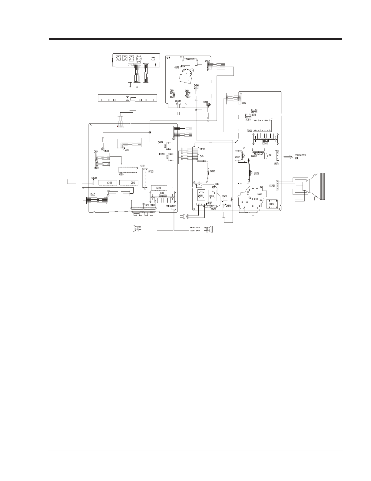
OVERVIEW
CON2K6
K
A
A
K
SVM COIL
Interconnect Diagram
The FA chassis was developed for consumer market purpose. This manual covers 27v True Flat CRT only. The
chassis is divided in two sections, the large signal board
is containing the deflection, dynamic focus, power supply circuitry & shutdown circuit. A second board, located on the left side of the figure, is employed for
processing the RF, audio, communication (main BUS),
deflection, IF and video signals, this chassis does not
require any other daughter board.
The Analog Flat chassis features a total of 9 IC’s on the
small signal board, for RGB signal, video switching, (HV
sync signal processing included). This chassis only supports the NTSC-U (USA) video format and this is made
trough the IC2200, P221-01519, main video processor
located on the middle of the small signal board, which is
taking care of the IF, AGC, OSD switching, YUV processing, Automatic Contrast Level Control Systems, SVM support, Audio/ Video & Chorma demodulation, including
Horizontal (East/West correction & X-ray protection) and
Vertical deflection signals. The IF signal come from the
WT1201, which is the main tuner.
A relationship between IC2200 and IC2990, P221-01438,
is linked, this last one is used for switching the video
signal inputs from the Front and Rear jacks. Also involved is the digital comb filter IC2400, 221-01449,
which is used to separate the Y and C signals from any
composite video (RF or Video In). The YUV input is processing directly through the IC2200.
The audio channels are applied to the audio processor
IC1400, 221-01127. The IC1400 is also processing the
TV- RF composite audio, this IC features function such
audio demodulation, SAP (second audio program), and
the audio processing for BASS, TREBLE and BALANCE adjustments, also includes the Surround and Soundrite features.
Once the audio is processed by IC1400, both channels
are applied to the main stereo amplifier. The IC800, P2211488, is the final audio stage and its signal is applied
to the speakers.
1-1 FA - GENERAL
Page 3
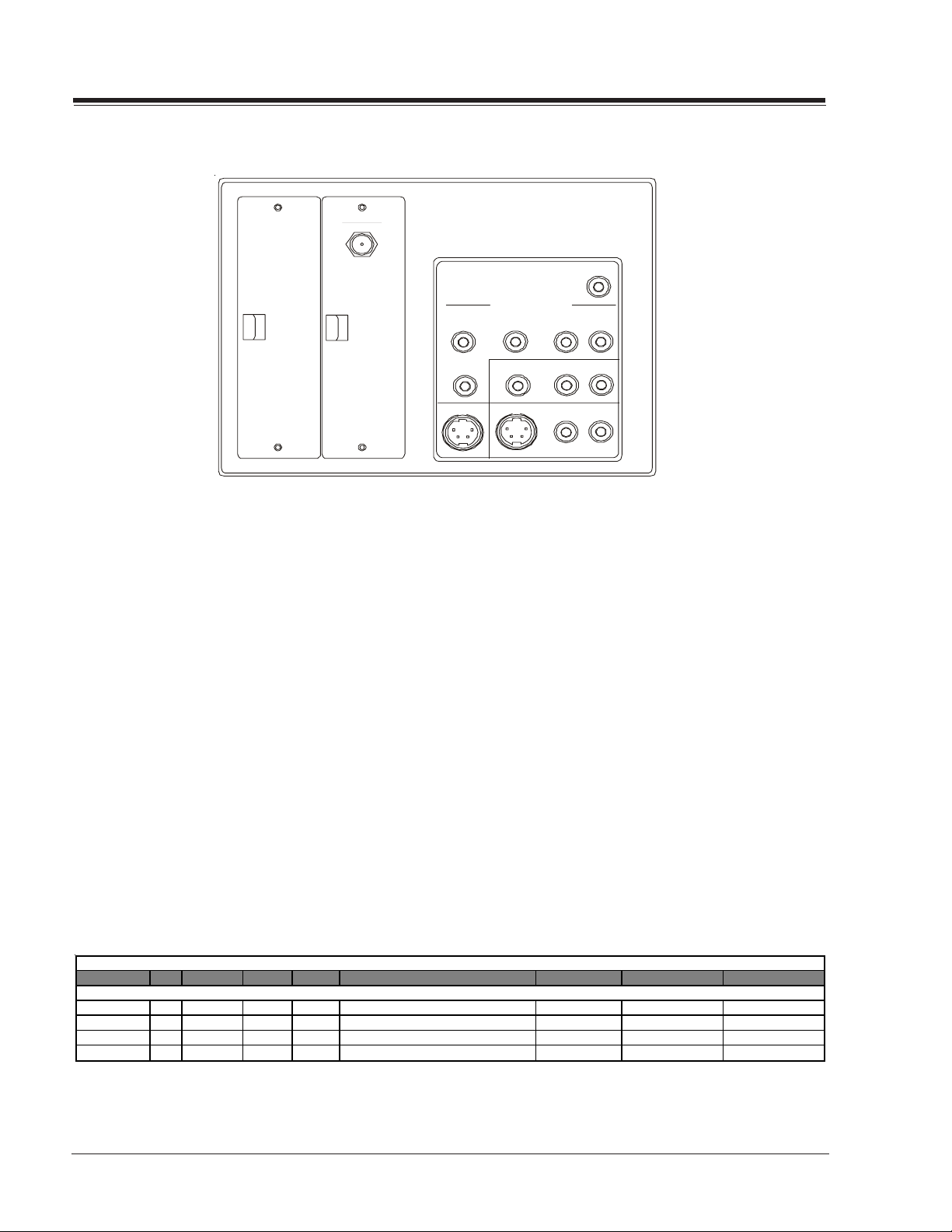
OVERVIEW
ANTENNA
CABL E
MATRIX OUT
The IC6000 is the 8 bits & 80K microcontroller and the
IC6001, 221-00745-05, is the EAROM memory. The
IC6000 handles the communication thru IIC BUS, I/O
ports, ADC converters for the keyboard, also supplies the
OSD signals for the On screen menus and the Close Caption decoding.
The main board is using three main linear regulators for
providing several voltage sources, the ICX3821 [5VSW]
for Tuner and IC2200 , ICX3820 [5VSB] for the IC6000/
1 and ICX3822 [9VSW] for most of the rest of IC’s. The
VSW stand for SWITCHED VOLTAGE, these regulators contain an internal power switch to turn them on/off, from
a Power Control signal provided by the IC6000.
Finally the main board has a provision for an additional
IC, for switching the YUV inputs. The objective of this
IC2902 is for adding an extra YUV input. This circuit
will be available for a future model.
RPr Pb
Y
S-VIDEO OUT
L
COMPONENT VIDEO I NPUT
VIDEO IN
S-VIDEO IN
R AUDIO IN L
R AUDIO IN L
R AUDIO IN L
On the large signal module there are five IC’s , the ICX3612
is the main power switching and PWM hybrid circuit and
in conjunction with ICX3702 made the main power regulation of this chassis. The purpose of this regulator is to
provide a proper protection for avoiding to shut the
main power supply off and therefore the complete TV set.
And of course, avoid the necessity of fuse replacement
due to a short circuit on the third party TV card.
The ICX2100 is the Vertical output amplifier and is processing the small signal provided by the IC2200 on the
small signal board. Also the IC3300 is processing the
EAST/WEST correction for the screen geometry.
Finally The IC5100 is used to amplify the RGB small signals from the IC2200 and then display them on the CRT
cathodes.
MODEL SCR CABINET F. JACKS R. JACKS EXTRA FEATURES
FA Chassis Model Information
ALL MODELS ARE MODULE LEVEL REPAIR
RP-29FA40-M 29 Table Top 4 13 TRUE FLAT, YUV INPUTS, AUTOVOLT
RP-29FA40-P 29 Table Top 4 13 TRUE FLAT, YUV INPUTS, AUTOVOLT
RP-29FA40-O 29 Table Top 4 13 TRUE FLAT, YUV INPUTS, AUTOVOLT
RP-29FA40-R 29 Table Top 4 13 TRUE FLAT, YUV INPUTS, AUTOVOLT
FA - GENERAL 1-2
REMOTE MICRO OP GUIDE
124-00233-P09 P221-01524-00 P206-04552
124-00233-P09 P221-01524-00 P206-04552
124-00233-P09 P221-01524-00 P206-04552
124-00233-P09 P221-01524-00 P206-04552
Page 4
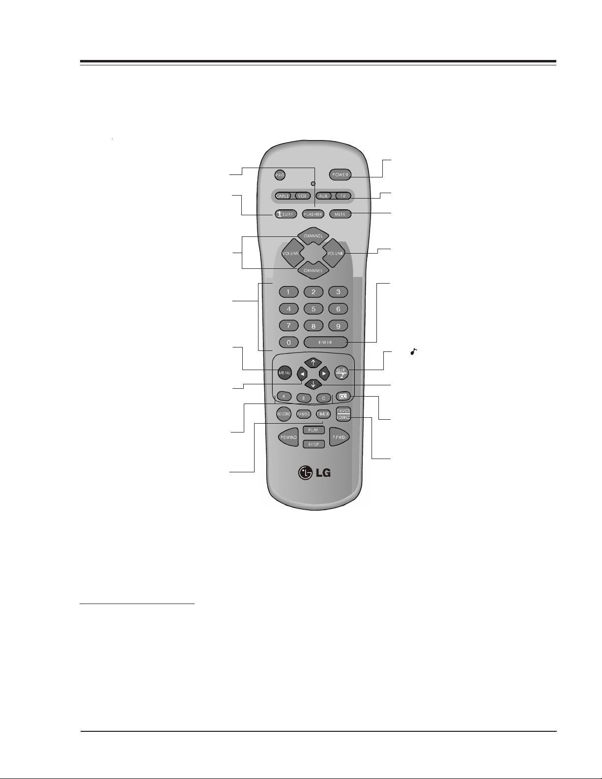
MBR3447LG MODEL REMOTE CONTROL
FLASHBK (Flashback)
Returns to previous Channel.
Turns Channel Preview On/Off.
When on, the Channel Up/Down
keys only Scroll through channels
selected in the Add/Del/Blnk.
SURF
POWER
Turns TV On or Off.
MODE
Selects the remote's mode of operation
MUTE
Turns sound Off and On
while picture remains.
CHANNEL (Up/Down)
Selects next channel in
TV’s memory. Press
and hold to repeat.
NUMBER PAD
Sele cts channels directly.
Displays menus for TV
and other options.
LEFT/RIGHT ARROWS
Chooses and shows the
desired menu option.
In commercial TV’s, doesn’t
have functionallity.
Displays the Sleep Timer menu.
Press repeatedly to set desired
TV shut-off time.
MENU
A, B, C Keys
TIMER
VOLUME (Left/Right)
Increases TV’s sound level.
ENTER
Shows Channel/Time, enters
channel, or removes any
on-screen menus.
QUIT/ (Three Functions Key)
It doesn’t function in commercial TV.
UP and DOWN ARROWS
Moves highlighted bar within
menu to select an option.
CC
Displays closed caption menu.
TV/VCR SOURCE
Steps through source options.
MBR3447LG
124-00233-P09
PROGRAMMING THE REMOTE
If you’re using Zenith products, the remote is already programmed for most common codes: TV= 101, VCR= 201,
CABLE=353, and AUX=401. For other brands, or if your
remote fails to control your Zenith products, you’ll have
to program the remote.
After installing the batteries, follow these steps for each
product:
1. Press and hold PRG using a blunt pointed object.
Release PRG after the indicator light turns on.
2. Press the device button to be programmed (CATV,
VCR, AUX, or TV).
3. Enter the 3-digit product code from chart on the
next page.
4. Press and release ENTER to save the code.
5. Point the remote at product and press POWER to
test the product’s operation. If it does not turn on,
reprogram remote using a different code.
6. Write the code on the label inside the battery
compartment for future reference.
1-3 FA - REMOTES
Page 5

REMOTE PROGRAMMING
AUTO FIND
If none of the codes in the code table operate your equipment, use Auto Find to search for the proper code.
1. Turn on the product you want to operate.
2. Press and hold PRG using a blunt pointed object.
Release PRG after the indicator ligth turns on.
3. Press any key to be programmed
4. Enter ”000”, then press ENTER within two seconds.
Auto Find is active after the indicator light flashes
and remains lit.
5. Point the remote at the product.
6. Press and release POWER repeatedly, about once a
second, until your products turns off. The indicator
light turns off when you press POWER and on when
you release it.
7. Press ENTER immediately to save the code. The
indicator light flashes to indicate the code has been
saved.
8. Press POWER to turn On your product.
9. Test your product. If the remote fails to operate
some of the basic functions, use Auto Find again to
search for a better code. (Auto Find resumes its
search after the last code that was entered and
saved in step 7).
NOTE: If the indicator light stays on as you press POWER,
Auto Find has tried all of the codes. If the product
you want to control has not turned off, your
remote will not work with that product. To cancel
Auto Find, press PRG at any time during Auto
Find.
CABLE BOX
This remote can control the cable/converter box volume
and muting (instead of the TV’s) is available on your
equipment.
1. Program the cable/coverter box normally.
2. After programming the cable/converter box. Press
and hold PRG again using a blunt pointed object.
Release PRG after the indicator light turns on.
3. Press and release the device button the cable box is
assigned to.
4.This time, enter the special code 3-9-9 instead of
the product code.
5. Press and release ENTER to save.
(CAT, VCR, AUX, or TV).
VOLUME OVERRIDE
These remotes can override TV, VCR, or Video Disk
Player volume functions with an amplifier’s volume and
muting.
1. Program the amplifier normally.
2. After programming the amplifier, Press and hold PRG
again using a blunt pointed object. Release PRG
after the indicator light turns on.
3. Press and release the device button whose volume
control is to be replaced by the amplifier volume
control. For example, pressing TV will operate the
amplifier’s volume while the remote is in TV mode.
4. This time, enter the special code 4-9-9 instead of
the product code.
5. Press and release ENTER to save.
AUXILIARY CAPABILITY
This remote can control up to seven devices. If the
remote has been programmed for four components
using the TV, VCR, CABLE, and AUX keys, you may also
program it for up to three additional using AUX+1,
AUX+2 and AUX+3
To Program AUX+1, AUX+2 AND AUX+3
1. Locate three digit code for product in code table.
2. Press and hold PRG until indicator lights up
3. Press the AUX and 1 simultaneously to select
AUX+1.
4. Enter the three-digit code and press ENTER. The
indicator light should flash and then turn off to
indicate the code has been accepted. If the light
stays on, repeat steps 3 and 4 or try a different
code.
5. Repeat steps 2-4 for AUX+2 and AUX+3.
6. Write the codes on the labels inside battery
compartment for future reference. Hold down AUX
and press 1,2 or 3 to access AUX+1, +2 or +3
mode.
UNIVERSAL ERASER 911
To restore the transmitter back to its initial default
settings, enter the Programming Mode as usual (by
holding PRG until the LED indicator lights), and press 9
1 1, followed by ENTER. The LED indicator will flash
three times to indicate that the transmitter has
returned to its initial default brand codes. Universal
Erase will work in any mode.
FA - REMOTES 1-4
Page 6
PROGRAMMING CODES
A
y
V
A
A
A
A
y
A
A
A
A
A
y
x
x
TV's Portland 246,727 SL Marx 326 Sears 936
Daewoo 149 ProScan 216,260,266, Sprucer 313 Sharp 441,442
Zenith 101,121,149 282,725 Stargate 326,379 Sherwood 449
152 Quasar 259,295 Standard Comp 335 Hitachi 950
TV/VCR
dventura TV/VCR 154 240,242,249, Tocom 317,318,346 Luxman 930
Daewoo TV/VCR 148 260,266,282, Unika 325,348,362 Magnavox 421,422,433,
Funai TV/VCR 154 283,284,285, Universal 325,358,362 434
Goldstar TV/VCR 153,172 286,287,288, Vid Tech 340 Son
Symphonic TV/VCR 154 708,710,711, Video Way 349 445,934
Zenith TV/VCR 150,153,154 725 Viewstar 327,354,355, Soundesign 461,498,901,
172 Realistic 212,213,265, 372 902
CR's Saisho 722 Zenith PM 374 Teac 418,419
dmiral 261 Salora 297 Technics 432
Akai 292,717,718, Sam sung 220,230
udio Dynamics 726 726 Chaparral 501,502 Zenith 460,461,498,
Bell + Howell 247 Sanyo 212,247,294 Cheyenne 502 901,902
Broksonic 221,250,255, Scott 243,290,729 Dishnet 515
Candle 727 265,274 GE 510,517 Citizen 914
Canon 704 Sharp 261,730 General Instrume nts 504,505 GE 916
Capeheart 728 Signature 2000 216,219,249 Hitachi 519,520 Goldstar 460,474
Citizen 727 Sony 232,723,724 Hughes Network 514 Hitachi 919
Craig 212 Sylvania 275,297 JVC 518 JVC 908
Curtis Mathes 259,266,725, Tatung 268,292 Macom 314 Kenwood 484
Daewoo 244,246,248, Teknika 272 Philips 521 Marantz 903,913
Daytron 246 297 ProScan 510,517 Nad 904
DBX 726 Vector Research 726,727 RCA DSS 373 Nakamic hi 493
Electrohome 730 Vic tor 726 RCA 510,517 Onkyo 471,906
Emerson 203,221,243, Video Concepts 726,727 Realistic 506 Opti mus 905
Fisher 211,212,213, 229 Sony 511 Quasar 912
GE 216,220,266, STS3 508 Sharp 483,917,918
Go Video 256,262,263,
Goldstar 253 Century 325 Zenith 351,378,500 902
Harman Kardon 296 Citizen 325 Toshiba 915
Hitachi 257,270,273, Comtroni c 326
JC Penney 268,726 GE 367
Jensen 292 Gemini 305,331,338
JVC 224,225,258, General Instrument 304,305,306, ADO 939
Kenwood 268,292,726, Hamlin 302,303,345, Denon 935 Pioneer 963
Magnavox 275 Jasco 325 Emerson 952 Toshiba 961
Marantz 267,268,726, Jerrold 304,307,308, Fisher 438,933,951 Zenith 960
Memore
MGA 297,730 Kale Vision 335 Hitachi 950
Mitsubishi 276,277,278, Macom 321 Kenwood 441, 931, 948
Montgomery W ard 216,219,249, 369,370 Marantz 929 ,947
Multitech 727 Panasonic 313,320 Mitsubishi 927
NEC 267,268,269, Philips 325,327,347, Nakamichi 925,926
Orion 250 Pioneer 315,343 Panasonic 431,432,945
Panasonic 245,251,259, RCA 341 Philips 421,433,434
Penta
Philco 275 337,364 RCA 437,943
Pioneer 210,282,726 Sig nal 326 Sanyo 438,439
719,720 Sansui 289,292,709,
729 Sears 211,212,213, Drake 503
727 Teac 268 Magnavox 521 Luxman 467
254,703,729 Toshiba 213,274,290, PrimeStar 513 Memorex 485
250,293,721, XR - 1000 243 Sierra I 502 Panasonic 912
722,729,730, Yamaha 726 Sierra II 502 Pioneer 470,485,907
731,732 Zenith 201,224,225, Sierra III 502 Proton 910
247,265,274 STS1 507 RCA 909
282,701,702,
725
700
292,705,706, Everquest 379 Sony 452 Victor 908
707,708 Garrard 325 Zenith 460,461,498,
268,292,299, 307,308,309,
726 310,318
727 365,366 Dynatech 953 Son
727 309,310,318, GE 932
212,298 360,363 Goldstar 460
279,280,296, Magnavox 327,334 JVC 949, 954
297,730 NSC 335,339,368, Luxm an 930
291,730 Oak 311,332,342 MCS 928
281,292,709, 350,352,354, Onkyo 923,924,946
726 355 Optim us 920,921,922
713,714,715, Regency 329 Pioneer 431,435,944
716 Samsung 326,335 Quasar 432
708,727 Scientific Atlanta 316,323,336, Radio Shack 431,441
Radio Shack 213,265,730 Teleview 326 JVC 949,954
RCA 216,220,228, Texscan 339,356,371 Kenwood 441,931,948
420,443,444,
730 Zenith HT-2000 353 Sylvania 433
SATELLITE
lphastar 516 Zenith CD Recor415
Yamaha 414,941,942
TUNER/AMP
CATV
llegro 358,362 Uniden 522 Son
llegro A-B Switch 361 United 344 491,492
rcher 325 Zenith Drake 312,328,330 Soundesign 461,498,901,
Toshiba 509,512 Sherwood 900
AUDIO - TAPE DECKS
Tec hnics 912
486,489,490,
COMPACT DISC 901,902
DC 940
DVD Players
iwa 938 JVC 965
kai 937 Mitsubishi 964
962
FA - REMOTES 1-5
Page 7
USER MENUS P221-01524-00
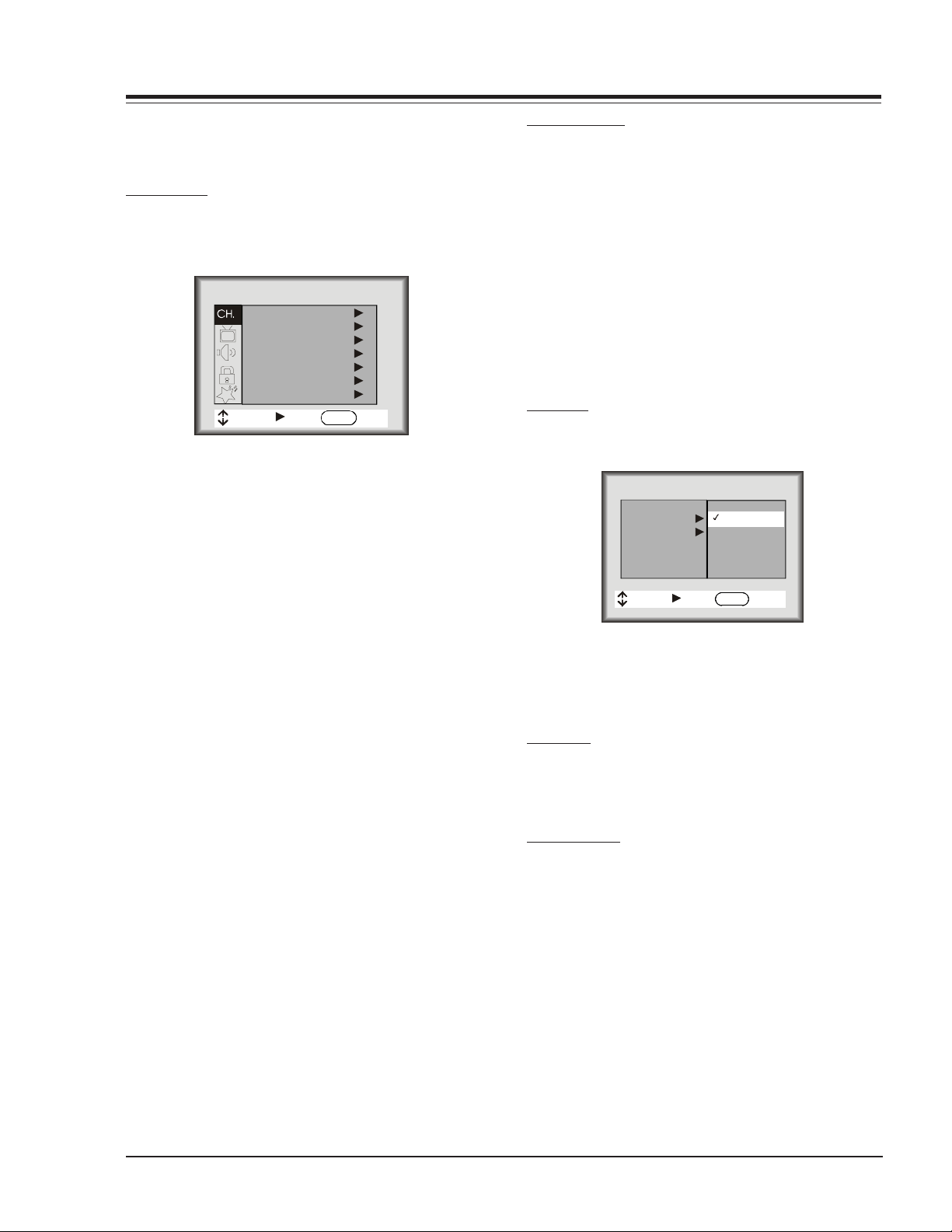
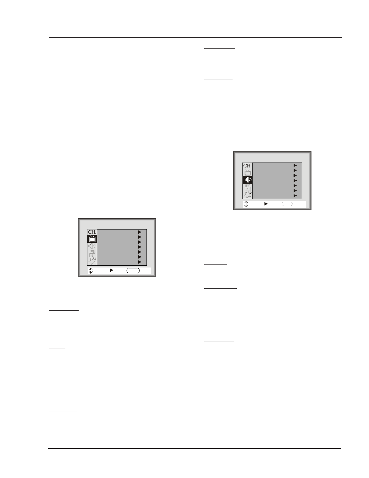
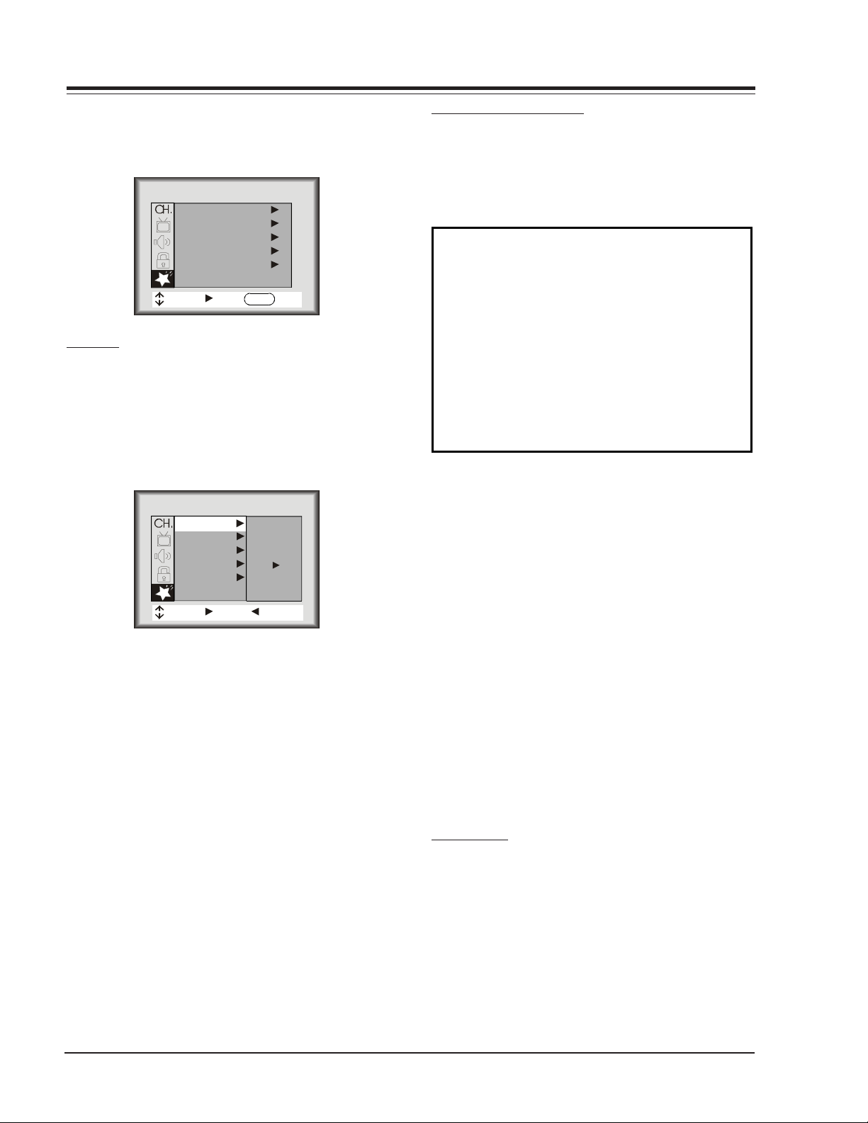
CHANNEL MENU
Below is the Channel Menu for the FA chassis with each
of its options.
EZ PROGRAM
The EZ Program feature automatically searches for all available channels and marks them as ‘Added’ so that they
may be accessed via the channel Up/Down key.
CHANNEL
EZ Program
Add/Del/Surf
EZ Clock
Captions
Caption/T
Language
Source
MOVE NEXT EXIT
In the EZ Program option, the current RF input type (Off
Air Antenna or Cable TV) is highlighted. Use the Up/
Down Arrow keys to change the RF input type.
To start the EZ Program, press the Right Arrow key. If the
Cable TV input type is selected, the EZ Program routine
will determine what type of cable system is present.
ext
ENTER
ADD/DEL/SURF
After running the Auto Program, all channels found by
the Auto Program feature will be marked ‘Added’. However, some of these channels may be scrambled, or undesired by the customer. The Add/Del/Surf feature allows the customer to selectively mark any channel as
‘Deleted’ or ‘Added’.
To change the status of a channel, press the Up/Down
Arrow keys.
To change the channel while adding or deleting channels, use the Channel Up/Down keys, or press the desired channel digits, followed by the ENTER key. If only
one channel is present, to change the channel the customer must use the digit keypad to select a channel.
EZ CLOCK
When the EZ Clock item is selected, pressing the Right
Arrow key allows entry into the clock set menu.
CLOCK
Clock Mo de
Time Set
MOVE MOVE NEXTNEXT BACKBACK
Manual
Manual
Auto
ENTERENTER
Notes:
• EZ Program clears all Surfing channels, which were
added.
• While searching for channels, all keys except for the
Power key are disabled. This prevents an incomplete
EZ Program procedure.
• Running the Auto Program will clear the factory mode,
if it was active. This happens at the end of the EZ
Program.
• If the EZ Program line in the Setup Menu is ‘red’, this
indicates that the module did not pass by Chassis.
When ‘green’, this indicates that the module did not
pass by Tracking. When ‘blue’, this indicates that the
module did not pass by Programming. To clear this
line to ‘white’, set the upper nibble of the EEPROM
location $1FFh to $B0h.
• If no channels are found then the following message
will appear: “Make sure that the cable/ant. is
connected, and try again.”
DAYLIGHT SAVINGS TIME
The customer also has the option of selecting the Daylight Savings Time to be On, Off or Auto using the Left/
Right Arrow keys.
CAPTIONS
This feature allows the customer to select: Off, On, or EZ
when Muted options.
To change the status of captions, press the Left/Right
Arrow key to select either On, Off, or EZ Mute.
CAPTION/TEXT
This feature allows the customer to activate or
desactivate Captions or Text.
Pressing the Left/Right Arrow keys sequentially through
each of the following Caption/Text options.
Caption 1 Caption 2 Caption 3 Caption 4
Text 1 Text 2 Text 3 Text 4
1-6 FA - MENUS
Page 8
USER MENUS P221-01524-00 (continued)
Notes:
• When the Text option is selected and a text box
appears, if the CC key is pressed, the Caption box
that allows setting to On, EZ Mute or Off will appear,
• When captions are being displayed, if one of the
Volume Up/Down keys is pressed, the volume bar will
not appear.
• When the Captions are not activated and the CC key
is pressed, the Caption Box will appear, that allows
choose On, EZ Mute or Off.
LANGUAGE
This feature allows the customer to change the menu
language to English, Spanish or French by pressing the
Up/Down Arrow keys.
SOURCE
This feature allows the customer to select: Antenna, Rear
Video, Rear-SV, Front Video, or Comp. Video.
PICTURE MENU
All menu items are adjusted with the Left/Right Arrow
keys.
COLOR TEMP
Sets the color temperature. The two settings are COOL
and WARM.
EZ PICTURE
This feature allows the customer to maintain 8 separate
Contrasts, Brightness, Color, Tint, Sharpness by setting
“Custom, Normal, Movie, Digital, Video Game, Sports,
Night Time, Weak Signal”.
SOUND MENU
All menu items are adjustment with the Left/Right Arrow
keys.
SOUND
Bass
Treble
Balance
Audio mode
Front Surr
EZ Soundrite
EZ Sound
MOVE NEXT EXIT
ENTER
PICTURE
Contrast
Brightness
Color
Tint
Sharpness
Color Temp
EZ Picture
MOVE NEXT EXIT
ENTER
CONTRAST
Contrast adjustment has 101 steps (0 to 100).
BRIGHTNESS
The brightness value sent to the video processor is (RfBrt
+ Customer Brightness) if the source is the RF source, or
(AuxBrt + Customer Brightness) if the source is the AUX
source. RfBrt and AuxBrt appears in the factory menu.
COLOR
Color adjustment has 101 steps (0 to 100). The color
value sent to the video processor is according to the
next equation and look up table.
TINT
Tint Adjustment has 101 steps (0 to 100). A center
mark indicates step 50. The tint value sent to the video
processor is (custom Tint + TintOffset)*127
SHARPNESS
Sharpness adjustment has 101 steps (0 to 100).The sharpness value is sent to the video processor as (Custom
Sharpness).
BASS
Bass adjustment has 101 steps (0 to 100).
TREBLE
Treble adjustment has 15 steps (0 to 14).
BALANCE
Balance adjustment has 29 steps (0 to 28).
AUDIO MODE
There are three audio modes available: Mono, Stereo, 2
Audio/SAP.
If 2nd Audio/SAP is selected, but the current channel
does not support SAP, then either Stereo or Mono will
be heard.
FRONT SURR
Front Surround can be set ‘ON’ or ‘Off’, regardless of the
current Audio Mode setting. However, the Front Surround effect can only be heard when the Audio Mode
has been set to ‘Stereo’ and a Stereo signal is present.
When this condition exists, there will be a short mute
(200ms) while toggling the Surround ‘On’ to ‘Off’, to
embellish Front Surround activation.
nd
1-7 FA - MENUS
Page 9
USER MENUS P221-01524-00 (continued)
EZ SOUNDRITE
The Sound Rite feature is used to obtain a uniform volume level, particularly while changing channels. The
Sound Rite feature can be best demonstrated on a channel with no signal (snow).
EZ SOUND
The EZ Sound Control has six selections the customer
can select. The selections available are: Custom, Normal,
Stadium, News, Music and Theater. The Left/Right Arrow
keys may be used to select any of the choices mentioned.
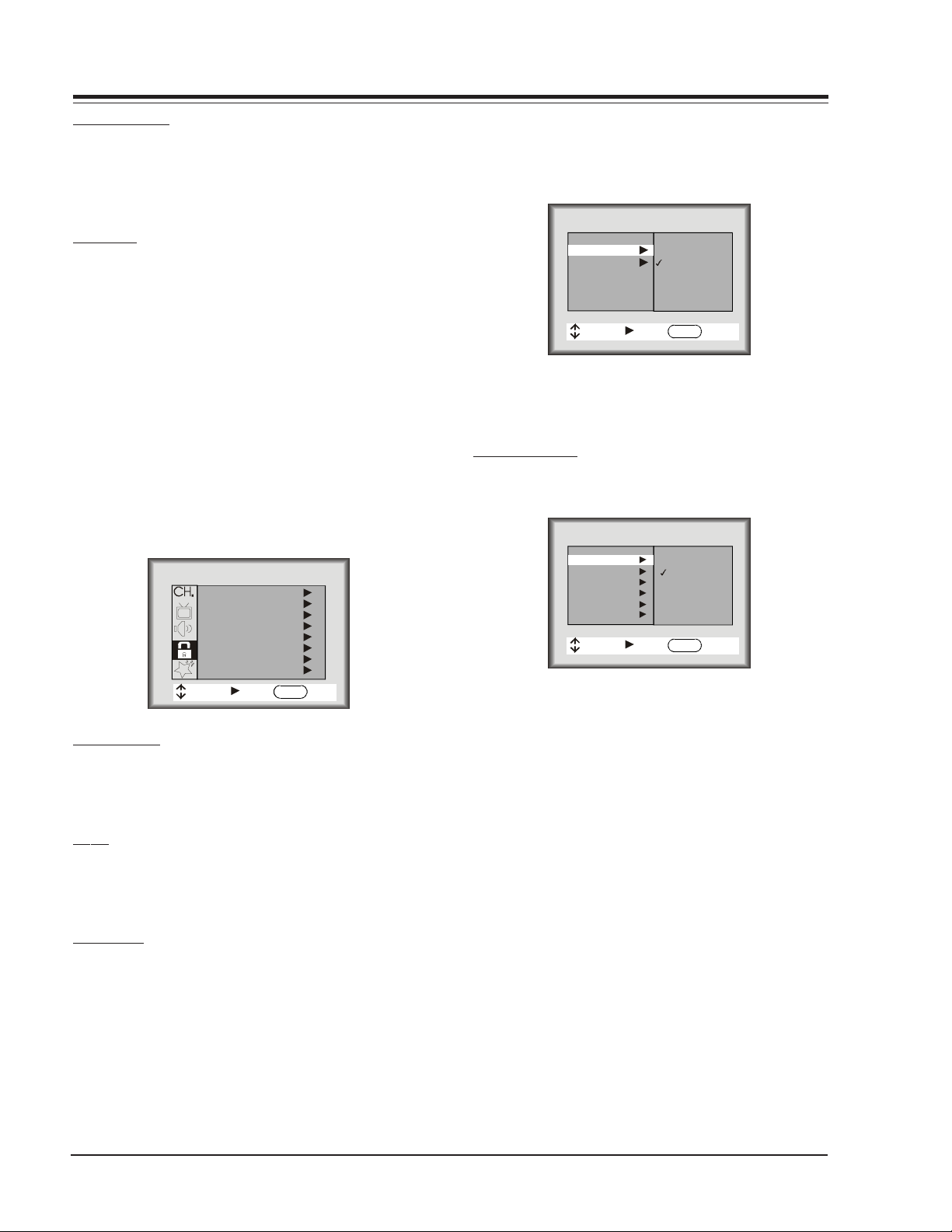
LOCK MENU
As show above, with the Lock Menu on-screen, use the
Up/Down arrow to highlight an option Like Content Blk,
then press ENTER.
Use the Up/Down/Left/Right arrows to select and adjust or set the rating for an option. For Sex Scenes for
example , use the “From TV-PG” setting. (See the Mini
Glossary, Ratings Charts on this and the previous page
for rating definitions).
LOCK
Aux Sources
MPAA
Age Block
Content Blk
Cdn. Ratings
Set Hours
Set Password
Lock On/Off
MOVE NEXT EXIT
AUX SOURCES
To Block or Unblock the sources, press the Up/Down Arrow keys.
The SOURCE key may be used to view the other source.
MPAA
The MPAA selector allows the customer to select either
to have the channel Unblocked, G and Above, PG and
Above, PG-13 and Above, R and Above, NC-17 and Above,
or X.
AGE BLOCK
Use the Right Arrow key to select the Age Block Menu.
Once entered into the Age Block Menu, the customer
has the option to block channels for general age or to
block channels for children.
ENTER
GENERAL BLOCK
To block channels for a general age, the customer may
either select: Unblocked, TV-G and Above, TV-PG and
Above, TV-14 and Above or TV-MA.
AGE
General
General
Children
MOVE NEXT BACK
Unblocked
TV-G
TV-PG
TV-14
TV-MA
ENTER
CHILDREN BLOCK
To block channels for children, select either: Unblocked,
TV-Y and Above or TV-Y7.
CONTENT BLOCK
To block a television program according to its content,
use the Right Arrow key to select the Content Block Menu.
CONTENT
Dialog
General
Language
Violence
Sex Scenes
F Violence
No Rating
MOVE NEXT BACK
Unblocked
TV-PG
TV-14
ENTER
DIALOG BLOCK
To block a television program with Dialog rating, use the
Up/Down Arrow keys to select either: Unblocked, TV-PG
and Above or TV-14.
LANGUAGE BLOCK
To block a television program with Language rating, use
the Up/Down Arrow keys to select either: Unblocked,
TV-PG and Above, TV-14 and Above, or TV-MA.
VIOLENCE BLOCK
To block a television program with Violence rating, use
the Up/Down Arrow keys to select either: Unblocked,
TV-PG and Above, TV-14 and Above, or TV-MA.
SEX SCENES BLOCK
To block a television program with Sex Scenes rating,
use the Up/Down Arrow keys to select either: Unblocked,
TV-PG and Above, TV-14 and Above, or TV-MA.
FA - MENUS 1-8
Page 10
USER MENUS P221-01524-00 (continued)
F VIOLENCE BLOCK
To block a television program with F Violence rating, use
the Up/Down Arrow keys to select either: Unblocked,
TV-Y7.
NO RATING BLOCK
To block a television program with No Rating , use the
Up/Down Arrow keys to select either: Unblocked and
Blocked.
CANADIAN RATINGS
Use the Right Arrow key to select the Content Block,
and use the Left/Right Arrow keys to select the Cnd.
English or Cdn. French.
CDN. RATINGS
Cdn. English
General
Cd. French
MOVE NEXT BACK
Exempt
Children
8+
General
PG
14+
18+
ENTER
SET HOURS
Use the Up/Down Arrow keys to adjust the number of
hours the Parental Control feature will be active. The
valid hour range is 1 through 99 hours.
SET PASSWORD
Press the Right Arrow key to allow Password entry.
TO ENTER PASSWORD
The software accepts four-digit codes only. The customer must enter a password
RE-ENTERING PARENTAL CONTROL MENU
If the Parental Control feature has been activated,
the software will not allow immediately entry into
the Parental Control Menu. Instead, it will prompt
for the correct password. If the correct password is entered, the Parental Control menu will
be unlocked so the user can change the configuration for parental options. If an incorrect
password is entered, an error message (“Not Accepted!) appears, and will not disappear until 5
seconds. This extended time provision increases
the amount of time necessary for a child to “crack”
the password.
Notes:
• The Parental Control menu will remain up for
15 seconds after the last key press.
• The QUIT key may be pressed to remove the PC
menu.
• Entry into the Factory Menu will immediately
turn off the PC feature
• The PC Hours and Password will be cleared
upon exit of the Parental Ctrl menu (unless
the Parental Ctrl feature has been turned on.)
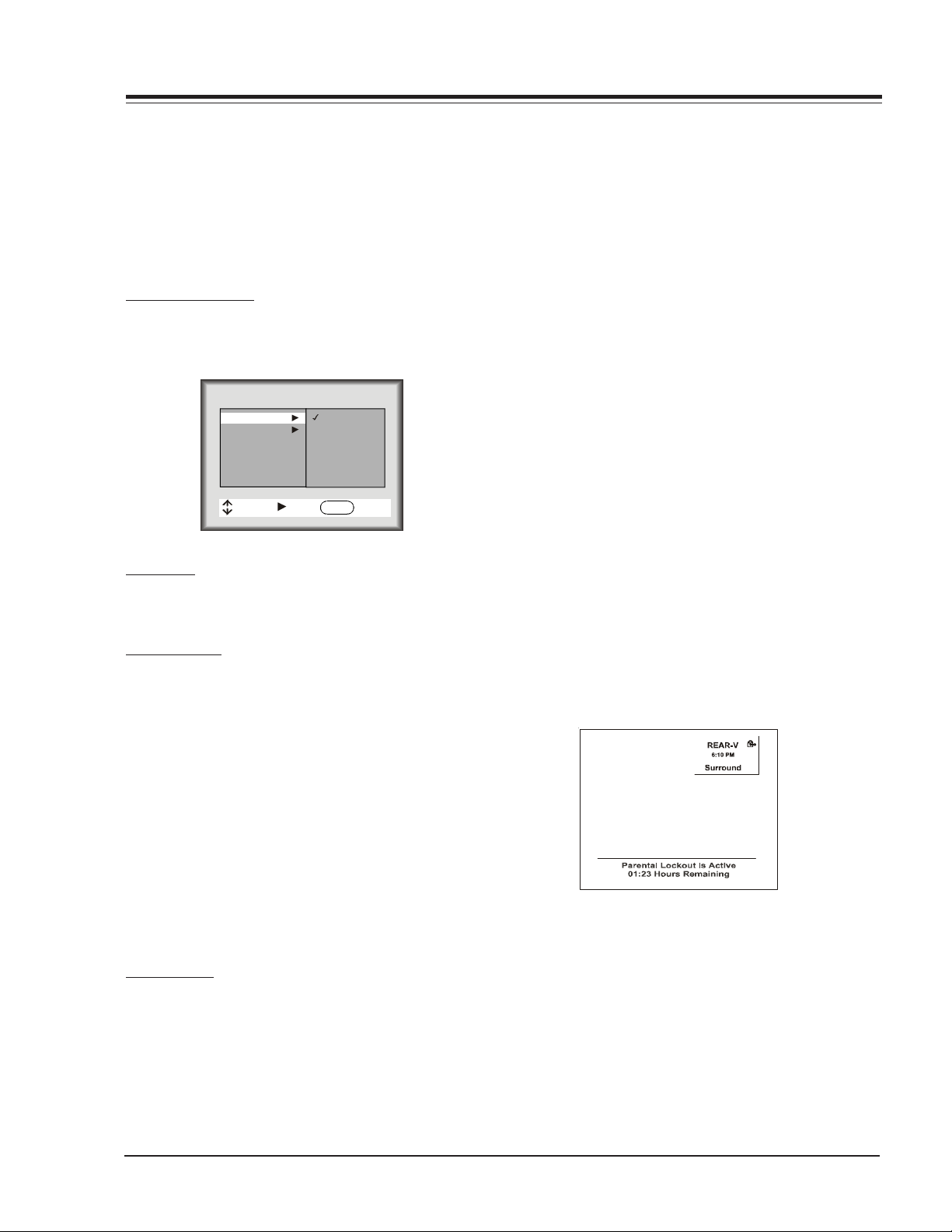
DISPLAY WHEN PARENTAL CONTROL IS ACTIVE
When the Parental Control has been activated
the channel is blocked. The display on the screen
shows two lines. The first line displays a message saying that the “PARENTAL LOCKOUT IS ACTIVE.”
The second line displays the amount of time (in
hours) left in the lockout.
REPEAT PASSWORD
After a four-digit code has been entered, the software
requires the customer to re-enter the same four-digit
code.
PASSWORD NOT ACCEPTED!
If an invalid code is entered, or the two codes entered
do not match, a blinking error message (“Not Accepted!”)
will appear. This error message also appears when no code
is entered for the password or if only one digit is entered and no other digit has been entered.
LOCK ON/OFF
This item turns the Parental feature On or Off. The Parental Ctrl. feature can only be turned on if the hours >
0, and a password has been set. Otherwise the Lock On/
Off line will display either of the following error messages: “Must Set Hours” or “Must Set Password.”
1-9 FA - MENUS
Page 11
USER MENUS P221-01524-00 (continued)
C
T
YTLC
C
LTMC
C
X
C
XMMT
C
C
C
SPECIAL MENU
This Menu contains the EZ Timer , Ch. Labels, XDS Display, EZ Demo and EZ Help.
SPECIAL
EZ Timer
CH. Labels
XDS Display
EZ Demo
EZ Help
MOVE NEXT EXIT
EZ TIMER
The Timer Menu contains the Sleep Timer and the On/Off
Timer features.
SLEEP TIMER
Sleep Timer (via Timer Menu)
The Left/Right Arrows can be used to adjust the current
sleep timer setting:
Off, 0:10, 0:20, 0:30, 1:00, 1:30, 2:00, 3:00 or 4:00
SPECIAL
EZ Timer
EZ Timer
CH. Labels
XDS Display
EZ Demo
EZ Help
MOVE NEXT BACK
ENTER
PRESS
TO SET
CHANNEL LABELS OPTION
This feature allows the customer to select a channel label for the current station. This channel label is displayed in the Channel/Time display. Initially, all channel
labels are set to ‘——‘, which results in no channel being displayed in the Channel/Time display.
CHANNEL LABELS
A&E CMTV ESPN HSE NOS TBN VC
AB
ACTS CNN E
AD
AMC CSPN FAM JCN QV
CNCB ESP2 HSN PBS TELE VCR
IC PLA
COM EWTN INSP PT
VH-1
VISN
TNN VJN
BCC CSP2 FNN LIFE RDS TNT WB
BET CTN FO
BRAV CTV F&V ME/U S
CA DIS F
CBC DIS
GALA MTV SHOW TWC YTV
CBN E! HBO NB
CBS EN
HN NICK TBS USA
MAX REQ TRAV WGN
TSN WTBS
SCFI TVA WWOR
SIN UPN ----
None
To change the current channel label, press the Up/Down
Arrow key.
To change the channel while adjusting channel labels,
use the Channel Up/Down keys, or press the desired channel digits, followed by ‘Enter’. (If Channel Up/Down is
pressed, the next or previous channel which was marked
‘Added’ will appear.)
ON/OFF TIMER
This feature consists of three menu lines: “On Time”,
“Off Time”, and “On/Off Timer”. This feature allows the
set to turn on and off at the times specified in “On
Time” and “Off Time”.
The “On Time” and “Off Time” are set identical to the
Clock Set feature in the Channel Menu.
An Off Time must be specified, before turning on the “EZ
Timer”—otherwise an error message (“Must Set On/Off”)
will be displayed on the On/Off Timer line.
The On/ Off Timer option turns the Timer On or Off.
If there is no Off Time set, then the On/Off Timer displays the above message saying: “Must Set Off Timer.”
Once the Off timer has been set, the customer can then
set the option to either On or Off.
FA - MENUS 1-10
Note:
• When in the channel label is selected ————, then
the Auto channel label is activated, in other words,
the program automatically take the channel label
of the signal that is send by broadcasting through
the XDS service.
• If the label None is selected, the Auto channel label
is disactivated.
XDS DISPLAY
Pressing the Left/Right Arrow Keys allows the customer
to select the XDS Display either On or Off.
Page 12
USER MENUS P221-01524-00 (continued)
EZ DEMO
The EZ Demo is designed to show-off the icon menus
and other icon displays on the sales floor. The EZ Demo
feature can be turned On/Off with the Up/Down Arrow
keys.
Initially, when the feature is activated, as soon as the
OSD times out, the EZ Demo will start. At this point,
pressing any key will temporarily disable the EZ Demo for
18 seconds, and if the EZ Demo is working and the Menu
key is pressed then the Special Menu will be displayed
and the EZ Demo feature will be selected allowing the
customer to disable it.
Note:
• The Auto Demo On/Off setting is not stored to the
EEPROM.
EZ HELP
The special features EZ Help option may be accessed using the Right Arrow key. The EZ Help feature provides
help on certain options and also provides support for
the EZ Programm, Add/Surf/Del, Degaussing, EZ Picture
and EZ SoundRite features. There is a simple explanation
of each options.
The EZ Help has a main screen called EZ Help. This screen
gives a solution to the most common problems that a
customer may encounter; i.e., To program channels.
MISC DISPLAYS
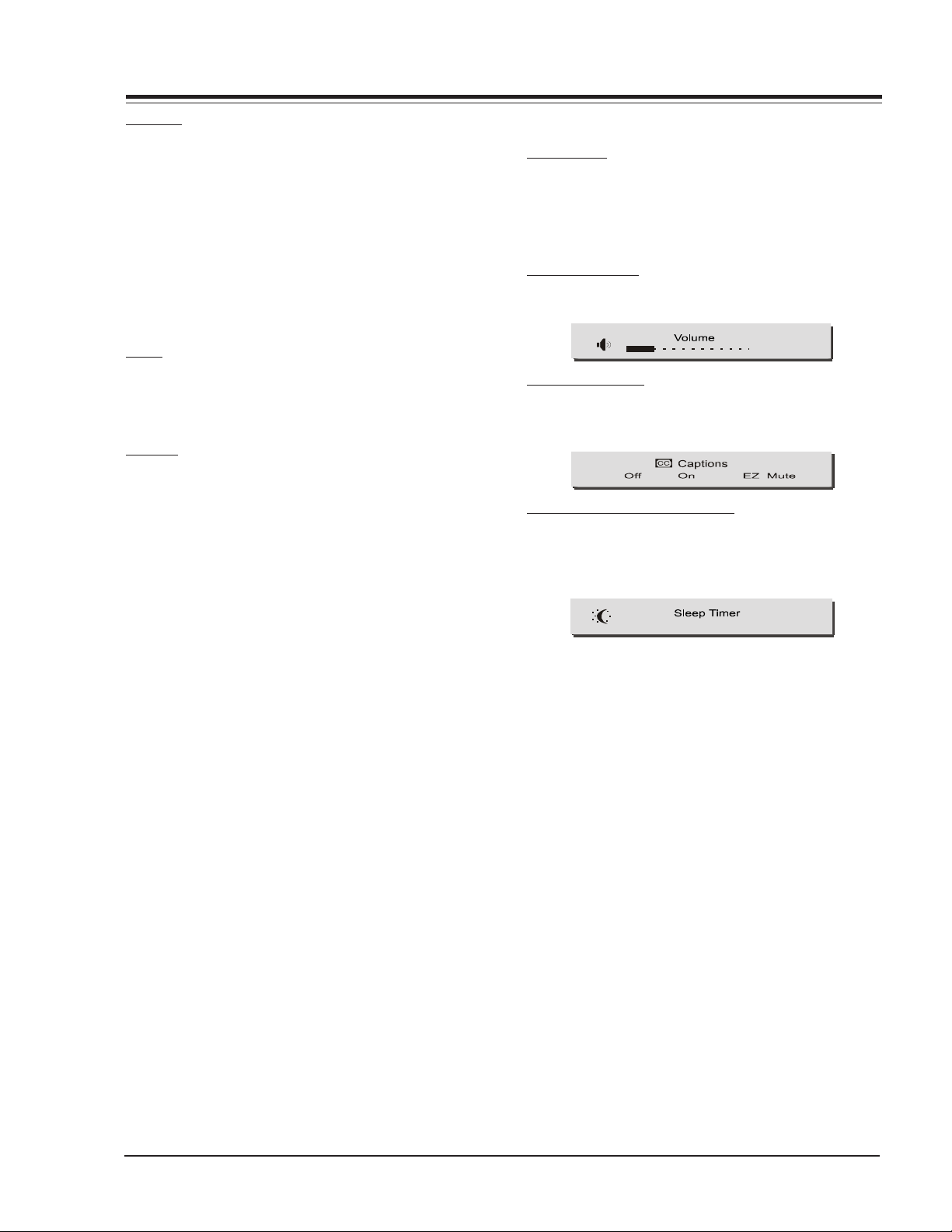
SLEEP TIMER
To press the timer key for activate the sleep timer.
The user can choose to activate the timer to turn off the
Television in 10, 20 or 30 minutes or 1, 1:30, 2,3 or 4
hours just by clicking on the sleep timer clock.
VOLUME DISPLAY
When the Volume key is pressed, the following display
appears on the screen.
23
CLOSED CAPTIONS
If the CC key is pressed the following displays appears.
The customer may change the settings of the Closed Captions to Off, On or EZMute
CHANNEL/TIME/AUDIO DISPLAY
Pressing the ENTER Key allows the customer to display
the channel, time audio mode as well as information of
the current program along with the rating of the program.
OFF
1-11 FA - MENUS
Page 13

FACTORY MENU
INSTALLERS MENU
Access the Installer’s Menu by using the remote control
or the keyboard on the front of the set.
With the remote: Press & Hold MENU key until the
Channel/Time display appears, then press 9, 8, 7, 6, and
ENTER.
With 6 button keyboard: Press and hold MENU until the
Channel/Time display appears. Simultaneously press the
VOLUME UP and CHANNEL DOWN keys.
Notes:
• When the factory mode is set to “1”, then
press ‘9’, ‘8’, ‘7’, and ‘6’, followed by
‘ENTER’ to access the Installer’s Menu.
• To acces the G2 re-adjustment mode, press 2 hold
the Menu key until the Channel/Time display appears,
then press ‘9’, ‘8’, ‘7’, ‘6’, and quit key.
00 Fact Menu: Use the Select key to select item #00,
which is the first item in the Installer’s Menu. The
Factory Mode item should always be left off (Zero is
off). When left in this mode, only items from 0 to 27
are visible. When the factory mode is set to 1, all menu
(Audio or Video settings) items will be available. Also
they will appear on the screen one at a time at the top
left of the screen.
When The Factory Mode is on, the Factory Menu line
appears at the middle of the screen to allow for proper
setting of the video.
When the Factory Mode is turned off, all TV functions
are returned to normal. The simbols at the top of the
channel menu icons is removed indicating that the
Factory Mode is off. There are 4 ways to turn off the
Factory Mode:
1. Change Installer’s Menu Item “00 F Mode” to 0.
2. Run Auto Program.
3. Use the Clock Set feature to set the time.
4. Use Factory off IR code.
Notes:
• Video Preference Settings Inhibited: In the Video
Menu, the Custom Video Preference settings are
inhibited while the Factory Mode is on and will
NOT be stored in EEPROM. (This allows the factory
to temporarily change the settings and not store
them permanently.)
01 Preset Px: Used to store the customer menu adjust-
ments in the nonvolatile memory of the EAROM. Settings for Contrast, Brightness, Color and Tint are
stored in this manner. 0 is Custom and 1 is Preset.
02 Preset Ax: Saves your custom audio settings
(Bass,treble,balance,audio mode,sound rite,front
surr,speaker) in nonvolatile memory (not affected by
power loss). Memory status is indicated by a 1 for
“custom settings already stored”, or 0 for “custom settings have not been stored.”
03 Vert Pos: Sets On Scree Display vertical position. Use
the ADJUST keys.
04 Horz Pos: Sets On Screen Display horizontal position.
Use the ADJUST keys.
05 Band/Afc: There are 8 possible settings for this op-
tion.
06 Ac on: Allows the TV to turn ON just by applying AC
power. Pressing the ON button is not necessary. This
is desirable when the TV is plugged into a cable box
or a power outlet controlled by a wall switch. Use adjust to select 0 or 1, where 0 is OFF and 1 is ON.
Note: When set to 1 (ON), the TV does not respond to
ON/OFF commands from either the remote or the
control panel, and the SLEEP TIMER is also
nonfunctional.
07 Feature Level: Set to 1 to see Zenith Code, when set
to 0 Private Codes are shown.
08 Trap: Turn On 3.58 MHz internal trap in Video Proces-
sor.
09 RF Band Pass Activates the Band Pass Filter for RF
(Antenna) input
10 RF BRT Set Black Level for RF input (Antenna)
11 Aux BRT Set Black Level for Auxiliar input (Video:
Composite & Y/C)
12Yuv BRT Set Black Level for YUV input (Component
Video)
13Max Bright Set maximum internal Brightness Register
14Max Contrast Set maximum internal Contrast Register
15 Vert Size: Vertical amplitude adjustment Variable in
factory menu. Range: 0-127, Initial value: 63.
16 Horz Size: Horizontal amplitude adjustment Variable
in factory menu. Range: 0-63, Initial value: 31.
17 Vert Phase: Adjust the Vertical Phase, screen up -
down. Range 0-5. Initial value: 0
18 Horz Phase: Adjust the Horizontal Phase, screen left-
right. Range: 0-31. Initial value: 32
19 Audio Level: Adjust the composite audio level aoutput
of the video processor.
20 RF AGC: Adjust the AGC delay for maximum gain with
a reference level of 0 dBmV.
2-1 FA - INSTALLERS MENU
Page 14

FACTORY MENU (continued)
21 Horz AFC: Set the automatic horizontal frecuency con-
trol on, should be 1.
22 WPL: Activates White Peak Limiter
23 Tint Offset: Set the Tint offset
24Red Cut: Set the Red Cutoff of Low Luminance White
Balance adjustment
25Green Cut: Set the Green Cutoff of Low Luminance
White Balance adjustment
26Blue Cut: Set the Blue Cutoff of Low Luminance White
Balance adjustment
27Green Gain: Set the Green Gain of High Luminance
White Balance adjustment
28Blue Gain: Set the Blue Gain of High Luminance White
Balance adjustment
29Air AFT: Set the AFT when watching air signal.
30 A ATT: Adjust the composite input level to the audio
decoder to have the standard input level.
31 A VCO: Adjust Stereo VCO and SAP VCO free running
frequency.
32 A Filter: Adjust the filter for Stereo, SAP and DBX.
45 H EHT Comp: Horizontal Extremely High Tension
Compesation. Range 0-7. Initial value: 4
46 V EHT Comp: Vertical Extremely High Tension
Compesation. Range 0-7. Initial value: 6
47DC Rest Set the DC Restoration level
48BLK Stretch Set the Black Stretch start point
49ABL Gain Set the Automatic Black Level Gain
50SVM GAIN Adjust the Scan Velocity Modulator gain
51SVM PH Adjust the Scan Velocity Modulator Phase
52ACB SW Activates Automatic Control Beam
53SHARP PF Sharpness peak frequency selection: 0 to
3.2 MHz and 1 to 4.0 MHz
54CORING Activates the enhancement of Sharpness from
1 to 2 MHz
55B-Y ATT Set the attenuation level of Cb of YUV signal
56R-Y ATT Set the attenuation level of Cr of YUV signal
57AUTO FLESH Activates the Flesh tone control
58 ABL START POINT Set the Automatic Black Level Start
Point
33 A Spectral: Adjust high frequency stereo separation
(3KHz.)
34 Wide Band: Adjust low frequency stereo separation
(300Hz.)
35 Max Blk. Hrs: Adjust the maximun number of hours
the TV can remain Blocked (even 99 hours)
36RGB Contrast: Set OSD Contrast level
37SUB Contrast: Set internal Sub-Contrast Register
38 EW Correct: East- West Correction. Range 0-63, Ini-
tial value:26
39 EW Top-Corr East-West Corner Correction (top). Range
0-31, Initial value: 14
40 EW Bott-Corr: East-West Corner Correction (bottom).
Range 0-31, Initial value: 23
41 EW Trap-Corr: East-West Trapezium Correction.Range
0-63. Initial value 30. Range 0-31, Initial value: 23
42 V Centering: Vertical Centering. Range 0-63. Initial
value: 30
43 V Linearity: Vertical Linearity. Range 0-15. Initial
value: 12
59Y GAMMA Set the non-linear Gamma curve for Lumi-
nance signal
60ACB PULSE P Set Automatic Control Beam Start Point
61SCREEN Not used
62AKB SETUP Mute the RGB Cathodes
63AUX BAND PASS Activates the Band Pass Filter for
Auxiliar (Composite, Y/C, YUV) input
64CD MATRIX Set the relative phase and amplitude of
Color response to demodulate de Chroma
65YCbCr Select the Demodulation System for Component
Video YUV or YCbCr
66C GAMMA Switch the Color Gamma
44 V S-Corr: Vertical S-Correction. Range 0-15. Initial
value: 11
FA - INSTALLERS MENU 2-2
Page 15
SERVICING
A
V
A
A
A
A
V
A
A
A
A
LARGE SIGNAL
POWER SUPPLY
The FA is a COLD chassis of a single sided circuit board,
developed for a 27”. The power supply section features
four IC’s for voltages sources. The FA chassis has the
capability to meet the Energy Star requirement for a
low power consumption on stand-by mode.
·9Volts, 1Amp ON/OFF Switch Regulator, 221-01460-07
·5Volts, 1Amp ON/OFF Switch Regulator, 221-01460-03
·5Volts, 0.150 Amp Switch Linear Regulator,
0IKE780500P
·Main regulator for Horizontal Deflection (B+), +15V,
Switch mode regulator 223-00061-01.
·Error amplifier 221-00265-03A.
+33VSW
+15VSB@100mA
HORIZONTAL
DRIVE
+5VSW@ 100m
+33VSW@ 15m
TUNER
SWITCH MODE REGULATOR
The FA chassis employs a switching power supply, quasiresonant topology type. The AC line is supplied thru
the bridge rectifier BRX3400 and CX3410 circuit through
the fuse FX3400 (5A @ 250 V fast blow), The AC operation range is between 90 Vrms to 135 Vrms (see TABLE
1.1) and a filter, consisting of LX3400, LX3401, CX3401,
CX3403 and CX3408, which is employed before the rectifier circuit to reduce noise from the AC line and vice
versa (EMI).
The voltage output of the rectifier, VDC, is supplied to
the Switch Mode Regulator Power Supply, and its output should be in this range [127 VDC to 352.5 VDC].
The SMPS consisting of ICX3612, ICX3701, ICX3702 and
the chopper transformer TX3600. Through 100 KOHM
resistor (Rst), RX3601 and CX3604 (Cst), which is derived the VCC from CX3410. These feed the pin 3 into
the internal zener diode located within ICX3612.
HV
-14VSW
205VSW
+35VSW
+12~14 VSW
6.3Vrms
6.3Vrms@315m
+130V@900mA
SWEEP
TRANSFORME
AC LINE
LINE
FILTER
RECTIFER
SECTION
MPI
SWITCHING
HYBRID IC
+5VSB@ 2mA
+12VSB@600mA
PROTECTION
+5VSB
OPTO
DEVICE
MICROPROCESSO
LSP
+21VL
+VAUD
+16VSB
+12VUP
SHUNT
REGULATOR
+5VSBF@27mA
+9VSW@ 120m
B+
+9VSW
+5VSW
+5VSBF
PWR CTRL
POWER SUPPLY BLOCK SCHEMATIC
ABL
+5VSW@ 70m
+VAUD@1400m A
PROCESS OR
ST AUDIO
IDEO
+5VSW@ 80m
COMB FILTER
+9VSW@ 50m
+9VSW@ 55m
+9VSW@ 5mA
+9VSW@ 70m
STEREO
SWITCH & VOL-
-14VSW@
ERTICAL
DEFLECTION
SWITCH ER
CXA2089S
FILAMENT
+14VSW@
3-1 FA - SERVICING
Page 16

SERVICING (continued)
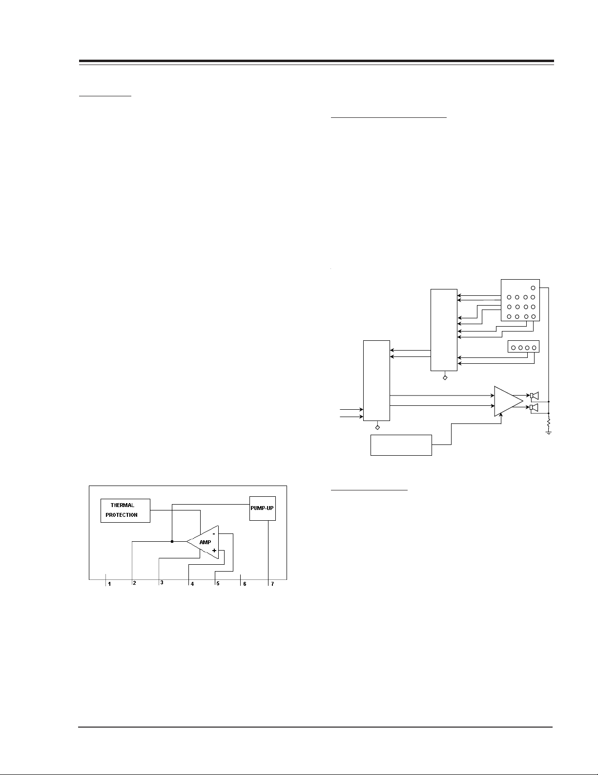
PIN DESCRIPTION
PIN # DESCRIPTION FUNCTION
1 POWER MOSFET DRAIN To drive the chopper xfmr,capable of switching a max of 650V.
2GROUND
3DRIVE
4 FEEDBACK
5SYNCHRONY
(HOT)
(+VCC)
(Vfb
(Vs/s
MOSFET Source connection.
Positive supply voltage, 32VDC
The output voltage error is applied to this pin.
External sync signal & Soft star capacitor.
At the same time this voltage is also applied to an internal comparator. So the voltage of this power source must
be within a set range, between a 5VDC reference (Vref)
and a 32VDC zener diode (Vz).
This set range is verified through the UVLO (Under Voltage Lock Out) circuit of the Switch Power IC.
START UP
When the VCC reaches a upper threshold voltage (15
VDC) the comparator switches to enable the ICX3612
including all internal bias circuits, control circuits, PWM
modulator & Power MOSFET.
Due the demand of energy from Cst and Rst the VCC voltage starts to fall. Before to fall too low, a bootstrap
winding on the power transformer (pins 13 & 16) reforces
adequately the VCC power to keep the full system operation.
VOLTAGE SOURCES
There are Five secondary windings on the TX3600 and
each has its own half wave rectifier.
Consequently there are Five stand-by DC voltages: B+,
24VAUD, 21VL, 16VSB & 12VUP.
The first is used to source the horizontal sweep circuit,
HOT (Horizontal Output Transistor). The second is used
for audio. The third is exclusively for the LSP source,
which is always on stand-by. The four is used for video
low signal processing and The fifth is used for
microcontroller.
The main microprocessor IC6000 and the EAROM memory
IC6001 are supplied by a five volts stand-by source,
+5V SB, which is derived through ICX3820 (0IKE78500P).
The +16 VSB and +12 VUP volts stand-by are protected
by fuses FX3613 and FX3614 ( 4A @ 125V) Very Fast
Acting, the +21VL and +24 VAUD volts stand-by are protected by fuses FX3611 and FX3612 ( 4A @ 125V) Slow
Blow. B+ as mentioned before are protected by the OCP
circuit. So they do not need fuse.
The FA chassis can be turn it on with the keyboard on
the front of the set or with the remote hand control.
The microcontroller IC6000 receive a signal and it output a high, about 4.8V, on pin 32 which is called PWRCTL. This pin is connected to RX3832, RX3831 and
RX3540; producing the +VAUD, +9VSW, +5VSW.
DEGAUSSING
The FA chassis employs a new method of degaussing,
which is performed through software. The IC6000 generate a pulse of about 1 second, time fixed, on pin 43.
This pin is set to high, about 4.8 VDC, through R3900,
4.7K 5% ¼watt. And it applies to Q3900, which drives
the 12 VCD relay KX3900. So the degaussing is performed
when the degauss coil is plugged to CN3T8 connector.
POWER SUPPLY ALIGNMENT PROCEDURES
ELECTRICAL ADJUSTMENT
The FA chassis SMPS does not need any manual measurement. All the output voltages are regulated through
ICX3702 (221-265-03A), error amplifier. The ICX3702
keeps the regulation using a reference voltage, through
a voltage divider. The voltage divider is formed by two
precision RX3706 and RX3704.
The values of these resistors depends of the B+ output
voltage.
NOTES:
·When servicing make sure to use a 120 VAC- 60Hz 25
Amp isolated source.
·Use a full white field on the video pattern generator.
FA - SERVICING 3-2
Page 17
SERVICING
DEFLECTION
HORIZONTAL
PINCUSHION CORRECTION CIRCUIT
This circuitry provides a east/west pincushion correction by providing a smaller horizontal deflection current
at the upper and lower portions of the flat screen, thru
the dual OP-AMP IC3300 . In addition, the overall horizontal width is adjusted using this circuit.
SHUTDOWN CIRCUIT
This shuthdown circuit operates by means of a sample of
HV taken from pin 3 of the sweep transformer TX3200.
This sample of voltage is rectified, filtered and then compared with a reference voltage (fixed by ZDX3002) by
the transistor QX3001. When the HV reaches the maximum permitted voltage, the transistor QX3001 enters in
conduction mode; like consequence the transistor QX3002
also enters in conduction too, switching a DC voltage
on pin 32 of IC2200.
When IC2200 receives this DC voltage, the X-ray protection is activated and the TV set is shutting off.
VERTICAL
The FA chassis uses a 221-01410 on ICX2100, which
contains; On-chip Thermal Protection, Pump-Up Stage
and Power Amplifier. The vertical drives comes from pins
13 & 14 from the video processor IC2200, which are a
negative and positive vertical Ramps. The Output to
the yoke is on PIN 2 of ICX2100 . Dual power supply is
needed for this IC (+/- 14Vdc), Applied on pins 6 & 1
respectively.
SMALL SIGNAL
AUDIO & VIDEO PROCESSING
The FA chassis has a stereo amplifier, IC800 P221-1488,
which is the final audio stage. This chassis does not
have phone output, however it has Matrix Output. The
Matrix output is used to connect a center speaker, in
serial with the two stereo speakers. This feature is used
to connect an additional 8 Ohm 10W speaker.
The stereo amplifier provides an power output of 10W x
2. The IC1400, 221-01127 is the audio processor and
provides the Bass, Treble, Balance, front surround and
soundrite features, this IC is controlled thru the IIC bus.
1510
AUDIO
AMPLIF
3
Pr
Y
SVout
SVin
IC800
TDA7263
8
REAR
JACK -
Matrix-
Pb R
VRL
SVin R
FRONT
JACK-
VR
Output
Output R
L
L
L
Comp. Audio In
AUX2-R
AUX2-
CXA2054S
19
41
42
IC1400
2
I C
39
40
7
6
IC6000
AUX1-
AUX1-
L
R OUTPUT
IC2900
CXA2089S
RV4
30
28
LV
A/V
SWITC
RV3
24
LV
22
RV2
17
LV
15
R
47
L
45
17
Hard
RV1
10
LV
8
2
I C
L
R INPUT
VIDEO PROCESSING
The IC2200, P221-01519 or TB1253AN/N is a TV Signal
Processor IC, which contains PIF,SIF, Video, Chroma
and deflection signal processors for NTSC systems. Also,
it has V and EW geometric correction Outputs.
Features
IF Stage.
Inter-carrier input.
Digital AFT
Tank coil less PIF VCO
Adjustment Free
Video Stage
Built-in AV Switch
Video monitor Output for CCD MCU
Built in chroma trap
Black stretcher, DL Aperture Control
Scan Velocity Modulation output.
3-3 FA - SERVICING
Page 18

SERVICING (continued)
ging
A
,
g
(
)
(
)
During the introduction of FA chassis the TA1253AN version was introduced, which is an upgrade from the N
version, the following is a comparison of both processors:
ITEM TB1253N
PIF block
PIF horizontal noise
AFT defeat (" IF lock" detection)
920 KHz beat
Y block
C-TRAP fo shift
Y linearity
Y white --> black rin
CHROMA block
TINT control center shift
TEXT block
CR input D range
Color Gain
uto flesh control range
DEF block
H output re-start frequency
H output stop timing
H AFC sensitivity
H VCO temperature drift
V-S correction
V wide BLK1 specification
V centering variable range
"H lock" detection
V skew performance
Read Bus "V lock"
"VP"
Data
- < Improve>
- -
38dB
+100KHz
OK Below Y 100%
10 de
ree
0.62 Vp-p
1
wide
14.7 KHz
Asyncronous
1.9 Hz/mV
-
+/-20%
EVEN: 9/8.5H, ODD 8.5/8H
(upper/lower)
+/-25%
"Lock-in" by Hsync 16 counts
-
"Vlock"
"Lock-out" by no Hsync 56 counts
TB1253AN
Specifications
45dB
below +20KHz
OK Below Y 130%
below 3degree
0.86 Vp-p
2 dB UP
narrow
15.7KHz
Stop when low lwvwl
2.5 Hz/mV
< Improve >
20%/-12%
EVEN: 9/9.5H, ODD 8.5/9H
(upper/lower)
+/-22%
-
"VP"
The IC2200 receives the video signal from the A/V switch
IC2990, P221-01438, which is switching the video signals from the Front and Rear jacks. Also involved is the
digital comb filter IC2400, 221-01449. The YUV input
is processing directly through the IC2200. The ABL circuit employed has been adjusted to allow to the IC2200
a maximum permissible Cathode current of 1.8 mA.
FA - SERVICING 3-4
Page 19

SERVICING
p
M
o
CrCb Ri Li
Ri
Li
i
Y/
Y/
Co
CRT
Y
o
k
e
Y/C loo
Ctrl
Ci
Y/
Cf
Ri Li
Vf Lf Rf
Y Main Sw
SUMMARY OF AUDIO/VIDEO SIGNALS
REAR JACK PACK:
YUV + LR Input (Component Video) … directly trough
Video Proc
Y/C + LR Input (Rear SVideo)
CV + LR Input (R Video)
Y/C loop + Matrix Output
FRONT JACK PACK:
Y/C or CV + LR Input (Front SVideo/Video)
CXA2089S SONY IC
48 pins DIP package with 9 DC Vcc
It drives 3 Y/C+LR and 3 CV+LR input, plus Y/C output
3 CV cross trough Comb filter and come back like Y/C
3-5 FA - SERVICING
Page 20

SERVICING (continued)
DIGITAL COMB FILTER
The IC2400 is the digital comb filter for NTSC-U format
it is a 1H, 2L Digital comb filter.
It separates luminance (Y) and chrominance (C) signals
from NTSC system composite video signal by using 2
horizontal (H) lines and delaying 1horizontal line on
memory.
This logical comb filter reduce color dot interference
and realizes high performance Y/C separation.
COMB FILTER CRITICAL SIGNAL
On the Pin 10 (Fsc) color sub carrier signal tuned to
3.58 Mhz for chrominance and luminance separation.
If this signal is not present the next problems could
be happened:
a) Color flicker
b) Chroma beat
c) Luminance signal noise
1
2
VIDEO OUTPUT
The RGB signals are applied to the IC5100, which is the
video RGB output.
IC5100 is triple Amplifier with fix gain equal to 51, operating at 9 Mhz of Bandwidth with small signal. It uses
one +Vcc equal or less of 200 DC Volts. AKB option is
not used for this model.
Using LR array the output is connected to its respective
Cathode
1
SCAN VELOCITY MODULATOR
This signal comes from directly from Video Processor
IC2200.
Three stages for signal are:
1: Class A NPN Amplifier
2: Complementary symmetry Driver
3: Complementary symmetry output Amp
Impedance coupling network connects to SVM coil in
CRT assembly.
YUV SWITCH PROVISION
FA chassis also has a provision to support an additional
YUV input thru IC2902, 74HC4053AP,but this is only a
provision. This IC is a 6x3 DEMUX controlled by control
signal sent by IC6000, MICOM. The outputs point to
rear jack’s YUV (Normally Closed inputs).
FA - SERVICING 3-6
Page 21

SERVICING
ADJUSTMENT PROCEDURE
SCOPE:
After change CPT or chassis make next arrangements.
1. – Initial Upload.
Menu Register name Value
Customer Customer Contrast 0
Customer Customer Br ightness 50
Factory RF Brightness 41
Factory Aux Brightness 41
Factory YUV Brightness 41
Factory Max Contrast 110
Factory Max Brightness 36
Factory Sub Co ntrast 6
Customer Co lor Temp Cool
Factory Red Cutoff 0
Factory Green Cutoff 0
Factory Blue Cutoff 0
Factory Green Gain 63
Factory Blue Gain 60
Customer Co lor Temp War m
Factory Red Cutoff 0
Factory Green Cutoff 0
Factory Blue Cutoff 0
Factory Green Gain 63
Factory Blue Gain 51
WHITE BALANCE ADJUSTMENT
a) Set any video source without signal (channel label
will remain)
b) Set Chromatics as Normal
c) Set Customer Brightness at 85
d) Observe what color is most noticeable: Red, Green or
Blue
e) Push <9,8,7,6,MENU> to enter at Factory menu;
change the value “FACT MENU” (register #0) from 0
to 1 to get at all registers.
f) Charge into the Factory registers from 24 to 28 the
respective values looking into the tables of Cool &
Warm.
Cool Color Temp values:
“x” = 0.282 +/- 0.008, “y” = 0.288 +/- 0.008, “T” =
10,000 °K +/- 1000
CPT
Response
Red 0 30 14 63 60
Green 30 0 21 64 60
Blue 37 38 0 62 60
#24 Red
Cutoff
#25 Green
Cutoff
#26 Blue
Cutoff
#27 Green
Gain
#28 Blue
Gain
WARM Color Temp values:
“x” = 0.295 +/-0.008, “y” = 0.305+/-0.008, “T” = 8,000
°K +/- 1000
G2 (SCREEN) ADJUSTMENT
a) Set Chromatics as Normal
b) Set Customer Contrast at 0
c) Set Customer Brightness at 15
d) Set any channel without RF signal
e) Push <MENU> key at remote control until it display
channel label
f) Push <9,8,7,6,QUIT> to display Horizontal Line (it
will remain by 3 minutes)
g) Turn G2 control at Sweep (FBT) in clock wise to make
noticeable the line and after turn counter clock wise
to make it lightly visible.
h) Push <QUIT> to exit
i) Set again Normal Chromatic and available channel
CPT
Response
#24 Red
Red 0 31 14 63 53
Green330 216250
Blue 42 39 0 63 53
Cutoff
#25 Green
Cutoff
#26 Blue
Cutoff
#27 Green
Gain
#28 Blue
Gain
RF SUB-BRIGHTNESS ADJUSTMENT
a) Set LG 10 Step pattern.
0 123456789
<= Grey Scale
<= Color Bars
b) Change values of Factory registers #10 and #11 (RF &
AUX BRT respectively) to 31 and register #12 YUV
BRT to 21. Retouch register #10 to have 3rd step half
illuminated. Set RF and AUX equal and YUV lower
10 units.
c) Push <9,8,7,6,MENU> to enter at Factory menu;
change the value “FACT MENU” (register # 0) from 1
to 0 to disable the Factory Menu.
d) Set again Normal Chromatic and available video source
TINT ADJUSTMENT
a) Customer Tint register is fixed for all EZ pictures,
therefore Tint adjustment is not required.
3-7 FA - SERVICING
Page 22

SERVICING (continued)
EZ PICTURE VALUES FOR VIDEO PROCESSOR
a) If it necessary to review the values of Chromatics for each EZ Picture, next tables have entire description.
b) Check the Video Processor IC type: TB1253N uses Tint Offset register at 5; and TB1253AN uses Tint Offset
register at 0.
Video Processor IC: TB1253N
Tint offset will be " 5 "
RF, CV & Y/C S ources
Contr ols Nor mal Movie Digital Vi deo Game S port Nig ht Ti me Weak S i g nal
Cont ra s t 100 70 100 67 80 27 67
Brightn es s 50 57 60 57 35 70 54
Color 65 6065 555762 59
Tin t 0 0 0 2 R 4G 0 0
Sharpne s s 85 85 100 77 80 80 40
Color Temp Cool Warm Cool Cool Cool Warm Cool
YUV Source
Contr ols Nor mal Movie Digital Vi deo Game S port Nig ht Ti me Weak S i g nal
Cont ra s t 100 70 100 67 80 27 67
Brightn es s 50 57 60 57 35 70 54
Color 65 6065 556059 64
Tin t 0 0 0 2 R 4G 0 0
Sharpne s s 85 85 100 77 80 80 40
Color Temp Cool Warm Cool Cool Cool Warm Cool
EZ picture values for Video Processor IC: TB1253AN
Tint offset will be " 0 "
RF, CV & Y/C S ources
Contr ols Nor mal Movie Digital Vi deo Game S port Nig ht Ti me Weak S i g nal
Cont ra s t 100 70 100 67 80 27 67
Brightn es s 50 57 60 57 35 70 54
Color 50 5053 454650 51
Tint 0 0 0 2R 4G 0 0
Sharpne s s 85 85 100 77 80 80 40
Color Temp Cool Warm Cool Cool Cool Warm Cool
YUV Source
Contr ols Nor mal Movie Digital Vi deo Game S port Nig ht Ti me Weak S i g nal
Cont ra s t 100 70 100 67 80 27 67
Brightn es s 50 57 60 57 35 70 54
Color 47 4750 424644 49
Tint 0 0 0 2R 4G 0 0
Sharpne s s 85 85 100 77 80 80 40
Color Temp Cool Warm Cool Cool Cool Warm Cool
FA - SERVICING 3-8
Page 23

SERVICING
IF AND AUDIO SERVICING
AGC DELAY
With a strong noise-free antenna signal, adjust with left
select key the RF AGC (#20) to a lower setting until the
signal gets noiser. Increase the setting again (with right
select key) for a noise-free picture.
AUDIO LEVEL ADJUSTMENT
a) Apply a RF signal with good video and audio at
100Hz at 100% modulation.
b) Access item #19 AUDIO LEVEL on the service menu.
c) Place a high impedance meter on pin #19 of IC1400
or the positive side of capacitor C1427. Adjust with
left/right select keys the AUDIO LEVEL register to 250
mVrms.
MTS DECODER ALIGNMENT.
The purpose of this procedure is adjusting registers of
SONY audio decoder and sound processor CXA2054S
(IC1400).
Initial conditions:
a) Alignment should be accomplished at least ten min utes after the TV set have been turned on.
b) TV sound must be set for flat response (EZ sound in
Normal).
c) Audio mode must be set for Stereo.
d) Use 8 ohm resistive loads instead of the speakers.
e) Open RM1416 and RM1417 in order to disconnect
the RF audio signal.
f) Connect a Multiplex Modulator to negative of capaci
tor C1427.
Five register of the audio processor should be adjusted.
Bits TEST-DA and TEST1 should be set according with
the current adjust.
Inside of the service menu:
·To see TEST-DA and TEST1 registers enter the “B” key of
the remote control (TESTDA= “0” and TEST1 = “0” are
conditions for normal operation), then ten bits regis
ters will display in the bottom of the screen, upper of
tree rows (see the figure 1). The first one is TESTDA
register and the second one is TEST1 register.
·To change the state of TESTDA and TEST1 push the
“QUIT” key of the remote control.
ATT ADJUSTMENT
a) Set the chassis for RF input.
b) Set bits TEST-DA = “0” and TEST1 = “0”.
c) Input a 100 Hz signal at 25 KHz deviation (100 %
mod.), 75 us off to pin 19 of IC1400.
d) Adjust with right/left select keys the A ATT register
(item #30) for 490 mVrms (± 10 mVrms) in TVOUT-L
output, pin 44 of IC1400.
STEREO, SAP VCO ADJUSTMENT
a) Set bits TEST-DA = “1” and TEST1 = “0”.
b) Monitor the TVOUT-R output frequency (pin 43 of
IC1400) in a no input state.
c) Adjust with right/left select keys the A VCO register
(item #31) of IC1400 so that frequency is as close to
62.936 KHz (± 0.5 KHz) as possible.
STEREO, SAP DBX FILTER ADJUSTMENT
a) Set bits TEST-DA = “0” and TEST1 = “1”.
b) Input 9.4 KHz, 600mVrms to COMP-IN pin 19 of
IC1400.
c) While monitoring the STATUS FLAG (FILADJ bit, see
figure 2) of IC1400, adjust with right/left select keys
the A FILTER register (item #32). Align with the cen
ter of the FILADJ = 1 (Adjustment OK) condition range
(see figure 2).
ADJUSTMENT POINT
FILTER
0
1
0
Figure 2 A FILTER adjustment.
SEPARATION ADJUSTMENT
REGISTER
63
FILADJ
FLAG
a) Set bits TEST-DA = “0” and TEST1 = “0”.
b) Set volume at maximum.
c) Set a stereo signal, 300 Hz at 12.9 KHz deviation (30
% mod.), left channel only, dbx ON at pin 19 of IC1400.
d) Adjust with right/left select keys the WBAND register
(item#34) to reduce right speaker output at the mini
mum.
e) Set the frequency only of SIF signal to 3 KHz.
f) Adjust with right/left select keys the SPECTRAL regis
ter (item #35) to reduce right speaker output at the
minimum.
3-9 FA - SERVICING
Page 24

COMPONENT PARTS LIST
LOCATION PART NUMBER DESCRIPTION
CAPACITOR
C1202 022-08309-12A CAPACITOR ;100 MFD 20% 16V ;ELECTROLYTIC, 1 SECT
C1204 022-08312-07A CAPACITOR ;4.7 MFD 20% 50V ;ELECTRO LYTIC, 1 SECT
C1209 022-08309-15A CAPACITOR ;470 MFD 20% 16V ;ELECTROLYTIC, 1 SECT
C1210 022-08312-01A CAPACITOR ;0.22 MFD 20% 50V ;ELECTROLYTIC, 1 SECT
C1213 022-08309-12A CAPACITOR ;100 MFD 20% 16V ;ELECTROLYTIC, 1 SECT
C1216 022-08312-08A CAPACITOR ;10 MFD 20% 50V ;ELECTROLYTIC, 1 SECT
C1217 022-08312-08A CAPACITOR ;10 MFD 20% 50V ;ELECTROLYTIC, 1 SECT
C1218 022-08312-03A CAPACITOR ;0.47 MFD 20% 50V ;ELECTROLYTIC, 1 SECT
C1233 022-08312-04A CAPACITOR ;1 MFD 20% 50V ;ELECTROLYTIC, 1 SECT
C1235 022-08309-15A CAPACITOR ;470 MFD 20% 16V ;ELECTROLYTIC, 1 SECT
C1236 022-08312-07A CAPACITOR ;4.7 MFD 20% 50V ;ELECTRO LYTIC, 1 SECT
C1238 022-08257-12A CAPACITOR ;1000 PFD 10% 50V ;CERAMIC DISC
C1413 022-08312-07A CAPACITOR ;4.7 MFD 20% 50V ;ELECTRO LYTIC, 1 SECT
C1414 022-08312-04A CAPACITOR ;1 MFD 20% 50V ;ELECTROLYTIC, 1 SECT
C1415 022-07669-15A CAPACITOR ;10 MFD 10% 50V ;ELECTROLYTIC, 1 SECT
C1416 022-08188-05A CAPACITOR ;10 MFD 20% 25V ;NON PLZD ELECTROLYTIC
C1417 022-07669-14A CAPACITOR ;3.3 MFD 10% 50V ;ELECTRO LYTIC, 1 SECT
C1418 022-08049-20A CAPACITOR ;0.047 MFD 10% 50V ;POLYESTER
C1419 022-08257-17A CAPACITOR ;2700 PFD 10% 50V ;CERAMIC DISC
C1420 022-08188-05A CAPACITOR ;10 MFD 20% 25V ;NON PLZD ELECTROLYTIC
C1421 022-08312-07A CAPACITOR ;4.7 MFD 20% 50V ;ELECTRO LYTIC, 1 SECT
C1422 022-08188-05A CAPACITOR ;10 MFD 20% 25V ;NON PLZD ELECTROLYTIC
C1423 022-08309-12A CAPACITOR ;100 MFD 20% 16V ;ELECTROLYTIC, 1 SECT
C1425 022-08312-07A CAPACITOR ;4.7 MFD 20% 50V ;ELECTRO LYTIC, 1 SECT
C1426 022-08312-08A CAPACITOR ;10 MFD 20% 50V ;ELECTROLYTIC, 1 SECT
C1427 022-08312-07A CAPACITOR ;4.7 MFD 20% 50V ;ELECTRO LYTIC, 1 SECT
C1428 022-08312-04A CAPACITOR ;1 MFD 20% 50V ;ELECTROLYTIC, 1 SECT
C1429 022-08049-13A CAPACITOR ;0.012 MFD 10% 50V ;POLYESTER
C1430 022-08257-21A CAPACITOR ;5600 PFD 10% 50V ;CERAMIC DISC
C1431 022-08188-05A CAPACITOR ;10 MFD 20% 25V ;NON PLZD ELECTROLYTIC
C2 022-08312-07A CAPACITOR ;4.7 MFD 20% 50V ;ELECTROLYTIC, 1 SECT
C2104 022-08049-24A CAPACITOR ;0.10 MFD 10% 50V ;POLYESTER
C2109 022-08049-24A CAPACITOR ;0.10 MFD 10% 50V ;POLYESTER
C2111 022-08312-08A CAPACITOR ;10 MFD 20% 50V ;ELECTROLYTIC, 1 SECT
C2112 022-07786C C APAC ITOR ;1000 PFD 10% 500V ;CERAMIC DISC
C2202 022-08312-01A CAPACITOR ;0.22 MFD 20% 50V ;ELECTROLYTIC, 1 SECT
C2206 022-08309-12A CAPACITOR ;100 MFD 20% 16V ;ELECTROLYTIC, 1 SECT
C2211 022-08312-08A CAPACITOR ;10 MFD 20% 50V ;ELECTROLYTIC, 1 SECT
C2215 022-08312-03A CAPACITOR ;0.47 MFD 20% 50V ;ELECTROLYTIC, 1 SECT
C2217 022-08312-09A CAPACITOR ;22 MFD 20% 50V ;ELECTROLYTIC, 1 SECT
C2219 022-08312-08A CAPACITOR ;10 MFD 20% 50V ;ELECTROLYTIC, 1 SECT
C2224 022-08312-05A CAPACITOR ;2.2 MFD 20% 50V ;ELECTRO LYTIC, 1 SECT
C2226 022-08310-11A CAPACITOR ;47 MFD 20% 25V ;ELECTROLYTIC, 1 SECT
C2227 022-08227-19A CAPACITOR ;0.47 MFD 5% 50V ;POLYESTER
C2229 022-08312-08A CAPACITOR ;10 MFD 20% 50V ;ELECTROLYTIC, 1 SECT
C2236 022-08312-04A CAPACITOR ;1 MFD 20% 50V ;ELECTROLYTIC, 1 SECT
C2406 022-08312-08A CAPACITOR ;10 MFD 20% 50V ;ELECTROLYTIC, 1 SECT
C2409 022-08309-11A CAPACITOR ;47 MFD 20% 16V ;ELECTROLYTIC, 1 SECT
C2410 022-08312-07A CAPACITOR ;4.7 MFD 20% 50V ;ELECTRO LYTIC, 1 SECT
C2412 022-08309-11A CAPACITOR ;47 MFD 20% 16V ;ELECTROLYTIC, 1 SECT
C2413 022-08312-07A CAPACITOR ;4.7 MFD 20% 50V ;ELECTRO LYTIC, 1 SECT
C2414 022-08309-11A CAPACITOR ;47 MFD 20% 16V ;ELECTROLYTIC, 1 SECT
C2424 022-08312-08A CAPACITOR ;10 MFD 20% 50V ;ELECTROLYTIC, 1 SECT
C2427 022-08312-08A CAPACITOR ;10 MFD 20% 50V ;ELECTROLYTIC, 1 SECT
C2901 022-08312-08A CAPACITOR ;10 MFD 20% 50V ;ELECTROLYTIC, 1 SECT
C2902 022-08312-04A CAPACITOR ;1 MFD 20% 50V ;ELECTROLYTIC, 1 SECT
C2904 022-08312-04A CAPACITOR ;1 MFD 20% 50V ;ELECTROLYTIC, 1 SECT
C2908 022-08312-04A CAPACITOR ;1 MFD 20% 50V ;ELECTROLYTIC, 1 SECT
C2911 022-08312-04A CAPACITOR ;1 MFD 20% 50V ;ELECTROLYTIC, 1 SECT
C2914 022-08309-15A CAPACITOR ;470 MFD 20% 16V ;ELECTROLYTIC, 1 SECT
C2915 022-07958-38 CAPACITOR ;390 PFD 5% 100V ;CERAMIC CHIP
FA - COMPONENT PARTS LIST 4-1
Page 25

COMPONENT PARTS LIST
LOCATION P ART NU MBER DESCRIPTION
C2926 022-08309-13A CAPACITOR ;220 MFD 20% 16V ;ELECTROLYTIC, 1 SECT
C2927 022-08312-08A CAPACITOR ;10 MFD 20% 50V ;ELECTROLYTIC, 1 SECT
C2928 022-08312-08A CAPACITOR ;10 MFD 20% 50V ;ELECTROLYTIC, 1 SECT
C2961 022-08312-08A CAPACITOR ;10 MFD 20% 50V ;ELECTROLYTIC, 1 SECT
C2963 022-08312-08A CAPACITOR ;10 MFD 20% 50V ;ELECTROLYTIC, 1 SECT
C2964 022-08312-08A CAPACITOR ;10 MFD 20% 50V ;ELECTROLYTIC, 1 SECT
C2969 022-08309-12A CAPACITOR ;100 MFD 20% 16V ;ELECTROLYTIC, 1 SECT
C2975 022-08257-12A CAPACITOR ;1000 PFD 10% 50V ;CERAMIC DISC
C3200 022-08242-26A CAPACITOR ;47 PFD 10% 50V ;CERAMIC DISC
C3202 022-08257-08A CAPACITOR ;470 PFD 10% 50V ;CERAMIC DISC
C3207 022-08049-16A CAPACITOR ;0.022 MFD 10% 50V ;POLYESTER
C3220 022-07786-10C CAPACITOR ;470 PFD 10% 500V ;CERAMIC DISC
C3222 022-07786-10C CAPACITOR ;470 PFD 10% 500V ;CERAMIC DISC
C3227 022-07877-12 CAPACITOR ;0.1 MFD 10% 250V ;POLYESTER
C3300 022-08310-16 CAPACITOR ;1000 MFD 20% 25 V ;ELECTROLYTIC, 1 SECT
C3301 022-08257-08A CAPACITOR ;470 PFD 10% 50V ;CERAMIC DISC
C5104 022-07877-12 CAPACITOR ;0.1 MFD 10% 250V ;POLYESTER
C5106 022-08318-04A CAPACITOR ;1 MFD 20% 350V ;ELECTROLYTIC, 1 SECT
C5109 022-07523-01B CAPACITOR ;0.01 MFD +80 % & -20 % 2000V ;CERAMIC DISC
C5111 022-08317-08 C APACITOR ;10 MFD 20% 250V ;ELECTROLYTIC, 1 SECT
C5112 022-07523-01B CAPACITOR ;0.01 MFD +80 % & -20 % 2000V ;CERAMIC DISC
C5114 022-08309-13A CAPACITOR ;220 MFD 20% 16V ;ELECTROLYTIC, 1 SECT
C5115 022-08310-12A CAPACITOR ;100 MFD 20% 25V ;ELECTROLYTIC, 1 SECT
C5500 022-07877-12 CAPACITOR ;0.1 MFD 10% 250V ;POLYESTER
C5501 022-08317-08 C APACITOR ;10 MFD 20% 250V ;ELECTROLYTIC, 1 SECT
C5502 022-07877-12 CAPACITOR ;0.1 MFD 10% 250V ;POLYESTER
C5503 022-08228-11A CAPACITOR ;0.1 MFD 10% 50V ;POLYESTER
C5504 022-08228-11A CAPACITOR ;0.1 MFD 10% 50V ;POLYESTER
C5505 022-08310-12A CAPACITOR ;100 MFD 20% 25V ;ELECTROLYTIC, 1 SECT
C5507 022-08049-16A CAPACITOR ;0.022 MFD 10% 50V ;POLYESTER
C5508 022-08247-22A CAPACITOR ;33 PFD 5% 50V ;CERAMIC DISC
C5509 022-08228-11A CAPACITOR ;0.1 MFD 10% 50V ;POLYESTER
C5510 022-08242-34A CAPACITOR ;100 PFD 10% 50V ;CERAMIC DISC
C5511 022-08242-34A CAPACITOR ;100 PFD 10% 50V ;CERAMIC DISC
C5512 022-08049-16A CAPACITOR ;0.022 MFD 10% 50V ;POLYESTER
C5513 022-08049-16A CAPACITOR ;0.022 MFD 10% 50V ;POLYESTER
C5514 022-08309-11A CAPACITOR ;47 MFD 20% 16V ;ELECTROLYTIC, 1 SECT
C5515 022-08309-11A CAPACITOR ;47 MFD 20% 16V ;ELECTROLYTIC, 1 SECT
C5516 022-08306-22A CAPACITOR ;33 PFD 10% 500V ;CERAMIC DISC
C5517 022-08315-08 C APACITOR ;10 MFD 20% 160V ;ELECTROLYTIC, 1 SECT
C6019 022-08312-07A CAPACITOR ;4.7 MFD 20% 50V ;ELECTROLYTIC, 1 SECT
C6022 022-08312-04A CAPACITOR ;1 MFD 20% 50V ;ELECTROLYTIC, 1 SECT
C6026 022-08049-24A CAPACITOR ;0.10 MFD 10% 50V ;POLYESTER
C6030 022-08309-13A CAPACITOR ;220 MFD 20% 16V ;ELECTROLYTIC, 1 SECT
C6034 022-08312-05A CAPACITOR ;2.2 MFD 20% 50V ;ELECTROLYTIC, 1 SECT
C6035 022-08049-24A CAPACITOR ;0.10 MFD 10% 50V ;POLYESTER
C6077 022-08312-07A CAPACITOR ;4.7 MFD 20% 50V ;ELECTROLYTIC, 1 SECT
C800 022-08312-16 CAPACITOR ;1000 MFD 20% 50V ;ELECTROLYTIC, 1 SECT
C801 022-08228-11A CAPACITOR ;0.1 MFD 10% 50V ;POLYESTER
C803 022-08310-11A CAPACITOR ;47 MFD 20% 25V ;ELECTROLYTIC, 1 SECT
C811 022-08312-04A CAPACITOR ;1 MFD 20% 50V ;ELECTROLYTIC, 1 SECT
C812 022-08310-11A CAPACITOR ;47 MFD 20% 25V ;ELECTROLYTIC, 1 SECT
C813 022-08228-11A CAPACITOR ;0.1 MFD 10% 50V ;POLYESTER
C814 022-08311-16 CAPACITOR ;1000 MFD 20% 35V ;ELECTROLYTIC, 1 SECT
C821 022-08312-04A CAPACITOR ;1 MFD 20% 50V ;ELECTROLYTIC, 1 SECT
C822 022-08310-11A CAPACITOR ;47 MFD 20% 25V ;ELECTROLYTIC, 1 SECT
C823 022-08228-11A CAPACITOR ;0.1 MFD 10% 50V ;POLYESTER
C824 022-08311-16 CAPACITOR ;1000 MFD 20% 35V ;ELECTROLYTIC, 1 SECT
CM1201 022-08368-20A CAPACITOR ;10,000 PFD 10% 25V ;CERAMIC CHIP, LDLESS
CM1203 022-08368-20A CAPACITOR ;10,000 PFD 10% 25V ;CERAMIC CHIP, LDLESS
CM1207 022-08352-28A CAPACITOR ;47 PFD 5% 50V ;CERAMIC CHIP, LDLESS
CM1208 022-08352-38A CAPACITOR ;120 PFD 5% 50V ;CERAMIC CHIP, LDLES S
4-2 FA - COMPONENT PARTS LIST
Page 26

COMPONENT PARTS LIST
LOCATION PAR T NUM BER DESCRIPTION
CM1211 022-08366-08A CAPACITOR ;1,000 PFD 10% 50V ;CERAMIC CHIP, LDLESS
CM1212 022-08366-08A CAPACITOR ;1,000 PFD 10% 50V ;CERAMIC CHIP, LDLESS
CM1214 022-08366-08A CAPACITOR ;1,000 PFD 10% 50V ;CERAMIC CHIP, LDLESS
CM1215 022-08352-24A CAPACITOR ;33 PFD 5% 50V ;CERAMIC CHIP, LDLESS
CM1224 022-08366-08A CAPACITOR ;1,000 PFD 10% 50V ;CERAMIC CHIP, LDLESS
CM1225 022-08368-20A CAPACITOR ;10,000 PFD 10% 25V ;CERAMIC CHIP, LDLESS
CM1226 022-08366-08A CAPACITOR ;1,000 PFD 10% 50V ;CERAMIC CHIP, LDLESS
CM1227 022-08366-08A CAPACITOR ;1,000 PFD 10% 50V ;CERAMIC CHIP, LDLESS
CM1230 022-08366-08A CAPACITOR ;1,000 PFD 10% 50V ;CERAMIC CHIP, LDLESS
CM1231 022-08366-08A CAPACITOR ;1,000 PFD 10% 50V ;CERAMIC CHIP, LDLESS
CM1234 022-08368-20A CAPACITOR ;10,000 PFD 10% 25V ;CERAMIC CHIP, LDLESS
CM1236 022-08366-08A CAPACITOR ;1,000 PFD 10% 50V ;CERAMIC CHIP, LDLESS
CM1411 022-08370-22A CAPACITOR ;15,000 PFD 10% 16V ;CERAMIC CHIP, LDLESS
CM1412 022-08370-24A CAPACITOR ;22,000 PFD 10% 16V ;CERAMIC CHIP, LDLESS
CM1424 022-08376-32A CAPACITOR ;100,000 PFD +80% & -20% 16V ;CERAMIC CHIP, LDLESS
CM1432 022-08366-18A CAPACITOR ;6,800 PFD 10% 50V ;CERAMIC CHIP, LDLESS
CM1433 022-08366-18A CAPACITOR ;6,800 PFD 10% 50V ;CERAMIC CHIP, LDLESS
CM1434 022-08370-22A CAPACITOR ;15,000 PFD 10% 16V ;CERAMIC CHIP, LDLESS
CM2200 022-08352-17A CAPACITOR ;16 PFD 5% 50V ;CERAMIC CHIP, LDLESS
CM2201 022-08366-12A CAPACITOR ;2,200 PFD 10% 50V ;CERAMIC CHIP, LDLESS
CM2203 022-08376-32A CAPACITOR ;100,000 PFD +80% & -20% 16V ;CERAMIC CHIP, LDLESS
CM2204 022-08352-36A CAPACITOR ;100 PFD 5% 50V ;CERAMIC CHIP, LDLESS
CM2205 022-08376-32A CAPACITOR ;100,000 PFD +80% & -20% 16V ;CERAMIC CHIP, LDLESS
CM2208 022-08376-32A CAPACITOR ;100,000 PFD +80% & -20% 16V ;CERAMIC CHIP, LDLESS
CM2209 022-08376-32A CAPACITOR ;100,000 PFD +80% & -20% 16V ;CERAMIC CHIP, LDLESS
CM2210 022-08376-32A CAPACITOR ;100,000 PFD +80% & -20% 16V ;CERAMIC CHIP, LDLESS
CM2212 022-08376-32A CAPACITOR ;100,000 PFD +80% & -20% 16V ;CERAMIC CHIP, LDLESS
CM2216 022-08352-40A CAPACITOR ;150 PFD 5% 50V ;CERAMIC CHIP, LDLESS
CM2218 022-08352-28A CAPACITOR ;47 PFD 5% 50V ;CERAMIC CHIP, LDLESS
CM2223 022-08370-24A CAPACITOR ;22,000 PFD 10% 16V ;CERAMIC CHIP, LDLESS
CM2225 022-08368-20A CAPACITOR ;10,000 PFD 10% 25V ;CERAMIC CHIP, LDLESS
CM2230 022-08376-32A CAPACITOR ;100,000 PFD +80% & -20% 16V ;CERAMIC CHIP, LDLESS
CM2231 022-08352-22A CAPACITOR ;27 PFD 5% 50V ;CERAMIC CHIP, LDLESS
CM2232 022-08366A CAPACITOR ;220 PFD 10% 50V ;CERAMIC CHIP, LDLESS
CM2233 022-08376-32A CAPACITOR ;100,000 PFD +80% & -20% 16V ;CERAMIC CHIP, LDLESS
CM2234 022-08376-32A CAPACITOR ;100,000 PFD +80% & -20% 16V ;CERAMIC CHIP, LDLESS
CM2235 022-08376-32A CAPACITOR ;100,000 PFD +80% & -20% 16V ;CERAMIC CHIP, LDLESS
CM2237 022-08376-32A CAPACITOR ;100,000 PFD +80% & -20% 16V ;CERAMIC CHIP, LDLESS
CM2240 022-08376-32A CAPACITOR ;100,000 PFD +80% & -20% 16V ;CERAMIC CHIP, LDLESS
CM2241 022-08370-24A CAPACITOR ;22,000 PFD 10% 16V ;CERAMIC CHIP, LDLESS
CM2242 022-08352-44A CAPACITOR ;220 PFD 5% 50V ;CERAMIC CHIP, LDLESS
CM2401 022-08352-14A CAPACITOR ;12 PFD 5% 50V ;CERAMIC CHIP, LDLESS
CM2402 022-08352-22A CAPACITOR ;27 PFD 5% 50V ;CERAMIC CHIP, LDLESS
CM2403 022-08352-22A CAPACITOR ;27 PFD 5% 50V ;CERAMIC CHIP, LDLESS
CM2404 022-08368-20A CAPACITOR ;10,000 PFD 10% 25V ;CERAMIC CHIP, LDLESS
CM2405 022-08368-20A CAPACITOR ;10,000 PFD 10% 25V ;CERAMIC CHIP, LDLESS
CM2407 022-08368-20A CAPACITOR ;10,000 PFD 10% 25V ;CERAMIC CHIP, LDLESS
CM2408 022-08368-20A CAPACITOR ;10,000 PFD 10% 25V ;CERAMIC CHIP, LDLESS
CM2411 022-08368-20A CAPACITOR ;10,000 PFD 10% 25V ;CERAMIC CHIP, LDLESS
CM2415 022-08352-38A CAPACITOR ;120 PFD 5% 50V ;CERAMIC CHIP, LDLESS
CM2416 022-08352-42A CAPACITOR ;180 PFD 5% 50V ;CERAMIC CHIP, LDLESS
CM2417 022-08368-20A CAPACITOR ;10,000 PFD 10% 25V ;CERAMIC CHIP, LDLESS
CM2418 022-08368-20A CAPACITOR ;10,000 PFD 10% 25V ;CERAMIC CHIP, LDLESS
CM2419 022-08352-31A CAPACITOR ;62 PFD 5% 50V ;CERAMIC CHIP, LDLESS
CM2421 022-08366-16A CAPACITOR ;4,700 PFD 10% 50V ;CERAMIC CHIP, LDLESS
CM2422 022-08352-24A CAPACITOR ;33 PFD 5% 50V ;CERAMIC CHIP, LDLESS
CM2423 022-08352-18A CAPACITOR ;18 PFD 5% 50V ;CERAMIC CHIP, LDLESS
CM2426 022-08368-20A CAPACITOR ;10,000 PFD 10% 25V ;CERAMIC CHIP, LDLESS
CM2800 022-08376-32A CAPACITOR ;100,000 PFD +80% & -20% 16V ;CERAMIC CHIP, LDLESS
CM2801 022-08376-32A CAPACITOR ;100,000 PFD +80% & -20% 16V ;CERAMIC CHIP, LDLESS
CM2802 022-08376-32A CAPACITOR ;100,000 PFD +80% & -20% 16V ;CERAMIC CHIP, LDLESS
CM2803 022-08376-32A CAPACITOR ;100,000 PFD +80% & -20% 16V ;CERAMIC CHIP, LDLESS
CM2804 022-08376-32A CAPACITOR ;100,000 PFD +80% & -20% 16V ;CERAMIC CHIP, LDLESS
FA - COMPONENT PARTS LIST 4-3
Page 27

COMPONENT PARTS LIST
LOCATION PART NUMBER DESCRIPTION
CM2805 022-08376-32A CAPACITOR ;100,000 PFD +80% & -20% 16V ;CERAMIC CHIP, LDLESS
CM2806 022-08376-32A CAPACITOR ;100,000 PFD +80% & -20% 16V ;CERAMIC CHIP, LDLESS
CM2807 022-08376-32A CAPACITOR ;100,000 PFD +80% & -20% 16V ;CERAMIC CHIP, LDLESS
CM2808 022-08376-32A CAPACITOR ;100,000 PFD +80% & -20% 16V ;CERAMIC CHIP, LDLESS
CM2809 022-08376-32A CAPACITOR ;100,000 PFD +80% & -20% 16V ;CERAMIC CHIP, LDLESS
CM2905 022-08366-08A CAPACITOR ;1,000 PFD 10% 50V ;CERAMIC CHIP, LDLESS
CM2909 022-08368-20A CAPACITOR ;10,000 PFD 10% 25V ;CERAMIC CHIP, LDLESS
CM2912 022-08368-20A CAPACITOR ;10,000 PFD 10% 25V ;CERAMIC CHIP, LDLESS
CM2916 022-08368-20A CAPACITOR ;10,000 PFD 10% 25V ;CERAMIC CHIP, LDLESS
CM2917 022-08368-20A CAPACITOR ;10,000 PFD 10% 25V ;CERAMIC CHIP, LDLESS
CM2929 022-08368-20A CAPACITOR ;10,000 PFD 10% 25V ;CERAMIC CHIP, LDLESS
CM2930 022-08352-14A CAPACITOR ;12 PFD 5% 50V ;CER AMIC CHIP, LDLESS
CM2965 022-08376-32A CAPACITOR ;100,000 PFD +80% & -20% 16V ;CERAMIC CHIP, LDLESS
CM2970 022-08368-20A CAPACITOR ;10,000 PFD 10% 25V ;CERAMIC CHIP, LDLESS
CM6000 022-08352-38A CAPACITOR ;120 PFD 5% 50V ;CERAMIC CHIP, LDLESS
CM6001 022-08352-28A CAPACITOR ;47 PFD 5% 50V ;CER AMIC CHIP, LDLESS
CM6002 022-08352-28A CAPACITOR ;47 PFD 5% 50V ;CER AMIC CHIP, LDLESS
CM6003 022-08352-28A CAPACITOR ;47 PFD 5% 50V ;CER AMIC CHIP, LDLESS
CM6004 022-08352-28A CAPACITOR ;47 PFD 5% 50V ;CER AMIC CHIP, LDLESS
CM6005 022-08368-20A CAPACITOR ;10,000 PFD 10% 25V ;CERAMIC CHIP, LDLESS
CM6006 022-08368-20A CAPACITOR ;10,000 PFD 10% 25V ;CERAMIC CHIP, LDLESS
CM6007 022-08352-28A CAPACITOR ;47 PFD 5% 50V ;CER AMIC CHIP, LDLESS
CM6008 022-08352-28A CAPACITOR ;47 PFD 5% 50V ;CER AMIC CHIP, LDLESS
CM6009 022-08352-28A CAPACITOR ;47 PFD 5% 50V ;CER AMIC CHIP, LDLESS
CM6010 022-08352-28A CAPACITOR ;47 PFD 5% 50V ;CER AMIC CHIP, LDLESS
CM6011 022-08352-28A CAPACITOR ;47 PFD 5% 50V ;CER AMIC CHIP, LDLESS
CM6012 022-08352-42A CAPACITOR ;180 PFD 5% 50V ;CERAMIC CHIP, LDLESS
CM6013 022-08352-28A CAPACITOR ;47 PFD 5% 50V ;CER AMIC CHIP, LDLESS
CM6014 022-08366-04A CAPACITOR ;470 PFD 10% 50V ;CER AMIC CHIP, LDLESS
CM6015 022-08352-28A CAPACITOR ;47 PFD 5% 50V ;CER AMIC CHIP, LDLESS
CM6016 022-08352-28A CAPACITOR ;47 PFD 5% 50V ;CER AMIC CHIP, LDLESS
CM6017 022-08352-28A CAPACITOR ;47 PFD 5% 50V ;CER AMIC CHIP, LDLESS
CM6018 022-08366-04A CAPACITOR ;470 PFD 10% 50V ;CER AMIC CHIP, LDLESS
CM6020 022-08366A CAPACITOR ;220 PFD 10% 50V ;CERAMIC CHIP, LDLESS
CM6021 022-08366A CAPACITOR ;220 PFD 10% 50V ;CERAMIC CHIP, LDLESS
CM6023 022-08352-28A CAPACITOR ;47 PFD 5% 50V ;CER AMIC CHIP, LDLESS
CM6024 022-08366-08A CAPACITOR ;1,000 PFD 10% 50V ;CERAMIC CHIP, LDLESS
CM6027 022-08352-19A CAPACITOR ;20 PFD 5% 50V ;CER AMIC CHIP, LDLESS
CM6028 022-08352-19A CAPACITOR ;20 PFD 5% 50V ;CER AMIC CHIP, LDLESS
CM6029 022-08368-20A CAPACITOR ;10,000 PFD 10% 25V ;CERAMIC CHIP, LDLESS
CM6031 022-08352-22A CAPACITOR ;27 PFD 5% 50V ;CER AMIC CHIP, LDLESS
CM6032 022-08352-22A CAPACITOR ;27 PFD 5% 50V ;CER AMIC CHIP, LDLESS
CM6033 022-08368-20A CAPACITOR ;10,000 PFD 10% 25V ;CERAMIC CHIP, LDLESS
CM6037 022-08352-28A CAPACITOR ;47 PFD 5% 50V ;CER AMIC CHIP, LDLESS
CM6038 022-08352-28A CAPACITOR ;47 PFD 5% 50V ;CER AMIC CHIP, LDLESS
CM6039 022-08366-16A CAPACITOR ;4,700 PFD 10% 50V ;CERAMIC CHIP, LDLESS
CM6040 022-08352-28A CAPACITOR ;47 PFD 5% 50V ;CER AMIC CHIP, LDLESS
CM6041 022-08352-28A CAPACITOR ;47 PFD 5% 50V ;CER AMIC CHIP, LDLESS
CM6042 022-08352-28A CAPACITOR ;47 PFD 5% 50V ;CER AMIC CHIP, LDLESS
CM6043 022-08352-28A CAPACITOR ;47 PFD 5% 50V ;CER AMIC CHIP, LDLESS
CM6044 022-08352-28A CAPACITOR ;47 PFD 5% 50V ;CER AMIC CHIP, LDLESS
CM6045 022-08352-28A CAPACITOR ;47 PFD 5% 50V ;CER AMIC CHIP, LDLESS
CM6046 022-08352-28A CAPACITOR ;47 PFD 5% 50V ;CER AMIC CHIP, LDLESS
CM6047 022-08352-28A CAPACITOR ;47 PFD 5% 50V ;CER AMIC CHIP, LDLESS
CM6048 022-08352-28A CAPACITOR ;47 PFD 5% 50V ;CER AMIC CHIP, LDLESS
CM6049 022-08352-28A CAPACITOR ;47 PFD 5% 50V ;CER AMIC CHIP, LDLESS
CM6050 022-08352-28A CAPACITOR ;47 PFD 5% 50V ;CER AMIC CHIP, LDLESS
CM6051 022-08352-28A CAPACITOR ;47 PFD 5% 50V ;CER AMIC CHIP, LDLESS
CM6052 022-08352-28A CAPACITOR ;47 PFD 5% 50V ;CER AMIC CHIP, LDLESS
CM6053 022-08352-28A CAPACITOR ;47 PFD 5% 50V ;CER AMIC CHIP, LDLESS
CM6054 022-08352-28A CAPACITOR ;47 PFD 5% 50V ;CER AMIC CHIP, LDLESS
CM6055 022-08352-28A CAPACITOR ;47 PFD 5% 50V ;CER AMIC CHIP, LDLESS
4-4 FA - COMPONENT PARTS LIST
Page 28

COMPONENT PARTS LIST
LOCATION PART NUMBER DESCRIPTION
CM6056 022-08352-28A CAPACITOR ;47 PFD 5% 50V ;CERAMIC CHIP, LDLESS
CM6057 022-08352-28A CAPACITOR ;47 PFD 5% 50V ;CERAMIC CHIP, LDLESS
CM6058 022-08352-28A CAPACITOR ;47 PFD 5% 50V ;CERAMIC CHIP, LDLESS
CM6059 022-08352-28A CAPACITOR ;47 PFD 5% 50V ;CERAMIC CHIP, LDLESS
CM6060 022-08352-28A CAPACITOR ;47 PFD 5% 50V ;CERAMIC CHIP, LDLESS
CM6061 022-08352-28A CAPACITOR ;47 PFD 5% 50V ;CERAMIC CHIP, LDLESS
CM6062 022-08352-28A CAPACITOR ;47 PFD 5% 50V ;CERAMIC CHIP, LDLESS
CM6063 022-08352-28A CAPACITOR ;47 PFD 5% 50V ;CERAMIC CHIP, LDLESS
CM6064 022-08352-28A CAPACITOR ;47 PFD 5% 50V ;CERAMIC CHIP, LDLESS
CM6070 022-08366-08A CAPACITOR ;1,000 PFD 10% 50V ;CERAMIC CHIP, LDLESS
CM6075 022-08352-42A CAPACITOR ;180 PFD 5% 50V ;CERAMIC CHIP, LDLESS
CM6076 022-08368-20A CAPACITOR ;10,000 PFD 10% 25V ;CERAMIC CHIP, LDLESS
CM6079 022-08366-08A CAPACITOR ;1,000 PFD 10% 50V ;CERAMIC CHIP, LDLESS
CM6080 022-08352-28A CAPACITOR ;47 PFD 5% 50V ;CERAMIC CHIP, LDLESS
CM6081 022-08352-28A CAPACITOR ;47 PFD 5% 50V ;CERAMIC CHIP, LDLESS
CM6082 022-08352-28A CAPACITOR ;47 PFD 5% 50V ;CERAMIC CHIP, LDLESS
CM810 022-08366-13A CAPACITOR ;2,700 PFD 10% 50V ;CERAMIC CHIP, LDLESS
CM820 022-08366-13A CAPACITOR ;2,700 PFD 10% 50V ;CERAMIC CHIP, LDLESS
CX2100 022-08311-14 CAPACITOR ;330 MFD 20% 35V ;ELECTROLYTIC, 1 SECT
CX2101 022-08311-14 CAPACITOR ;330 MFD 20% 35V ;ELECTROLYTIC, 1 SECT
CX2102 022-08311-13 CAPACITOR ;220 MFD 20% 35V ;ELECTROLYTIC, 1 SECT
CX2103 022-08312-07A CAPACITOR ;4.7 MFD 20% 50V ;ELECTROLYTIC, 1 SECT
CX2105 022-08227-15A CAPACITOR ;0.22 MFD 5% 50V ;POLYESTER
CX2113 022-08227-04A CAPACITOR ;0.022 MFD 5% 50V ;POLYESTER
CX3000 022-08312-08A CAPACITOR ;10 MFD 20% 50V ;ELECTROLYTIC, 1 SECT
CX3001 022-08312-08A CAPACITOR ;10 MFD 20% 50V ;ELECTROLYTIC, 1 SECT
CX3002 022-07786-10C CAPACITOR ;470 PFD 10% 500V ;CERAMIC DISC
CX3003 022-08312-08A CAPACITOR ;10 MFD 20% 50V ;ELECTROLYTIC, 1 SECT
CX3203 181-013M CAPACITOR;MPP 400V 0.22UF J;
CX3204 022-07786-10C CAPACITOR ;470 PFD 10% 500V ;CERAMIC DISC
CX3205 022-08229-27 CAPACITOR ;0.013 MFD 3% 1600VDC ;POLYPROPYLENE
CX3206 022-08310-12A CAPACITOR ;100 MFD 20% 25V ;ELECTROLYTIC, 1 SECT
CX3208 022-07786-17C CAPACITOR ;2200 PFD 10% 500V ;CERAMIC DISC
CX3209 022-07786-17C CAPACITOR ;2200 PFD 10% 500V ;CERAMIC DISC
CX3211 022-08386-01 CAPACITOR ;270 PFD 10% 2000V ;CERAMIC DISC
CX3212 022-08386-08 CAPACITOR ;1000 PFD 10% 2000V ;CERAMIC DISC
CX3213 022-08227-04A CAPACITOR ;0.022 MFD 5% 50V ;POLYESTER
CX3214 022-08317-08 CAPACITOR ;10 MFD 20% 250V ;ELECTROLYTIC, 1 SECT
CX3215 022-07786-10C CAPACITOR ;470 PFD 10% 500V ;CERAMIC DISC
CX3216 022-08159 CAPACITOR ;0.68 MFD 10% 200V ;POLYESTER
CX3217 022-08386-08 CAPACITOR ;1000 PFD 10% 2000V ;CERAMIC DISC
CX3218 022-08386-05 CAPACITOR ;560 PFD 10% 2000V ;CERAMIC DISC
CX3221 022-08227-07A CAPACITOR ;0.047 MFD 5% 50V ;POLYESTER
CX3224 022-08312-11A CAPACITOR ;47 MFD 20% 50V ;ELECTROLYTIC, 1 SECT
CX3225 022-07786-10C CAPACITOR ;470 PFD 10% 500V ;CERAMIC DISC
CX3226 022-08227-11A CAPACITOR ;0.1 MFD 5% 50V ;POLYESTER
CX3228 022-07786-10C CAPACITOR ;470 PFD 10% 500V ;CERAMIC DISC
CX3229 022-08317-08 CAPACITOR ;10 MFD 20% 250V ;ELECTROLYTIC, 1 SECT
CX3230 022-08310-12A CAPACITOR ;100 MFD 20% 25V ;ELECTROLYTIC, 1 SECT
CX3235 181-013G CAPACITOR;MPP 200V 0.5UF J;
CX3236 181-013N CAPACITOR;MPP 400V 0.27UF J;
CX3302 022-08057-01 CAPACITOR ;4.7 MFD 20% 50V ;NONPLZD ELECTROLYTIC
CX3303 022-08116-03 CAPACITOR ;0.018 MFD 5% 630V ;POLYPROPYLENE
CX3304 022-08116-01 CAPACITOR ;0.012 MFD 5% 630V ;POLYPROPYLENE
CX3400 181-120K C APACITOR;ACT 4KV E 222M FL10;
CX3401 022-07867-13 CAPACITOR ;0.47 MFD 20% 250VAC ;POLYESTER
CX3403 022-07867-10B CAPACITOR ;0.1 MFD 20% 250VAC ;POLYESTER
CX3404 022-07811A CAPACITOR ;1000 PFD 10% 1000V ;CERAMIC DISC
CX3405 022-07811A CAPACITOR ;1000 PFD 10% 1000V ;CERAMIC DISC
CX3406 022-07811A CAPACITOR ;1000 PFD 10% 1000V ;CERAMIC DISC
CX3407 022-07811A CAPACITOR ;1000 PFD 10% 1000V ;CERAMIC DISC
CX3408 022-07867-10B CAPACITOR ;0.1 MFD 20% 250VAC ;POLYESTER
FA - COMPONENT PARTS LIST 4-5
Page 29

COMPONENT PARTS LIST
LOCATION PART NUMBER DESCRIPTION
CX3410 181-001T CAPACITOR,AL.ELECTROLYTI;CE 400V 470UF M LUG(85);
CX3600 022-08386-10 C APACITOR ;1500 PFD 10% 2000V ;CERAMIC DISC
CX3601 022-07811-01A CAPACITOR ;0.00047 MFD 10% 1000V ;CERAMIC DISC
CX3602 022-08043-02 C APACITOR ;0.01 MFD 10% 630V ;POLYESTER
CX3603 022-08312-12A CAPACITOR ;100 MFD 20% 50V ;ELECTROLYTIC, 1 SECT
CX3604 022-08312-11A CAPACITOR ;47 MFD 20% 50V ;ELECTROLYTIC, 1 SECT
CX3606 022-08242-34A CAPACITOR ;100 PFD 10% 50V ;CERAMIC DISC
CX3608 022-08227-07A CAPACITOR ;0.047 MFD 5% 50V ;POLYESTER
CX3610 022-07811-01A CAPACITOR ;0.00047 MFD 10% 1000V ;CERAMIC DISC
CX3611 022-07811-01A CAPACITOR ;0.00047 MFD 10% 1000V ;CERAMIC DISC
CX3613 022-07811-01A CAPACITOR ;0.00047 MFD 10% 1000V ;CERAMIC DISC
CX3614 022-07811-01A CAPACITOR ;0.00047 MFD 10% 1000V ;CERAMIC DISC
CX3620 022-08444-07 CAPACITOR ;220 MFD 20% 200V ;ELECTROLYTIC, 1 SECT
CX3621 022-08539 CAPACITOR ;1000 MFD 20% 50V ;ELECTROLYTIC, 1 SECT
CX3623 022-08310-17 CAPACITOR ;2200 MFD 20% 25V ;ELECTROLYTIC, 1 SECT
CX3624 022-08310-12A CAPACITOR ;100 MFD 20% 25V ;ELECTROLYTIC, 1 SECT
CX3701 022-08242-34A CAPACITOR ;100 PFD 10% 50V ;CERAMIC DISC
CX3702 022-08227-07A CAPACITOR ;0.047 MFD 5% 50V ;POLYESTER
CX3800 022-08444-07 CAPACITOR ;220 MFD 20% 200V ;ELECTROLYTIC, 1 SECT
CX3801 022-08539 CAPACITOR ;1000 MFD 20% 50V ;ELECTROLYTIC, 1 SECT
CX3803 022-08310-16 CAPACITOR ;1000 MFD 20% 25V ;ELECTROLYTIC, 1 SECT
CX3804 022-08310-12A CAPACITOR ;100 MFD 20% 25V ;ELECTROLYTIC, 1 SECT
CX3810 022-08312-12A CAPACITOR ;100 MFD 20% 50V ;ELECTROLYTIC, 1 SECT
CX3820 022-08310-13A CAPACITOR ;220 MFD 20% 25V ;ELECTROLYTIC, 1 SECT
CX3821 022-08310-12A CAPACITOR ;100 MFD 20% 25V ;ELECTROLYTIC, 1 SECT
CX3822 022-08310-13A CAPACITOR ;220 MFD 20% 25V ;ELECTROLYTIC, 1 SECT
CX3830 022-08310-13A CAPACITOR ;220 MFD 20% 25V ;ELECTROLYTIC, 1 SECT
CX3831 022-08309-15A CAPACITOR ;470 MFD 20% 16V ;ELECTROLYTIC, 1 SECT
CX3832 022-08309-12A CAPACITOR ;100 MFD 20% 16V ;ELECTROLYTIC, 1 SECT
COIL & TRANSFORMER
L1205 020-03907-12A CO IL ;10 MICROHENRY ;RCF, FIXED
L1206 020-04277-22A CO IL ;10 MICROHENRY ;RCF, FIXED
L1207 020-03907-24A CO IL ;100 MICROHENRY ;RCF, FIXED
L1208 020-04277-23A CO IL ;12 MICROHENRY ;RCF, FIXED
L1209 020-03907-12A CO IL ;10 MICROHENRY ;RCF, FIXED
L1221 020-04277-09A C OIL ;0.82 MICROHENRY ;RCF, FIXED
L1231 020-03907-12A CO IL ;10 MICROHENRY ;RCF, FIXED
L2200 020-04277-28A CO IL ;33 MICROHENRY ;RCF, FIXED
L2201 020-04277-22A CO IL ;10 MICROHENRY ;RCF, FIXED
L2202 020-04277-22A CO IL ;10 MICROHENRY ;RCF, FIXED
L2203 020-04277-28A CO IL ;33 MICROHENRY ;RCF, FIXED
L2204 0LA0471K119 INDUCTOR,AXIAL LEAD;4.7UH K 2.3*3.4 TP;
L2400 020-04277-42A CO IL ;18 MICROHENRY ;RCF, FIXED
L2401 020-03907-24A CO IL ;100 MICROHENRY ;RCF, FIXED
L2402 020-04129-32 COIL ;100 MICROHENRY ;RCF, FIXED
L2403 020-03907-24A CO IL ;100 MICROHENRY ;RCF, FIXED
L2404 020-04277-42A CO IL ;18 MICROHENRY ;RCF, FIXED
L2405 020-04277-39A CO IL ;10 MICROHENRY ;RCF, FIXED
L2406 020-04277-22A CO IL ;10 MICROHENRY ;RCF, FIXED
L2900 020-04277-39A CO IL ;10 MICROHENRY ;RCF, FIXED
L2901 020-04277-42A CO IL ;18 MICROHENRY ;RCF, FIXED
L2903 020-04277-42A CO IL ;18 MICROHENRY ;RCF, FIXED
L2907 020-04462-20A CO IL ;47 MICROHENRY ;RCF, FIXED
L5104 020-04462-18A CO IL ;33 MICROHENRY ;RCF, FIXED
L5119 0LA0471K119 INDUCTOR,AXIAL LEAD;4.7UH K 2.3*3.4 TP;
L5122 0LA0471K119 INDUCTOR,AXIAL LEAD;4.7UH K 2.3*3.4 TP;
L5128 0LA0471K119 INDUCTOR,AXIAL LEAD;4.7UH K 2.3*3.4 TP;
L6001 0LA0471K119 INDUCTOR,AXIAL LEAD;4.7UH K 2.3*3.4 TP;
L6002 020-04277-70A COIL ;1.8 MICROHENRY ;RCF, FIXED
L6003 0LA0101K119 INDUCTOR,AXIAL LEAD;1.0UH K 2.3*3.4 TP;
L6004 0LA0101K119 INDUCTOR,AXIAL LEAD;1.0UH K 2.3*3.4 TP;
L6005 0LA0101K119 INDUCTOR,AXIAL LEAD;1.0UH K 2.3*3.4 TP;
4-6 FA - COMPONENT PARTS LIST
Page 30

COMPONENT PARTS LIST
LOCATION PART NUMBER DECRIPTION
L6007 0LA0471K119 INDUCTOR,AXIAL LEAD;4.7UH K 2.3*3.4 TP;
LX3200 020-04073-01 COIL ;RCF ;LINEARITY
LX3202 150-W01D COIL,CHOKE;WIDTH 3600UH;
LX3203 150-W01A COIL;WIDTH 24UH;
LX3300 020-04533-01 COIL ;RCF, FIXED ;BALANCE
LX3400 150-F06L CO IL;LINE FILTER SQE 2930 10MH ;
LX3401 150-F06L CO IL;LINE FILTER SQE 2930 10MH ;
LX3800 020-04405-46 COIL ;47 MICROHENRY ;RCF, FIXED
LX3801 020-04405-46 COIL ;47 MICROHENRY ;RCF, FIXED
LX3803 020-04462-18A C OIL ;33 MICROHE NRY ;RCF, FIXED
LX3804 020-04462-18A C OIL ;33 MICROHE NRY ;RCF, FIXED
CONNECTOR
CN1A2 050-02848 CONNECTOR AND ;CABLE ASSEMBLY ;2 UP 11 CONTACT
CN1AC P058-00672 CONNE C TOR ;LOCKIN G HEADER ;
CN1C2 058-00586-06 PLUG ;MULTIPRON G, NATURAL COLOR ;6 POSITION
CN1D2 050-02844-P02 CONNEC TOR &CABLE ;ASSY, 7 CON TACT, 2 U P ;
CN2A1 058-00526-11 PLUG ;0.098P 11 CONTACT ;
CN2C1 058-00586-06 PLUG ;MULTIPRON G, NATURAL COLOR ;6 POSITION
CN2C5 050-02838-P06 CONNECTOR AND ;CABLE ASSEMBLY ;
CN2D1 058-00526-07 PLUG ;0.098P 7 CONTACT ;
CN2F5/CN5F2 050-02806-03 CONNECTOR&CABLE;ASSY, 2.5MM, 4 CONTACT, 2 UP ;
CN2FR4 058-00586-04 PLUG ;MULTIPRON G, NATURAL COLOR ;4 POSITION
CN2K6/CN6K2 050-02826 CONNECTOR&CABLE;ASSY, 2.5 MM, 5 CONTACT, 2 UP ;
CN3R8A P058-00668-02 PLUG ;MULTIPRONG ;2 POSITION
CN3T8 P058-00668-02 PLUG ;MULTIPRONG ;2 POSITION
CN4E9 058-00586-07 PLUG ;MULTIPRON G, NATURAL COLOR ;7 POSITION
CN4E9/CN9E4 050-02857-P04 CONNEC TOR AND ;CABLE ASSEMBLY, SHIELDED ;7 CIRCUIT
CN4FR2 058-00586-04 PLUG ;MULTIPRON G, NATURAL COLOR ;4 POSITION
CN4FR2/CN2FR4 050-02854-02 CONNECTOR AND ;CABLE ASSE MBLY, SHIELDED ;4 CIRCUIT
CN4W9/CN9W4 050-02805-01 CONNEC TOR &C ABLE ;ASSY, 2.5MM, 3 CONTACT, 2 UP ;
CN4X9 058-00586-02 PLUG ;MULTIPRONG, NATURAL C O LOR ;2 POSITION
CN5C2 058-00526-05 PLUG ;0.098P 5 CONTACT ;
CN6K2 058-00542-05 PLUG ;2.5 MM, 5 POSITION ;
CN9E4 058-00586-07 PLUG ;MULTIPRON G, NATURAL COLOR ;7 POSITION
CN9X4 058-00586-02 PLUG ;MULTIPRONG, NATURAL C O LOR ;2 POSITION
CNAC1 P058-00672 CONNE C TOR ;LOCKIN G HEADER ;
CON2K6 P058-00671-05 PLUG ;2.5MM 0.025 SQUARE VERTICAL POST ;HEADER ASSEMBLY
CON4G9 P058-00671-05 PLUG ;2.5MM 0.025 SQUARE VERTICAL POST ;HEADER ASSEMBLY
CON9S4 058-00526-04 PLUG ;0.098P 4 CONTACT ;
J11 078-03404-01 CONNECTOR ;DIN, 4 POSITION ;
J12 078-03403 CONNECTOR ;PHONO WITH SWITCH ;
J13 078-03402-01 CONNECTOR ;PHONO ;WHITE
J14 078-03402 CONNECTOR ;PHONO ;RED
FERRITE CORE
L5100 F-47318 FERRITE BEAD ;AND WIRE ASSEMBLY ;
L5500 P149-00705-06 CORE, FERRITE ;BEAD ;
L5501 P149-00705-06 CORE, FERRITE ;BEAD ;
L5502 P149-00705-06 CORE, FERRITE ;BEAD ;
LX3201 P149-00705-06 CORE, FERRITE ;BEAD ;
LX3301 P149-00705-01 CORE, FERRITE ;BEAD ;
LX3600 P149-00705-06 CORE, FERRITE ;BEAD ;
LX3610 P149-00705-06 CORE, FERRITE ;BEAD ;
LX3611 P149-00705-06 CORE, FERRITE ;BEAD ;
LX3613 P149-00705-02 CORE, FERRITE ;BEAD ;
LX3614 P149-00705-06 CORE, FERRITE ;BEAD ;
W133 P149-00705-06 CORE, FERRITE ;BEAD ;
DIODE
D2101 103-00347-03A DIODE ;LOW VOLTAGE GENERAL ;SILICON
D2200 103-00461A DIODE ;ULTRA FAST SWITCHING ;HIGH CONDUCTANCE
D2201 103-00347-03A DIODE ;LOW VOLTAGE GENERAL ;SILICON
D3200 103-00461A DIODE ;ULTRA FAST SWITCHING ;HIGH CONDUCTANCE
D3900 103-00461A DIODE ;ULTRA FAST SWITCHING ;HIGH CONDUCTANCE
FA - COMPONENT PARTS LIST 4-7
Page 31

COMPONENT PARTS LIST
LOCATION PART NUMBER DESCRIPTION
D5106 103-00344-06A DIODE ;LOW VOLTAGE GENERAL ;
D5107 103-00461A DIODE ;U LTRA FAST SWITCHIN G ;HIGH C ONDUCTANCE
D5500 103-00461A DIODE ;U LTRA FAST SWITCHIN G ;HIGH C ONDUCTANCE
D5501 103-00344-06A DIODE ;LOW VOLTAGE GENERAL ;
D5502 103-00344-06A DIODE ;LOW VOLTAGE GENERAL ;
D6001 103-00461A DIODE ;U LTRA FAST SWITCHIN G ;HIGH C ONDUCTANCE
D6002 103-00461A DIODE ;U LTRA FAST SWITCHIN G ;HIGH C ONDUCTANCE
D6003 103-00461A DIODE ;U LTRA FAST SWITCHIN G ;HIGH C ONDUCTANCE
DX3000 103-00461A DIODE ;ULTRA FAST SWITCHING ;HIGH CONDUCTANCE
DX3001 103-00344-06A DIODE ;LOW VOLTAGE GENERAL ;
DX3201 103-00344-06A DIODE ;LOW VOLTAGE GENERAL ;
DX3203 103-00344-06A DIODE ;LOW VOLTAGE GENERAL ;
DX3204 103-00344-06A DIODE ;LOW VOLTAGE GENERAL ;
DX3205 103-00344-06A DIODE ;LOW VOLTAGE GENERAL ;
DX3206 103-00344-06A DIODE ;LOW VOLTAGE GENERAL ;
DX3210 103-00461A DIODE ;ULTRA FAST SWITCHING ;HIGH CONDUCTANCE
DX3300 103-00344-06A DIODE ;LOW VOLTAGE GENERAL ;
DX3301 0DD410000AC DIODE,RECTIFIER ;RU 4DS,LF-L1 SANKE N;
DX3302 103-00347-03A DIODE ;LOW VOLTAGE GENERAL ;SILICON
DX3600 103-00369-09A DIODE ;LOW VOLTAGE GENERAL ;SILICON
DX3601 103-00344-06A DIODE ;LOW VOLTAGE GENERAL ;
DX3602 103-00344-06A DIODE ;LOW VOLTAGE GENERAL ;
DX3603 103-00461A DIODE ;ULTRA FAST SWITCHING ;HIGH CONDUCTANCE
DX3610 PF-54685 DIODE AND HEATSINK; ASSEMBLY
DX3611 PF-54685 DIODE AND HEATSINK; ASSEMBLY
DX3613 103-00560-07 DIODE ;FAST RECOVERY RECTIFIER ;600 PIV
DX3614 103-00339-04A DIODE ;LOW VOLTAGE GENERAL ;SILICON
ZD1201 103-00279-15A DIODE ;ZEN ER ;7.5V 0.5W
ZD1202 103-00279-21A DIODE ;ZENER ;12V 0.5W
ZD1231 103-00279-36A DIODE ;ZENER ;33V 0.5W
ZD2100 103-00336-10A DIODE ;ZEN ER ;5.1V 0.5W
ZD2200 103-00279-15A DIODE ;ZEN ER ;7.5V 0.5W
ZD2201 103-00279-21A DIODE ;ZENER ;12V 0.5W
ZD2202 103-00279-21A DIODE ;ZENER ;12V 0.5W
ZD2204 103-00279-21A DIODE ;ZENER ;12V 0.5W
ZD2205 103-00279-15A DIODE ;ZEN ER ;7.5V 0.5W
ZD2900 103-00279-18A DIODE ;ZEN ER ;9.1V 0.5W
ZD2901 103-00279-18A DIODE ;ZEN ER ;9.1V 0.5W
ZD2902 103-00279-18A DIODE ;ZEN ER ;9.1V 0.5W
ZD2903 103-00279-18A DIODE ;ZEN ER ;9.1V 0.5W
ZD2904 103-00279-18A DIODE ;ZEN ER ;9.1V 0.5W
ZD2905 103-00279-18A DIODE ;ZEN ER ;9.1V 0.5W
ZD2907 103-00279-18A DIODE ;ZEN ER ;9.1V 0.5W
ZD2908 103-00279-18A DIODE ;ZEN ER ;9.1V 0.5W
ZD2909 103-00279-18A DIODE ;ZEN ER ;9.1V 0.5W
ZD2911 103-00279-18A DIODE ;ZEN ER ;9.1V 0.5W
ZD6002 103-00279-18A DIODE ;ZEN ER ;9.1V 0.5W
ZDX3002 103-00472A DIODE ;ZENER ;12V 0.5W
ZDX3600 103-00279-15A DIODE ;ZEN ER ;7.5V 0.5W
ZDX3602 103-00279-11A DIODE ;ZEN ER ;5.6V 0.5 W
ZDX3603 103-00279-06A DIODE ;ZEN ER ;3.6V 0.5W
ZDX3801 103-00279-36A DIODE ;ZENER ;33V 0.5W
FUSE & JACK
FX3400 136-00114-24A FUSE ;NORMAL LAG ;5 AMP 250V
FX3611 136-00167-11A FUSE ;TIME DELAY ;4 AMP 125V
FX3613 P136-00168-11 FUSE ;VERY FAST-ACTING ;4.0MA
FX3614 P136-00168-09 FUSE ;VERY FAST-ACTING ;3.0MA
JP1 PA-19418-03 JACK ASSEMBLY ;9 PHONO/2 Y-C ;
IC
BRX3400 PF-54718 IC AND HEATSINK ;ASSEMBLY ;
IC1400 0ISO205400A IC,SONY;CXA2054S 48P,SDIP BK US;
IC2200 P221-01519 INTEGRATED CKT ;NTSC IF + VCD PROCESSOR
4-8 FA - COMPONENT PARTS LIST
Page 32

COMPONENT PARTS LIST
LOCATION PART NUMBER DESCRIPTION
IC2400 221-01449 INTEGRATED CKT ;DIGITAL COMB FILTER ;
IC2900 221-01438 INTEGRATED CKT ;AUDIO VIDEO S W ITC H ;
IC3300 221-00494 INTEGRATED CKT ;DUAL DIFF INPUT W/SINGLE-ENDED SU PP;LINEAR, OP-AMP
IC5100 PF-54716 IC AND H EA TSIN K ;ASSE MBLY ;
IC6000 P221-01524 INTEGRATED CKT ;8-BIT MICROCOMPUTER ;
IC6001 221-00745-05 INTEGRATE D CKT ;8K BIT SERIAL EEPROM ;
IC6002 221-01177A INTEGRATE D CKT ;SYSTEM RES ET ;
ICX2100 PF-54657 IC AND HEATSINK ;ASSEMB LY ;
ICX3601 0ILI817000G IC,LITEON;LTV817M-VB 4P,DIP BK PHOTO COU
ICX3612 PF-54656 IC AND HEATSINK;ASSE MBLY ;
ICX3701 0ILI817000G IC,LITEON;LTV817M-VB 4P,DIP BK PHOTO COU
ICX3702 221-00265-03A INTEGR ATED CK T ;ADJUSTAB LE SHU N T REGUL ATOR ;
ICX3820 0IKE780500P IC,KEC;KIA78L05BP(AT) 3P 5V,150MA;
ICX3821 PF-54709 IC AND HEATSINK ;ASSEMB LY ;
ICX3822 PF-54655 IC AND HEATSINK;ASSE MBLY ;
CM2972 063-11059A RESISTOR ;THICK FILM CHIP ;0 OHM 5% 1/1 0W
JM2900 063-11059A RESISTOR ;THICK FILM CHIP ;0 OHM 5% 1/10W
JM2901 063-11059A RESISTOR ;THICK FILM CHIP ;0 OHM 5% 1/10W
JM2902 063-11059A RESISTOR ;THICK FILM CHIP ;0 OHM 5% 1/10W
JM2903 063-11059A RESISTOR ;THICK FILM CHIP ;0 OHM 5% 1/10W
JM2904 063-11059A RESISTOR ;THICK FILM CHIP ;0 OHM 5% 1/10W
R10 063-10235-72 RESIS TOR ;FILM ;1K OHM 5% 1/4W
R11 063-10235-72 RESIS TOR ;FILM ;1K OHM 5% 1/4W
R12 063-10235-72 RESIS TOR ;FILM ;1K OHM 5% 1/4W
R1201 063-10235-74 RESISTOR ;FILM ;1.2K OHM 5% 1/4W
R1213 063-10235-56 RESISTOR ;FILM ;220 OHM 5% 1/4W
R1241 063-10236-10 RESISTOR ;FILM ;39K OHM 5% 1/4W
R1254 063-10236-10 RESISTOR ;FILM ;39K OHM 5% 1/4W
R13 063-10235-72 RESIS TOR ;FILM ;1K OHM 5% 1/4W
R14 063-10235-72 RESIS TOR ;FILM ;1K OHM 5% 1/4W
R1420 063-10235-48 RESISTOR ;FILM ;100 OHM 5% 1/4W
R1421 063-10235-48 RESISTOR ;FILM ;100 OHM 5% 1/4W
R15 063-10235-72 RESIS TOR ;FILM ;1K OHM 5% 1/4W
R16 063-10235-72 RESIS TOR ;FILM ;1K OHM 5% 1/4W
R2 063-10235-48 RESISTOR ;FILM ;100 OHM 5% 1/4W
R2100 063-10243-69 RESISTOR ;FILM ;750 OHM 5% 1/2W
R2101 063-10938-20 RESISTOR ;FILM ;15.8K OHM 1% 1/4W
R2102 063-10236-38 RESISTOR ;FILM ;560K OHM 5% 1/4W
R2104 063-10937-13 RESISTOR ;FILM ;9.76K OHM 1% 1/4W
R2122 063-10235-96 RESISTOR ;FILM ;10K OHM 5% 1/4W
R2203 063-10235-72 RESISTOR ;FILM ;1K OHM 5% 1/4W
R2212 063-10235-48 RESISTOR ;FILM ;100 OHM 5% 1/4W
R2216 063-10235-48 RESISTOR ;FILM ;100 OHM 5% 1/4W
R2220 063-10235-48 RESISTOR ;FILM ;100 OHM 5% 1/4W
R2221 063-10235-48 RESISTOR ;FILM ;100 OHM 5% 1/4W
R2232 063-10235-64 RESISTOR ;FILM ;470 OHM 5% 1/4W
R2233 063-10235-58 RESISTOR ;FILM ;270 OHM 5% 1/4W
R2234 063-10235-58 RESISTOR ;FILM ;270 OHM 5% 1/4W
R2235 063-10235-88 RESISTOR ;FILM ;4.7K OHM 5% 1/4W
R2238 063-10235-56 RESISTOR ;FILM ;220 OHM 5% 1/4W
R2239 063-10235-64 RESISTOR ;FILM ;470 OHM 5% 1/4W
R2243 063-10235-64 RESISTOR ;FILM ;470 OHM 5% 1/4W
R2246 063-10235-64 RESISTOR ;FILM ;470 OHM 5% 1/4W
R2247 063-10235-48 RESISTOR ;FILM ;100 OHM 5% 1/4W
R2259 063-10235-40 RESISTOR ;FILM ;47 OHM 5% 1/4W
R2260 063-10235-96 RESISTOR ;FILM ;10K OHM 5% 1/4W
R2800 063-10235-90 RESISTOR ;FILM ;5.6K OHM 5% 1/4W
R2801 063-10235-90 RESISTOR ;FILM ;5.6K OHM 5% 1/4W
R2802 063-10235-90 RESISTOR ;FILM ;5.6K OHM 5% 1/4W
R2803 063-10235-90 RESISTOR ;FILM ;5.6K OHM 5% 1/4W
R2804 063-10235-90 RESISTOR ;FILM ;5.6K OHM 5% 1/4W
R2805 063-10235-90 RESISTOR ;FILM ;5.6K OHM 5% 1/4W
RESISTOR
FA - COMPONENT PARTS LIST 4-9
Page 33

COMPONENT PARTS LIST
LOCATION PA RT NUM B ER DESCRIPTION
R2808 063-10235-90 RESISTOR ;FILM ;5.6K OHM 5% 1/4W
R2809 063-10235-90 RESISTOR ;FILM ;5.6K OHM 5% 1/4W
R2902 063-10235-56 RESISTOR ;FILM ;220 OHM 5% 1/4W
R2905 063-10235-58 RESISTOR ;FILM ;270 OHM 5% 1/4W
R2908 063-10235-40 RESISTOR ;FILM ;47 OHM 5% 1/4W
R2909 063-10235-45 RESISTOR ;FILM ;75 OHM 5% 1/4W
R2910 063-10235-40 RESISTOR ;FILM ;47 OHM 5% 1/4W
R2911 063-10235-45 RESISTOR ;FILM ;75 OHM 5% 1/4W
R2912 063-10235-40 RESISTOR ;FILM ;47 OHM 5% 1/4W
R2913 063-10235-45 RESISTOR ;FILM ;75 OHM 5% 1/4W
R2914 063-10235-72 RESISTOR ;FILM ;1K OHM 5% 1/4W
R2916 063-10235-45 RESISTOR ;FILM ;75 OHM 5% 1/4W
R2917 063-10235-40 RESISTOR ;FILM ;47 OHM 5% 1/4W
R2918 063-10235-45 RESISTOR ;FILM ;75 OHM 5% 1/4W
R2919 063-10235-40 RESISTOR ;FILM ;47 OHM 5% 1/4W
R2920 063-10235-45 RESISTOR ;FILM ;75 OHM 5% 1/4W
R2921 063-10235-40 RESISTOR ;FILM ;47 OHM 5% 1/4W
R2923 063-10235-56 RESISTOR ;FILM ;220 OHM 5% 1/4W
R2924 063-10235-45 RESISTOR ;FILM ;75 OHM 5% 1/4W
R2926 063-10235-50 RESISTOR ;FILM ;120 OHM 5% 1/4W
R2927 063-10235-45 RESISTOR ;FILM ;75 OHM 5% 1/4W
R2928 063-10235-45 RESISTOR ;FILM ;75 OHM 5% 1/4W
R2929 063-10235-40 RESISTOR ;FILM ;47 OHM 5% 1/4W
R2930 063-10235-45 RESISTOR ;FILM ;75 OHM 5% 1/4W
R2931 063-10235-40 RESISTOR ;FILM ;47 OHM 5% 1/4W
R2932 063-10235-45 RESISTOR ;FILM ;75 OHM 5% 1/4W
R2933 063-10235-40 RESISTOR ;FILM ;47 OHM 5% 1/4W
R2937 063-10235-48 RESISTOR ;FILM ;100 OHM 5% 1/4W
R2938 063-10235-48 RESISTOR ;FILM ;100 OHM 5% 1/4W
R2986 063-10235-48 RESISTOR ;FILM ;100 OHM 5% 1/4W
R3 063-10235-60 RESISTOR ;FILM ;330 OHM 5% 1/4W
R3200 063-10235-64 RESISTOR ;FILM ;470 OHM 5% 1/4W
R3201 063-10235-40 RESISTOR ;FILM ;47 OHM 5% 1/4W
R3219 063-10243-72 RESISTOR ;FILM ;1K OHM 5% 1/2W
R3250 063-10235-83 RESISTOR ;FILM ;3K OHM 5% 1/4W
R3251 063-10235-69 RESISTOR ;FILM ;750 OHM 5% 1/4W
R3300 063-10235-96 RESISTOR ;FILM ;10K OHM 5% 1/4W
R3301 063-10235-90 RESISTOR ;FILM ;5.6K OHM 5% 1/4W
R3302 063-10235-72 RESISTOR ;FILM ;1K OHM 5% 1/4W
R3303 063-10235-82 RESISTOR ;FILM ;2.7K OHM 5% 1/4W
R3304 063-10235-72 RESISTOR ;FILM ;1K OHM 5% 1/4W
R3305 063-10235-48 RESISTOR ;FILM ;100 OHM 5% 1/4W
R3306 063-10235-82 RESISTOR ;FILM ;2.7K OHM 5% 1/4W
R3307 063-10235-72 RESISTOR ;FILM ;1K OHM 5% 1/4W
R3308 063-10236-28 RESISTOR ;FILM ;220K OHM 5% 1/4W
R3309 063-10235-88 RESISTOR ;FILM ;4.7K OHM 5% 1/4W
R3310 063-10235-72 RESISTOR ;FILM ;1K OHM 5% 1/4W
R3311 063-10235-96 RESISTOR ;FILM ;10K OHM 5% 1/4W
R3312 063-10236-32 RESISTOR ;FILM ;330K OHM 5% 1/4W
R3315 063-10236-32 RESISTOR ;FILM ;330K OHM 5% 1/4W
R3316 063-10565-48 RESISTOR ;FILM ;100 OHM 5% 1/2W
R3610 063-10235-80 RESISTOR ;FILM ;2.2K OHM 5% 1/4W
R3611 063-10235-80 RESISTOR ;FILM ;2.2K OHM 5% 1/4W
R3900 063-10235-88 RESISTOR ;FILM ;4.7K OHM 5% 1/4W
R4 063-10235-96 RESISTOR ;FILM ;10K OHM 5% 1/4W
R5 063-10235-96 RESISTOR ;FILM ;10K OHM 5% 1/4W
R5118 063-10565-48 RESISTOR ;FILM ;100 OHM 5% 1/2W
R5121 063-10243-76 RESISTOR ;FILM ;1.5K OHM 5% 1/2W
R5124 063-10243-76 RESISTOR ;FILM ;1.5K OHM 5% 1/2W
R5125 063-10243-72 RESISTOR ;FILM ;1K OHM 5% 1/2W
R5126 063-10243-76 RESISTOR ;FILM ;1.5K OHM 5% 1/2W
4-10 FA - COMPONENT PARTS LIST
Page 34

COMPONENT PARTS LIST
LOCATION PA RT NUMBER DESCRIPTION
R5129 063-10244-22 RESISTOR ;FILM ;120K OHM 5% 1/2W
R5130 063-10243-72 RESISTOR ;FILM ;1K OHM 5% 1/2W
R5131 063-10244-36 RESISTOR ;FILM ;470K OHM 5% 1/2W
R5132 063-10235-72 RESISTOR ;FILM ;1K OHM 5% 1/4W
R5133 063-10235-72 RESISTOR ;FILM ;1K OHM 5% 1/4W
R5139 063-10236-20 RESISTOR ;FILM ;100K OHM 5% 1/4W
R5140 063-10236-20 RESISTOR ;FILM ;100K OHM 5% 1/4W
R5500 063-10235-48 RESISTOR ;FILM ;100 OHM 5% 1/4W
R5501 063-11160-64B RESISTOR ;FILM ;470 OHM 5% 2W
R5502 063-11110-24 RESISTOR ;FILM ;10 OHM 5% 1/2W
R5505 063-10243-80 RESISTOR ;FILM ;2.2K OHM 5% 1/2W
R5506 063-10236-02 RESISTOR ;FILM ;18K OHM 5% 1/4W
R5507 063-10235-48 RESISTOR ;FILM ;100 OHM 5% 1/4W
R5508 063-10235-45 RESISTOR ;FILM ;75 OHM 5% 1/4W
R5509 063-10235-64 RESISTOR ;FILM ;470 OHM 5% 1/4W
R5510 063-10235-48 RESISTOR ;FILM ;100 OHM 5% 1/4W
R5511 063-11110-24 RESISTOR ;FILM ;10 OHM 5% 1/2W
R5512 063-10235-48 RESISTOR ;FILM ;100 OHM 5% 1/4W
R5513 063-10235-68 RESISTOR ;FILM ;680 OHM 5% 1/4W
R5514 063-10236-12 RESISTOR ;FILM ;47K OHM 5% 1/4W
R5516 063-10236-12 RESISTOR ;FILM ;47K OHM 5% 1/4W
R5517 063-10235-68 RESISTOR ;FILM ;680 OHM 5% 1/4W
R5518 063-10235-39 RESISTOR ;FILM ;43 OHM 5% 1/4W
R5519 063-10235-10 RESISTOR ;FILM ;2.7 OHM 5% 1/4W
R5520 063-10235-10 RESISTOR ;FILM ;2.7 OHM 5% 1/4W
R5521 063-10235-39 RESISTOR ;FILM ;43 OHM 5% 1/4W
R5522 063-11160-60B RESISTOR ;FILM ;330 OHM 5% 2W
R6 063-10235-96 RES ISTOR ;FILM ;10K OHM 5% 1/4W
R6003 063-10236-12 RESISTOR ;FILM ;47K OHM 5% 1/4W
R6005 063-10236-12 RESISTOR ;FILM ;47K OHM 5% 1/4W
R6009 063-10235-80 RESISTOR ;FILM ;2.2K OHM 5% 1/4W
R6012 063-10235-72 RESISTOR ;FILM ;1K OHM 5% 1/4W
R6014 063-10235-72 RESISTOR ;FILM ;1K OHM 5% 1/4W
R6016 063-10235-72 RESISTOR ;FILM ;1K OHM 5% 1/4W
R6017 063-10235-80 RESISTOR ;FILM ;2.2K OHM 5% 1/4W
R6031 063-10235-56 RESISTOR ;FILM ;220 OHM 5% 1/4W
R6033 063-10235-56 RESISTOR ;FILM ;220 OHM 5% 1/4W
R6035 063-10235-56 RESISTOR ;FILM ;220 OHM 5% 1/4W
R6037 063-10235-56 RESISTOR ;FILM ;220 OHM 5% 1/4W
R6039 063-10235-56 RESISTOR ;FILM ;220 OHM 5% 1/4W
R6051 063-10235-56 RESISTOR ;FILM ;220 OHM 5% 1/4W
R6052 063-10235-56 RESISTOR ;FILM ;220 OHM 5% 1/4W
R6055 063-10235-72 RESISTOR ;FILM ;1K OHM 5% 1/4W
R6057 063-10235-72 RESISTOR ;FILM ;1K OHM 5% 1/4W
R6062 063-10235-72 RESISTOR ;FILM ;1K OHM 5% 1/4W
R7 063-10235-72 RES ISTOR ;FILM ;1K OHM 5% 1/4W
R8 063-10235-72 RES ISTOR ;FILM ;1K OHM 5% 1/4W
R813 063-10235-12 RESISTOR ;FILM ;3.3 OHM 5% 1/4W
R823 063-10235-12 RESISTOR ;FILM ;3.3 OHM 5% 1/4W
R830 063-11160-35B RESISTOR ;FILM ;30 OHM 5% 2W
R831 063-11160-35B RESISTOR ;FILM ;30 OHM 5% 2W
R832 063-11160-35B RESISTOR ;FILM ;30 OHM 5% 2W
R833 063-11160-35B RESISTOR ;FILM ;30 OHM 5% 2W
R9 063-10235-72 RES ISTOR ;FILM ;1K OHM 5% 1/4W
RM1212 063-11059-73A RESISTOR ;THICK FILM CHIP ;10K OHM 5% 1/10W
RM1216 063-11059-49A RESISTOR ;THICK FILM CHIP ;1K OHM 5% 1/10W
RM1217 063-11059-65A RESISTOR ;THICK FILM CHIP ;4.7K OHM 5% 1/10W
RM1218 063-11059-73A RESISTOR ;THICK FILM CHIP ;10K OHM 5% 1/10W
RM1219 063-11059-47A RESISTOR ;THICK FILM CHIP ;820 OHM 5% 1/10W
RM1228 063-11059-33A RESISTOR ;THICK FILM CHIP ;220 OHM 5% 1/10W
RM1229 063-11059-29A RESISTOR ;THICK FILM CHIP ;150 OHM 5% 1/10W
RM1230 063-11059-33A RESISTOR ;THICK FILM CHIP ;220 OHM 5% 1/10W
FA - COMPONENT PARTS LIST 4-11
Page 35

COMPONENT PARTS LIST
LOCATION PART NUMBER DESCRIPTION
RM1231 063-11059-25A RESISTOR ;THICK FILM CHIP ;100 OHM 5% 1/10W
RM1232 063-11059-25A RESISTOR ;THICK FILM CHIP ;100 OHM 5% 1/10W
RM1233 063-11059-25A RESISTOR ;THICK FILM CHIP ;100 OHM 5% 1/10W
RM1234 063-11059-25A RESISTOR ;THICK FILM CHIP ;100 OHM 5% 1/10W
RM1235 063-11059-25A RESISTOR ;THICK FILM CHIP ;100 OHM 5% 1/10W
RM1236 063-11059-53A RESISTOR ;THICK FILM CHIP ;1.5K OHM 5% 1/10W
RM1237 063-11059-39A RESISTOR ;THICK FILM CHIP ;390 OHM 5% 1/10W
RM1238 063-11059-25A RESISTOR ;THICK FILM CHIP ;100 OHM 5% 1/10W
RM1239 063-11059-09A RESISTOR ;THICK FILM CHIP ;22 OHM 5% 1/10W
RM1240 063-11059-13A RESISTOR ;THICK FILM CHIP ;33 OHM 5% 1/10W
RM1242 063-11060-01A RESISTOR ;THICK FILM CHIP ;150K OHM 5% 1/10W
RM1251 063-11059-49A RESISTOR ;THICK FILM CHIP ;1K OHM 5% 1/10W
RM1411 063-11060-21A RESISTOR ;THICK FILM CHIP ;1 MEG OHM 5% 1/10W
RM1412 063-11059-63A RESISTOR ;THICK FILM CHIP ;3.9K OHM 5% 1/10W
RM1413 063-11059-60A RESISTOR ;THICK FILM CHIP ;3K OHM 5% 1/10W
RM1414 063-11059-61A RESISTOR ;THICK FILM CHIP ;3.3K OHM 5% 1/10W
RM1415 063-11244-76A RESISTOR ;THICK FILM CHIP ;61.9K OHM 1% 1/10W
RM1416 063-11059-73A RESISTOR ;THICK FILM CHIP ;10K OHM 5% 1/10W
RM1417 063-11059-63A RESISTOR ;THICK FILM CHIP ;3.9K OHM 5% 1/10W
RM1418 063-11059-97A RESISTOR ;THICK FILM CHIP ;100K OHM 5% 1/10W
RM1419 063-11060-21A RESISTOR ;THICK FILM CHIP ;1 MEG OHM 5% 1/10W
RM2200 063-11059-84A RESISTOR ;THICK FILM CHIP ;30K OHM 5% 1/10W
RM2201 063-11059A RES ISTOR ;THICK FILM CHIP ;0 OHM 5% 1/10W
RM2204 063-11059-57A RESISTOR ;THICK FILM CHIP ;2.2K OHM 5% 1/10W
RM2205 063-11059-91A RESISTOR ;THICK FILM CHIP ;56K OHM 5% 1/10W
RM2206 063-11059-81A RESISTOR ;THICK FILM CHIP ;22K OHM 5% 1/10W
RM2207 063-11059-17A RESISTOR ;THICK FILM CHIP ;47 OHM 5% 1/10W
RM2208 063-11059-65A RESISTOR ;THICK FILM CHIP ;4.7K OHM 5% 1/10W
RM2209 063-11059-53A RESISTOR ;THICK FILM CHIP ;1.5K OHM 5% 1/10W
RM2210 063-11059-53A RESISTOR ;THICK FILM CHIP ;1.5K OHM 5% 1/10W
RM2211 063-11059-53A RESISTOR ;THICK FILM CHIP ;1.5K OHM 5% 1/10W
RM2213 063-11059-41A RESISTOR ;THICK FILM CHIP ;470 OHM 5% 1/10W
RM2214 063-11059-25A RESISTOR ;THICK FILM CHIP ;100 OHM 5% 1/10W
RM2215 063-11059-27A RESISTOR ;THICK FILM CHIP ;120 OHM 5% 1/10W
RM2217 063-11059-65A RESISTOR ;THICK FILM CHIP ;4.7K OHM 5% 1/10W
RM2218 063-11059-65A RESISTOR ;THICK FILM CHIP ;4.7K OHM 5% 1/10W
RM2219 063-11059-65A RESISTOR ;THICK FILM CHIP ;4.7K OHM 5% 1/10W
RM2222 063-11059-49A RESISTOR ;THICK FILM CHIP ;1K OHM 5% 1/10W
RM2223 063-11059-49A RESISTOR ;THICK FILM CHIP ;1K OHM 5% 1/10W
RM2224 063-11059-49A RESISTOR ;THICK FILM CHIP ;1K OHM 5% 1/10W
RM2229 063-11059-77A RESISTOR ;THICK FILM CHIP ;15K OHM 5% 1/10W
RM2231 063-11059-77A RESISTOR ;THICK FILM CHIP ;15K OHM 5% 1/10W
RM2236 063-11059-63A RESISTOR ;THICK FILM CHIP ;3.9K OHM 5% 1/10W
RM2241 063-11059-77A RESISTOR ;THICK FILM CHIP ;15K OHM 5% 1/10W
RM2242 063-11059-59A RESISTOR ;THICK FILM CHIP ;2.7K OHM 5% 1/10W
RM2244 063-11059-01A RESISTOR ;THICK FILM CHIP ;10 OHM 5% 1/10W
RM2245 063-11059-61A RESISTOR ;THICK FILM CHIP ;3.3K OHM 5% 1/10W
RM2249 063-11059-97A RESISTOR ;THICK FILM CHIP ;100K OHM 5% 1/10W
RM2250 063-11059-41A RESISTOR ;THICK FILM CHIP ;470 OHM 5% 1/10W
RM2251 063-11059-25A RESISTOR ;THICK FILM CHIP ;100 OHM 5% 1/10W
RM2252 063-11059-25A RESISTOR ;THICK FILM CHIP ;100 OHM 5% 1/10W
RM2253 063-11059-25A RESISTOR ;THICK FILM CHIP ;100 OHM 5% 1/10W
RM2255 063-11059-25A RESISTOR ;THICK FILM CHIP ;100 OHM 5% 1/10W
RM2257 063-11059-33A RESISTOR ;THICK FILM CHIP ;220 OHM 5% 1/10W
RM2258 063-11059-29A RESISTOR ;THICK FILM CHIP ;150 OHM 5% 1/10W
RM2261 063-11059-81A RESISTOR ;THICK FILM CHIP ;22K OHM 5% 1/10W
RM2265 063-11059-49A RESISTOR ;THICK FILM CHIP ;1K OHM 5% 1/10W
RM2266 063-11059-39A RESISTOR ;THICK FILM CHIP ;390 OHM 5% 1/10W
RM2400 063-11059-53A RESISTOR ;THICK FILM CHIP ;1.5K OHM 5% 1/10W
RM2401 063-11059-81A RESISTOR ;THICK FILM CHIP ;22K OHM 5% 1/10W
RM2402 063-11059-49A RESISTOR ;THICK FILM CHIP ;1K OHM 5% 1/10W
RM2403 063-11059-25A RESISTOR ;THICK FILM CHIP ;100 OHM 5% 1/10W
RM2404 063-11059-49A RESISTOR ;THICK FILM CHIP ;1K OHM 5% 1/10W
4-12 FA - COMPONENT PARTS LIST
Page 36

COMPONENT PARTS LIST
LOCATION PART NUMBER DESCRIPTION
RM2405 063-11059-47A RESISTOR ;THICK FILM CHIP ;820 OHM 5% 1/10W
RM2406 063-11059-25A RESISTOR ;THICK FILM CHIP ;100 OHM 5% 1/10W
RM2407 063-11059-25A RESISTOR ;THICK FILM CHIP ;100 OHM 5% 1/10W
RM2408 063-11059-47A RESISTOR ;THICK FILM CHIP ;820 OHM 5% 1/10W
RM2409 063-11059-25A RESISTOR ;THICK FILM CHIP ;100 OHM 5% 1/10W
RM2410 063-11059-41A RESISTOR ;THICK FILM CHIP ;470 OHM 5% 1/10W
RM2411 063-11059-57A RESISTOR ;THICK FILM CHIP ;2.2K OHM 5% 1/10W
RM2412 063-11059-25A RESISTOR ;THICK FILM CHIP ;100 OHM 5% 1/10W
RM2413 063-11059-91A RESISTOR ;THICK FILM CHIP ;56K OHM 5% 1/10W
RM2414 063-11059-81A RESISTOR ;THICK FILM CHIP ;22K OHM 5% 1/10W
RM2415 063-11059-61A RESISTOR ;THICK FILM CHIP ;3.3K OHM 5% 1/10W
RM2416 063-11059-57A RESISTOR ;THICK FILM CHIP ;2.2K OHM 5% 1/10W
RM2417 063-11059-89A RESISTOR ;THICK FILM CHIP ;47K OHM 5% 1/10W
RM2418 063-11059-81A RESISTOR ;THICK FILM CHIP ;22K OHM 5% 1/10W
RM2419 063-11059-51A RESISTOR ;THICK FILM CHIP ;1.2K OHM 5% 1/10W
RM2420 063-11059-51A RESISTOR ;THICK FILM CHIP ;1.2K OHM 5% 1/10W
RM2900 063-11059-41A RESISTOR ;THICK FILM CHIP ;470 OHM 5% 1/10W
RM2901 063-11059-41A RESISTOR ;THICK FILM CHIP ;470 OHM 5% 1/10W
RM2903 063-11059-73A RESISTOR ;THICK FILM CHIP ;10K OHM 5% 1/10W
RM2904 063-11059-73A RESISTOR ;THICK FILM CHIP ;10K OHM 5% 1/10W
RM2906 063-11059-41A RESISTOR ;THICK FILM CHIP ;470 OHM 5% 1/10W
RM2907 063-11059-41A RESISTOR ;THICK FILM CHIP ;470 OHM 5% 1/10W
RM2922 063-11059-33A RESISTOR ;THICK FILM CHIP ;220 OHM 5% 1/10W
RM2925 063-11059-33A RESISTOR ;THICK FILM CHIP ;220 OHM 5% 1/10W
RM2936 063-11059-33A RESISTOR ;THICK FILM CHIP ;220 OHM 5% 1/10W
RM2940 063-11059-65A RESISTOR ;THICK FILM CHIP ;4.7K OHM 5% 1/10W
RM2941 063-11059-65A RESISTOR ;THICK FILM CHIP ;4.7K OHM 5% 1/10W
RM2942 063-11059-49A RESISTOR ;THICK FILM CHIP ;1K OHM 5% 1/10W
RM2943 063-11059-45A RESISTOR ;THICK FILM CHIP ;680 OHM 5% 1/10W
RM2946 063-11059-33A RESISTOR ;THICK FILM CHIP ;220 OHM 5% 1/10W
RM2947 063-11059-49A RESISTOR ;THICK FILM CHIP ;1K OHM 5% 1/10W
RM2963 063-11059-85A RESISTOR ;THICK FILM CHIP ;33K OHM 5% 1/10W
RM2964 063-11059-81A RESISTOR ;THICK FILM CHIP ;22K OHM 5% 1/10W
RM2965 063-11059-49A RESISTOR ;THICK FILM CHIP ;1K OHM 5% 1/10W
RM2969 063-11059A RESISTOR ;THICK FILM CHIP ;0 OHM 5% 1/10W
RM2971 063-11059-25A RESISTOR ;THICK FILM CHIP ;100 OHM 5% 1/10W
RM2972 063-11059-85A RESISTOR ;THICK FILM CHIP ;33K OHM 5% 1/10W
RM2973 063-11059-81A RESISTOR ;THICK FILM CHIP ;22K OHM 5% 1/10W
RM2974 063-11059-49A RESISTOR ;THICK FILM CHIP ;1K OHM 5% 1/10W
RM2975 063-11059-81A RESISTOR ;THICK FILM CHIP ;22K OHM 5% 1/10W
RM2976 063-11059-85A RESISTOR ;THICK FILM CHIP ;33K OHM 5% 1/10W
RM2977 063-11059-49A RESISTOR ;THICK FILM CHIP ;1K OHM 5% 1/10W
RM2981 063-11059A RESISTOR ;THICK FILM CHIP ;0 OHM 5% 1/10W
RM2983 063-11059-25A RESISTOR ;THICK FILM CHIP ;100 OHM 5% 1/10W
RM2984 063-11059A RESISTOR ;THICK FILM CHIP ;0 OHM 5% 1/10W
RM6000 063-11059-31A RESISTOR ;THICK FILM CHIP ;180 OHM 5% 1/10W
RM6001 063-11059-65A RESISTOR ;THICK FILM CHIP ;4.7K OHM 5% 1/10W
RM6002 063-11059-73A RESISTOR ;THICK FILM CHIP ;10K OHM 5% 1/10W
RM6004 063-11059-29A RESISTOR ;THICK FILM CHIP ;150 OHM 5% 1/10W
RM6006 063-11059-49A RESISTOR ;THICK FILM CHIP ;1K OHM 5% 1/10W
RM6010 063-11059-87A RESISTOR ;THICK FILM CHIP ;39K OHM 5% 1/10W
RM6011 063-11060-13A RESISTOR ;THICK FILM CHIP ;470K OHM 5% 1/10W
RM6013 063-11060-13A RESISTOR ;THICK FILM CHIP ;470K OHM 5% 1/10W
RM6018 063-11059-49A RESISTOR ;THICK FILM CHIP ;1K OHM 5% 1/10W
RM6019 063-11059-41A RESISTOR ;THICK FILM CHIP ;470 OHM 5% 1/10W
RM6020 063-11060-21A RESISTOR ;THICK FILM CHIP ;1 MEG OHM 5% 1/10W
RM6021 063-11060-21A RESISTOR ;THICK FILM CHIP ;1 MEG OHM 5% 1/10W
RM6023 063-11060-21A RESISTOR ;THICK FILM CHIP ;1 MEG OHM 5% 1/10W
RM6026 063-11059-83A RESISTOR ;THICK FILM CHIP ;27K OHM 5% 1/10W
RM6032 063-11059-73A RESISTOR ;THICK FILM CHIP ;10K OHM 5% 1/10W
RM6034 063-11059-65A RESISTOR ;THICK FILM CHIP ;4.7K OHM 5% 1/10W
FA - COMPONENT PARTS LIST 4-13
Page 37

COMPONENT PARTS LIST
LOCATION PA RT NUMBER D ESCRIPTION
RM6036 063-11059-65A R E S ISTOR ;THICK FILM CHIP ;4.7K OHM 5% 1/10W
RM6038 063-11059-65A R E S ISTOR ;THICK FILM CHIP ;4.7K OHM 5% 1/10W
RM6040 063-11059-65A R E S ISTOR ;THICK FILM CHIP ;4.7K OHM 5% 1/10W
RM6041 063-11059-65A R E S ISTOR ;THICK FILM CHIP ;4.7K OHM 5% 1/10W
RM6050 063-11059-89A R E S IST OR ;THICK FILM CHIP ;47K OHM 5% 1/10W
RM6061 063-11059-47A R E S ISTOR ;THICK FILM CHIP ;820 OHM 5% 1/10W
RM800 063-11059-81A RE S ISTOR ;THICK FILM CHIP ;22K OHM 5% 1/10W
RM801 063-11059-49A RE S ISTOR ;THICK FILM CHIP ;1K OHM 5% 1/10W
RM810 063-11059-67A RE S IS T OR ;THICK FILM CHIP ;5.6K OHM 5% 1/10W
RM811 063-11059-73A RE S ISTOR ;THICK FILM CHIP ;10K OHM 5% 1/10W
RM812 063-11059-17A RE S ISTOR ;THICK FILM CHIP ;47 OHM 5% 1/10W
RM814 063-11059-53A RE S IS T OR ;THICK FILM CHIP ;1.5K OHM 5% 1/10W
RM820 063-11059-67A RE S IS T OR ;THICK FILM CHIP ;5.6K OHM 5% 1/10W
RM821 063-11059-73A RE S ISTOR ;THICK FILM CHIP ;10K OHM 5% 1/10W
RM822 063-11059-17A RE S ISTOR ;THICK FILM CHIP ;47 OHM 5% 1/10W
RM824 063-11059-53A RE S IS T OR ;THICK FILM CHIP ;1.5K OHM 5% 1/10W
RMX3001 063-11060-01A RESISTOR ;THICK FILM CHIP ;150K OHM 5% 1/10W
RX2105 063-11110-08 R E S IST OR ;FILM ;2.2 OHM 5% 1/2W
RX2106 063-10235-72 R E S IST OR ;FILM ;1K OHM 5% 1/4W
RX2107 063-10235-72 R E S IST OR ;FILM ;1K OHM 5% 1/4W
RX2108 063-10235-99 R E S IST OR ;FILM ;13K OHM 5% 1/4W
RX2110 063-10235-88 R E S IST OR ;FILM ;4.7K OHM 5% 1/4W
RX2111 063-11110-04 R E S IST OR ;FILM ;1.5 OHM 5% 1/2W
RX2112 063-11110-04 R E S IST OR ;FILM ;1.5 OHM 5% 1/2W
RX2117 063-10236-05 R E S IST OR ;FILM ;24K OHM 5% 1/4W
RX2121 063-10236-03 R E S IST OR ;FILM ;20K OHM 5% 1/4W
RX2226 063-10236-24 R E SISTOR ;FILM ;150K OHM 5% 1/4W
RX2227 063-10235-72 R E S IST OR ;FILM ;1K OHM 5% 1/4W
RX3000 063-10235-48 R ES ISTOR ;FILM ;100 OHM 5% 1/4W
RX3002 063-10235-94 R E S IST OR ;FILM ;8.2K OHM 5% 1/4W
RX3003 063-10936-86 R E S IST OR ;FILM ;5.62K OHM 1% 1/4W
RX3004 063-11283-45 R E S IST OR ;FILM ;3.57K OHM 0.1% 1/4W
RX3005 063-10235-93 R E S IST OR ;FILM ;7.5K OHM 5% 1/4W
RX3007 063-10236-08 R E S IST OR ;FILM ;33K OHM 5% 1/4W
RX3008 063-10235-96 R E S IST OR ;FILM ;10K OHM 5% 1/4W
RX3009 063-10235-92 R E S IST OR ;FILM ;6.8K OHM 5% 1/4W
RX3202 063-11087-64 R ES ISTOR ;FILM ;470 OHM 5% 1/2W
RX3204 063-10832-69B RESISTOR ;FILM ;750 OHM 5% 1W
RX3205 063-10565-43 R E SISTOR ;FILM ;62 OHM 5% 1/2W
RX3206 063-10565-43 R E SISTOR ;FILM ;62 OHM 5% 1/2W
RX3207 063-11087-66 R ES ISTOR ;FILM ;560 OHM 5% 1/2W
RX3208 063-11087-66 R ES ISTOR ;FILM ;560 OHM 5% 1/2W
RX3209 063-10565-10 R E S IST OR ;FILM ;2.7 OHM 5% 1/2W
RX3210 063-10832-96B RESISTOR ;FILM ;10K OHM 5% 1W
RX3211 063-10565-10 R E S IST OR ;FILM ;2.7 OHM 5% 1/2W
RX3212 063-11214-16 R E S IST OR ;FILM ;0.51 OHM 5% 1/2W
RX3213 063-11214-16 R E S IST OR ;FILM ;0.51 OHM 5% 1/2W
RX3214 063-11197-40 RE S IST OR ;WIREWOUND ;4.7 OHM 5% 5W
RX3216 063-10565 RESIST OR ;FILM ;1 OHM 5% 1/2W
RX3220 063-10833-22B RESISTOR ;FILM ;0.47 OHM 5% 1W
RX3221 063-10565-10 R E S IST OR ;FILM ;2.7 OHM 5% 1/2W
RX3222 063-10559-24 R E SISTOR ;FILM ;10 OHM 5% 1/4W
RX3223 063-10235-64 R ES ISTOR ;FILM ;470 OHM 5% 1/4W
RX3317 063-10236-20 R E SISTOR ;FILM ;100K OHM 5% 1/4W
RX3318 063-10236-44 R ES ISTOR ;FILM ;1M OHM 5% 1/4W
RX3319 063-11164-35B RESISTOR ;FILM ;30 OHM 5% 3W
RX3400 0RKZVTA001C RESISTOR,FIX METAL OXIDE COMPO;8.2M OHM 1/2 W 5% TA52 UL PILK;
RX3404 063-10244-36 R E SISTOR ;FILM ;470K OHM 5% 1/2W
RX3600 063-10244-14 R E S IST OR ;FILM ;56K OHM 5% 1/2W
RX3601 063-10244-14 R E S IST OR ;FILM ;56K OHM 5% 1/2W
RX3602 063-11168-92B RESISTOR ;FILM ;6.8K OHM 5% 5W
RX3603 063-10235-16 R E S IST OR ;FILM ;4.7 OHM 5% 1/4W
RX3604 063-10243-80 R E S IST OR ;FILM ;2.2K OHM 5% 1/2W
4-14 FA - COMPONENT PARTS LIST
Page 38

COMPONENT PARTS LIST
LOCATION PART NUMBER DESCRIPTION
RX3605 063-10236-12 RESISTOR ;FILM ;47K OHM 5% 1/4W
RX3607 063-10236-20 RESISTOR ;FILM ;100K OHM 5% 1/4W
RX3701 063-10235-72 RESISTOR ;FILM ;1K OHM 5% 1/4W
RX3702 063-10235-72 RESISTOR ;FILM ;1K OHM 5% 1/4W
RX3703 063-10236-32 RESISTOR ;FILM ;330K OHM 5% 1/4W
RX3704 063-11283-45 RESISTOR ;FILM ;3.57K OHM 0.1% 1/4W
RX3706 063-11285-04 RESISTOR ;FILM ;162K OHM 0.1% 1/4W
RX3800 063-10244-24 RESISTOR ;FILM ;150K OHM 5% 1/2W
RX3801 063-11161-02B RESIST OR ;FILM ;18K OHM 5% 2W
RX3820 063-11164-24B RESISTOR ;FILM ;10 OHM 5% 3W
RX3821 063-11197-59 RESISTOR ;WIREWOUND ;30 OHM 5% 5W
RX3822 063-11197-50 RESISTOR ;WIREWOUND ;12 OHM 5% 5W
RX3831 063-10235-88 RESISTOR ;FILM ;4.7K OHM 5% 1/4W
RX3832 063-10235-88 RESISTOR ;FILM ;4.7K OHM 5% 1/4W
THX3401 063-10930-04 RESISTOR ;THERMISTOR ;
W24 063-10235-12 RE SISTOR ;FILM ;3.3 OHM 5% 1/4W
TRANSITOR
Q1202 121-01261A TRANSISTOR ;NPN, SILICON ;
Q1203 0TR945009AA TRANSISTOR;KSC945C-Y TP SAMSUNG;
Q2200 0TR945009AA TRANSISTOR;KSC945C-Y TP SAMSUNG;
Q2201 0TR945009AA TRANSISTOR;KSC945C-Y TP SAMSUNG;
Q2202 0TR945009AA TRANSISTOR;KSC945C-Y TP SAMSUNG;
Q2400 0TR945009AA TRANSISTOR;KSC945C-Y TP SAMSUNG;
Q2401 0TR945009AA TRANSISTOR;KSC945C-Y TP SAMSUNG;
Q2402 0TR945009AA TRANSISTOR;KSC945C-Y TP SAMSUNG;
Q2403 0TR945009AA TRANSISTOR;KSC945C-Y TP SAMSUNG;
Q2900 0TR945009AA TRANSISTOR;KSC945C-Y TP SAMSUNG;
Q2901 0TR945009AA TRANSISTOR;KSC945C-Y TP SAMSUNG;
Q2903 0TR733009AA TRA NSISTOR;KSA733C-Y TP SANSUNG;
Q2904 0TR945009AA TRANSISTOR;KSC945C-Y TP SAMSUNG;
Q2905 0TR322809AA TRA N SIS TOR;KT C3228-0 TP(KTC 2383),KE;
Q2906 0TR322809AA TRA N SIS TOR;KT C3228-0 TP(KTC 2383),KE;
Q2907 0TR945009AA TRANSISTOR;KSC945C-Y TP SAMSUNG;
Q2921 0TR945009AA TRANSISTOR;KSC945C-Y TP SAMSUNG;
Q2924 0TR945009AA TRANSISTOR;KSC945C-Y TP SAMSUNG;
Q2925 0TR945009AA TRANSISTOR;KSC945C-Y TP SAMSUNG;
Q3200 0TR945009AA TRANSISTOR;KSC945C-Y TP SAMSUNG;
Q3201 0TR322809AA TRA N SIS TOR;KT C3228-0 TP(KTC 2383),KE;
Q3300 0TR322809AA TRA N SIS TOR;KT C3228-0 TP(KTC 2383),KE;
Q3601 0TR322809AA TRA N SIS TOR;KT C3228-0 TP(KTC 2383),KE;
Q3900 0TR322809AA TRA N SIS TOR;KT C3228-0 TP(KTC 2383),KE;
Q5105 0TR322809AA TRA N SIS TOR;KT C3228-0 TP(KTC 2383),KE;
Q5106 0TR733009AA TRA NSISTOR;KSA733C-Y TP SANSUNG;
Q5501 0TR945009AA TRANSISTOR;KSC945C-Y TP SAMSUNG;
Q5502 0TR733009AA TRA NSISTOR;KSA733C-Y TP SANSUNG;
Q5503 0TR945009AA TRANSISTOR;KSC945C-Y TP SAMSUNG;
Q5504 PF-54715 TRANSISTOR AND ;HEAT SINK ASSEMBLY ;
Q5505 PF-54714 TRANSISTOR AND ;HEAT SINK ASSEMBLY ;
Q6001 0TR945009AA TRANSISTOR;KSC945C-Y TP SAMSUNG;
Q6002 0TR945009AA TRANSISTOR;KSC945C-Y TP SAMSUNG;
Q800 0TR945009AA TRANSISTOR;KSC945C-Y TP SAMSUNG;
QX3001 0TR73 3009AA TRANSISTOR;KSA733C-Y TP SAN SUNG;
QX3002 0TR945009AA TRANSISTOR;KSC 945C-Y TP SAMSUNG;
QX3202 PF-54730 TRANSISTOR AND ;HEAT SINK ASSEMBLY ;
QX3301 PF-54356 TRANSISTOR AND ;HEATSINK ASSEMBLY ;
OTHERS
CN3Y3B 366-043K PIN;PLU G(4P);
CNAC1/CN1AC P050-02892 INTERNAL AC CABLE ;WITH CONNECT ORS
CNVMRD 366-921B WAFER;WAFER IL-G 3(2.5S);
CRT1A 6620VBD001A SOCKET (CIRC),CPT;PCS701A PARK 9P 14/360 STRAIGH;
CRY2200 224-00027A CRYSTAL ;QUARTZ ;3.579 MHZ
FA - COMPONENT PARTS LIST 4-15
Page 39

COMPONENT PARTS LIST
CRY2200 224-00027A CRYSTAL ;QUARTZ ;3.579 MHZ
LOCATION PART NUMBER DESCRIPTION
CRY6001 224-00074-02A CRYSTAL ;QUARTZ ;8 MHZ
DAG1 A-19197 GROUNDING ASSY ;WIRE AND TERMINAL, WHITE ;DAG
DAG2 A-19197 GROUNDING ASSY ;WIRE AND TERMINAL, WHITE ;DAG
G2 366-043A WAFER;ASSY,PLUG(1P)
IC800 4921V00021R HEAT SINK ASSY;4920V00022M 60MM TDA7263;
IR1 PF-54634 IR MOUNT AND ;BRACKET ASSEMBLY ;
KX3900 195-00161 RELAY ;SPST ;12 VDC COIL
PCB P204-03616-05A PRINTED CIRCUIT BOARD ;LARGE SIGNAL ;FLAT COMMERCIAL
PCB P204-03617-05 PRINTED CIRCUIT BOARD ;SMALL SIGNAL ;FLAT COMMERCIAL
SP5100 165-004A SPARK GAP;AG20PT 152F-L3N/S-23;
SP5101 165-004A SPARK GAP;AG20PT 152F-L3N/S-23;
SP5102 165-004A SPARK GAP;AG20PT 152F-L3N/S-23;
SPGND 366-043A WAFER;ASSY,PLUG(1P)
SW2 085-01832 SWITCH ;PUSH-BUTTON, NON LOCKING ;SPST
SW3 085-01832 SWITCH ;PUSH-BUTTON, NON LOCKING ;SPST
SW4 085-01832 SWITCH ;PUSH-BUTTON, NON LOCKING ;SPST
SW5 085-01832 SWITCH ;PUSH-BUTTON, NON LOCKING ;SPST
SW6 085-01832 SWITCH ;PUSH-BUTTON, NON LOCKING ;SPST
SW7 085-01832 SWITCH ;PUSH-BUTTON, NON LOCKING ;SPST
THX3903 163-051F THERMISTOR;J503P84D140M290Q JA HWA;
TX3200 P095-04646-04 TRANSFORMER;HORIZONTAL SWEEP;27V
TX3201 095-04477-01 TRANSFORMER ;HORIZONTAL DRIVER ;
TX3202 151-E06A TRANSFORMER;DBF,EER-2834,BULK;
TX3600 P095-04654 TRANSFORMER ;CHOPPER ;
U1203 224-00160 FILTER ;SURFACE ACOUSTIC WAVE ;
U1204 224-00139-01A FILTER ;4.5 MHZ CERAMIC BANDPASS ;
U1205 224-00023A CERAMIC FILTER ;4.5 MHZ TRAP ;
VRX3400 164-003D VARISTOR;SVC 561D-14A;
WT1201 175-02770 TUNER ;VARACTOR, 181 CHANNEL, SINGLE IC ;WORLD STANDARD
4-16 FA - COMPONENT PARTS LIST
Page 40

P/NO : 3828VD0097A
April, 2001
Page 41

REF DESCRIPTION RP-29FA40-M RP-29FA40-P RP-29FA40-O RP-29FA40-R
1 FRONT CABINET PO14-12359-05 PO14-12359-02 PO14-12359-02 PO14-12359-02
2 SPEAKER PA-19426 PA-19426 PA-19426 PA-19426
3 KEYBOARD ASSEMBLY PF-54721 PF-54721 PF-54721 PF-54721
4 IR LENS P192-00928 P192-00928 P192-00928 P192-00928
5 CRT 2426GF239AR 2426GF239AR 2426GF239AR 2426GF239AR
6 YOKE 6150Z-1240A 6150Z-1240A 6150Z-1240A 6150Z-1240A
7 REAR CABINET PO14-12360-02 PO14-12360-02 PO14-12360-02 PO14-12360-02
8 MAIN MODULE PF-54723 PF-54723 PF-54723 PF-54723
9 REMOTE CONTROL MBR3447LG MBR3447LG MBR3447LG MBR3447LG
29V Table Top Set Exploded View
7
1
2
5
6
4
3
5-1
MBR3447LG
124-00233-P09
9
8
FA-MODELS EXPLODED VIEW
Page 42

Interconnect Diagram
1 2 3 4 5 6 7 8 9 10 11
G
J14
J13
CN2FR4
J12
J11
CN9E4
R4 IN
GND
CV F SENSE
YC SENSE
GND
GND
L4 IN
GND
CV FRONT
Y FRONT
C FRONT
SW1
CN6P2
+5V SBF
GND
RESET PB
GND
CN5F2
IC5100
GND
FIL
205 VDC
CN5C2
BLUE
9 VSW
SET UP
This diagram applies to the
RED
GREEN
GND
following FA Chassis models
RP-29FA40-M
RP-29FA40-O
RP-29FA40-P
RP-29FA40-R
F
CN9W4
Q5504
E
SW3 SW4
KEYBOARD
MODULE
IR1 6K2
GND
SW5SW6
IR DET
DATA 1
+5VSBF
DATA 2
SW1SW2
C
B
CNVMRD
E
GND
DATA 2
+5VSBF
DATA 1
IR DET
CON2K6
GND
CN2D1
CN2C1
EHT-IN
SDOWN
GND
V-SYNC
VBLK
GND
GND
SVM OUT
CN4X9
GND
FBACK
ABL
V DRIVE
H DRIVE
E/W
CN2C5
D
C
9 VSW
BLUE
RED
SET UP
GND
GREEN
CN2C1
ICX3822
ICX3821
IN
OUT
G
OUT
G
WT1201
IC2200
CON4G9
DATA
CLK
IDENT
5 V
FACTORY
SETUP
GND
B
S
ETUP
C FRONT
Y FRONT
CV FRONT
CNYUV4
YC SENSE
CV F SENSE
GND
GND
CN2P6
CN9E4
+5V SBF
GND
GND
RESET PB
IC1400
IC800
1
11
1
JP1
SPEAKERS
CON9S4
TO SVM COIL
CN2A1
IN
Q5505
B
C
E
VMRD1
VMRD2
GND
130 VSB
14 V
CN9X4
GND
SVM OUT
PWR CNT
+9 VUPC
+33 V
+15 VVSB
GND
VAS8
GND
DEG CNT
GND
GND
VAS8
CN1A2
K
A
DX3611
A
K
1
DX3610
COLD
PWR CNT
+9 VUPC
+33 V
+15 VVSB
GND
VAS8
GND
DEG CNT
GND
GND
VAS8
TX3600
HOT
VCC
5
1
ICX3612
EHT-IN
SDOWN
GND
V-SYNC
E/W
H DRIVE
V DRIVE
GND
FBACK
ABL
GND
GND
VBLK
CN1D2
CN2A1
QX3301
HOT
COLD
BRX3400
HOT
COLD
CN1
TO DEGAUSSER
COIL
CN3T8
ICX2100
CN1A
COLD
HOT
LX3401
LX3400
CN3R8A
_A_V
FX3400
AC HIGH
ULUL
AC LOW
CN2F5
GND
130
14 V
VSB
205 VDC
GND
CN4W9
FIL
E
B
C
QX3202
TX3200
CN3Y3B
TX3202
SVM COIL
DAG GROUND
A
LEFT
SPEAKER
CRITICAL SAFETY COMPONENTS ARE IDENTIFIED BY THE LETTER “ X” IN THEIR
COMPONENT DESIGNATORS. REPLACE ONLY WITH PART NUMBERS SPECIFIED.
SPKR
LEFT SPKR
LEFT SPKR
RIGHT SPKR
RIGHT SPKR
6-1
RIGHT
SPEAKER
SPKR
ALL SYMBOLS WITH “M” ON END OF DESIGNATOR
INDICATE SURFACE MOUNTED COMPONENT
FA-SHEET 1
Page 43

Power Supply Circuit
1 2 3 4 5 6 7 8 9 10 11
G
CN3T8
58-546-2
58-546-3
Prov
1
1
LX3400
150-F06L
CX3408
0.1
250VAC
THX3903
163-051F
LX3401
GLX3401P3
150-F06L
CX3606
100pF
50V
CX3403
0.1
250VAC
A-19197
RX3601
CX3604
100K
3W
47µF
50V
CNAC1
P58-672
1
2
103-344-6A
DX3602
CX3605
PROV
50V
CN1AC
P58-672
2
103-369-9A
CX3405
1000pF
DX3600
RX3602
1
1000V
6.8K
5W
RX3604
2.2K
1/2W
100K
CX3404
1000pF
1000V
THX3401
63-10930-4
RX3606
ZDX3601
5.6V
PROV
CX3601
470pF
1000V
CX3602
0.01
630V
103-344-6A
CX3603
100µF
50V
PROVRX3607
BRX3400
PF-54718
212-172-4
408-025T
DX3601
1W
ZDX3602
5.6V
103-279-11A
RX3603
RX3605
47K
ZDX3600
7.5V
103-279-15A
1/2W
P149-705-6
4.7
103-461A
CX3406
1000pF
CX3407
1000pF
LX3600
DX3603
1000V
1000V
RX3404
470K
1/2W
CX3608
0.047
50V
HOT
CX3410
470µF
400V
HOT
HOT COLD
ICX3701
0ILI817000G
EX3401
38-102
8.2M
1/2W
2000V
THX3902
FX3400
136-114-24A
250V 5A
VRX3400
164-003D
250V
PROV
CX3400
2200pF
4KV
THX3901
PROV
CX3401
250VAC
A-19197
0.47
1/2W
ZDX3603
3.6V
103-279-6A
2
2
3
F
CN3R8A
58-546-2
58-546-3
Prov
1
1
2
2
3
CON3R8
E
D
58-570-2
ICX3612
PF-54656
223-61-1
408-3L
DRAIN
GND
VCC
SYNC
2
1
RX3400
5
4
1
2
3
4
FB
5
CX3600
G
1500pF
C
This schematic refers to
B
all FA Chassis models
RP-29FA40-M
HOT COLD
RP-29FA40-O
RP-29FA40-P
RP-29FA40-R
A
Power CTL
ICX3601
0ILI817000G
KX3900
10
15
13
17
4 1
3
4 1
3
COLDHOT
195-161
12VDC
COLD
COLD
TX3600
P95-4654
1
2
3
4
5
6
7
8
9
2
2
ETX3600P7
+16V
SBA
R3610
2.2K
+16
VSB
Q3900
0TR322809AA
RX3701
1K
RX3702
CX3701
100pF
50V
C
R
ICX3702
A
221-265-3A
0TR322809AA
C
E
D3900
103-461A
C
E
LX3612
P149-705-6
FX3612
4A125V
136-167-11A
SLOW BLOW
+16V
SBA
1K
CX3702
Q3601
B
0.047
50V
RX3703
330K
B
103-560-07
LX3610
P149-705-6
RX3704
3.57K
R3611
2.2K
CX3612
470pF
1000V
DX3612
R3900
4.7K
VP408-002D
RX3706
162K
RX3705
971-16
PWR-CTL
+VL
+VL
CX3622
4700µF
35V
FX3613
125VAC 4.0A
P136-168-11
VERY FAST ACTING
LX3614
P149-705-6
FX3611
125V 4A
136-167-11A
SLOW BLOW
CX3610
470pF
1000V
DX3610
PF-54685
103-360-7
+VL
1
5
610
KX3701
PROV
ICX3850
PF-54681
221-1520
VP408-002
VINFBOUT
5
CX3850
0.1
50V
LX3613
P149-705-2
FX3614
3.0A125VAC
P136-168-9
VERY FAST ACTING
LX3611
P149-705-6
CX3620
220µF
200V
+16V
SBA
2
DX3701
PROV
9
VP408-002D
QX3701
PROV
GND
LX3850
330µH
DX3850
PF-54680
103-360-1
126-3756
CX3614
470pF
1000V
DX3614
103-339-4A
CX3611
470pF
1000V
DX3611
PF-54685
103-360-7
RX3800
150K
1/2W
CX3613
470pF
1000V
DX3613
103-560-07
C
E
54321
GLX3850P1
ON/OFF
B
ONLY P9-2255
RX3850
3.57K
RX3851
30K
CX3851
1000µF
16V
+16V
SBA
LX3804
33µH
CX3624
100µF
25V
LX3800
47µH
RX3801
18K
2W
RX3707
PROV
+16VSBA
CX3623
1000µF
25V
LX3801
CX3621
1000µF
50V
LX3803
33µH
47µH
+115
VSB
P149-705-6
CX3852
0.1
50V
+12V
UPC
+12VUPC
CX3804
100µF
25V
+115VSB
CX3800
220µF
200V
ZDX3801
33V
103-279-36A
1/2W
LX3851
VASBVASB
VSB
+16
+16VSB
CX3803
1000µF
25V
CX3801
1000µF
50V
+11
VSB
+11VSB
CX3853
1000µF
16V
CX3810
100µF
50V
RX3852
2.2K
1/2W
CNMP10
58-526-2
+33V
+12V
UPC
CN1A2
50-2848
1
2
TPI
3
4
5
6
7
8
9
10
11
Degaussing CTL
CRITICAL SAFETY COMPONENTS ARE IDENTIFIED BY THE LETTER “ X” IN THEIR
COMPONENT DESIGNATORS. REPLACE ONLY WITH PART NUMBERS SPECIFIED.
6-2
ALL SYMBOLS WITH “M” ON END OF DESIGNATOR
INDICATE SURFACE MOUNTED COMPONENT
FA-SHEET 2
Page 44

Velocity Scan Mod.
1 2 3 4 5 6 7 8 9 10 11
G
F
CN9W4
50-2805-1
3
2
1
E
CN9X4
58-586-2
D
C
+130
VSB
R5500
1/2W100
2
+14V
L5503
F-47318
149-00583-01
091-02053
1
2
C5503
1
50V
C5500
0.1
250V
0.1
R5501
470
2W
2
R5502
1/2W
2 2
R5503
91-2053
Jumper
C5501
10µF
250V
2
10
SV
C5506
PROV
2
2
C5504
0.1
50V
C5502
0.1
250V
2
W5500
971-16
C5505
100µF
25V
B
R5504
PROV
C
Q5500
0TR945009AA
Prov
E
2
C5507
50V0.022
R5505
1/2W
2.2K
R5506
18K
2
B
R5507
C5508
33pF
50V
100
D5500
103-461A
C
Q5501
0TR945009AA
E
2 2
R5509
470
1
C
Q5503
R5508
75
B
R5511
B
1/2W
10
0TR945009AA
E
E
Q5502
0TR733009AA
C
2
R5510
100
R5512
100
SV
SV
C5509
0.1
50V
2
C5510
100pF
50V
2
C5511
100pF
50V
2
SV
SV
C5513
C5512
C5514
47µF
Q5504
121-1344
408-002D
PF-54715
2SA1837
2
R5515
PROV
GND2
R5521
B
B
2
43
E
C
L5500
P149-705-6
L5501
P149-705-6
C
Q5505
121-1343
E
408-002D
PF-54714
2SC4793
R5518
43
2
R5513
680
50V0.022
R5514
47K
R5516
47K
50V0.022
R5517
680
R5520
2.7
2
2
1
16V
D5502
FR105G
103-344-6A
D5501
103-344-6A
FR105G
R5519
2.7
C5515
47µF
16V
2
SV
L5502
P149-705-6
C5516
R5522
500V33pF
2W330
3
CNVMRD
366-921B
This schematic refers to
all FA Chassis models
RP-29FA40-M
B
RP-29FA40-O
RP-29FA40-P
RP-29FA40-R
SV
Scan Modulator
A
CRITICAL SAFETY COMPONENTS ARE IDENTIFIED BY THE LETTER “ X” IN THEIR
COMPONENT DESIGNATORS. REPLACE ONLY WITH PART NUMBERS SPECIFIED.
6-3
ALL SYMBOLS WITH “M” ON END OF DESIGNATOR
INDICATE SURFACE MOUNTED COMPONENT
FA-SHEET 3
Page 45

Video Output
1 2 3 4 5 6 7 8 9 10 11
G
C5113
50VPROV
149-00583-01
091-02053
1
IC5100
PF-54716
126-3749-P1
0IMCRPH009A
TDA6109JF
1
VI1
2
VI2
3
VI3
4
GND
5
VIP
6
VDD
7
VOC3
8
VOC2
9
VOC1
R
L5100
F-47318
L5128
4.7µH
2
GREEN
L5119
4.7µH
DAG1
A-19197
DAG2
A-19197
GG
L5122
4.7µH
BLUE
2
RED
C5109
0.01
2000V
+205
VDC
FR105G
R
D5105
103-344-6A
FR105G
D5103
103-344-6A
366-043A
G2
+205
VDC
+205
VDC
R5125
1/2W
D5104
103-344-6A
FR105G
1K
R5126
1.5K
1/2W
SP5102
165-004A
2
R5130
1K
1/2W
B
165-004A
G
C5112
0.01
2000V
2
CN5F2
50-2806-3
R5124
1.5K
1/2W
SP5101
2
G2
1
2
3
4
KR
KG
+205
VDC
8
8
7
7
6
6
G1
G1
R5131
470K
1/2W
C5111
10µF
250V
D5106
103-344-6A
FR105G
2
Q5105
0TR322809AA
+205VDC
2
HEATER
10 11
10 11
9
9
5
5
+205
VDC
1
C
E
GND2
R5129
120K
1/2W
R5132
1K
2
R5121
1.5K
1/2W
SP5100
165-004A
2
2
KB
CRT1
R5139
100K
2
6620VBD002A
2
CRT1A
6620VBD001A
C5115
100µF
25V
2
B
Q5106
0TR733009AA
12
12
1
1
2
E
C
B
R5118
100
1/2W
250V0.1
149-00583-01
1
L5101
Prov
F-47318
091-02053
G
1
C5116
PROV
50V
R5133
1K
2
1
B
+9V
VID
W300
971-16
F
R5103
E
971-16
CN5C2
58-526-8
D
C
B
E
8
7
6
5
4
3
2
1
SET UP
R5100
4.7K
C
Q5100
0TR945009AA
R5101
2.2K
R5102
100
1
103-461A
R
G
B
1
IK
D5102
+9V
SW
PROV
D5101
103-461A
D5100
103-461A
R
R5123
971-16
B
R5120
971-16
+205
VDC
C5106
1µF
350V
R
G
R5127
971-16
+9V
SW
L5104
33µH
+9V
VID
C5104
1
C5114
220µF
16V
1
B
This schematic refers to
all FA Chassis models
Vertical
Horizontal
ABL
R
Red
RP-29FA40-M
Blue
RP-29FA40-O
V. SYNC
B
RP-29FA40-P
Green
RP-29FA40-R
E/W Correction
G
A
CRITICAL SAFETY COMPONENTS ARE IDENTIFIED BY THE LETTER “ X” IN THEIR
COMPONENT DESIGNATORS. REPLACE ONLY WITH PART NUMBERS SPECIFIED.
6-4
ALL SYMBOLS WITH “M” ON END OF DESIGNATOR
INDICATE SURFACE MOUNTED COMPONENT
FA-SHEET 4
Page 46

Deflection Circuit
1 2 3 4 5 6 7 8 9 10 11
CN3Y3B
1
DX3301
0DD410000AC
LX3301
P149-705-1
CX3304
0.012
630V
DX3300
103-344-6A
+16
VDF
62
TX3201
95-4477-1
CX3208
2200pF
500V
RX3222
15
1/2W
R3315
330K
366-043K
2
FR105G
+16VDF
+16
VDF
3
CX2113
0.022
50V
CX3211
Prov
270pF
2000V
G
E/W
R3301
5.6K
R3304
1K
R3302
1K
+14V
EW
8
1
+14V
R3316
100
1/2W
6
E/W
5
4
HORZ-DRIVE
3
VBLK
2
V-DRIVE
1
CN1D2
1
R3300
7
2
W3300
1
971-16
+14V
EHT-IN
R3309
4.7K
C3301
470pF
50V
10K
R3310
1K
5
6
4
3
+14V
EW
R3314
PROV
R3311
10K
CX3305
0.1
50V
HORZ-DRIVE
R3250
R3251
R3312
PROV
750
+14V
3K
IC3300
LM358N
221-494
R3313
10K
150-W01A
B
R3305
+14V
EW
F
R3303
2.7K
E
+14VEW
+14V
EW
D
C3300
1000µF
25V
TO MAIN
BOARD
58-586-6
CN1C2
C
B
50-2844-P2
LX3203
24µH
100
D3200
103-461A
CX3236
0.27
400V
+35V
C
0TR322809AA
E
W3200
1 2
971-16
TO DEFLECTION
YOKE
RX3204
1W
1
SF
CX3235
200V
R3308
220K
R3306
2.7K
R3307
1K
Q3300
C3200
47pF
50V
R3200
4.7K
2
3
CX3204
470pF
500V
750
0.5
CX3203
0.22
400V
RX3319
W3301
LX3200
20-4073-1
GCX3203P1
LX3300
20-4533-1
3W30
GLX3300P1
CX3201
0.22
400V
1
971-16
5
E
C
RX3202
470
1/2W
Q3200
0TR945009AA
C
E
C3202
470pF
50V
R3201
470
RX3317
100K
QX3301
PF-54356
121-01237
P126-03748-05
+16
VDF
Q3201
0TR322809AA
B
B
2
SHUTDOWN
3
FLYBACK
4
CN3Y3
CX3303
0.018
630V
CX3302
4.7µF
50V
RX3205
CX3206
100µF
25V
C3207
0.022
B
RX3318
1M
DX3302
103-347-3A
1
1/2W
50V
2
58-546-3
CX3205
0.013
1600VDC
62
RX3207
560
1/2W
C
E
RX3206
RX3208
560
1/2W
+16
VSB
CX3217
1000pF
2000V
1/2W
5
ABL
6
V-SYNC
7
TO MAIN
A
BOARD
CX3209
2200pF
500V
CX3230
100µF
25V
4
CX3210
560pF
2000V
QX3202
PF-54730
121-1167-01
126-3746-P3
2SD2539
DX3202
103-305-01A
TO DEFLECTION
YOKE
CX3212
Prov
1000pF
2000V
2
B
3
C
E
1
LX3201
P149-705-6
ZDX3201
103-279-10A
B+
CX3218
560pF
2000V
EQX3202P5
5 6
5.1V
1/2W
RX3223
2.7K
B11 FOCUS
DN INPUT
64-1242
B12 FOCUS 2
VG2 SCREEN
RX3203
6.8
10W
RX3220
0.47
1W
1N5231B
R3219
1K
1
CX3213
0.022
50V
13
CX3216
0.68
200V
RX3224
PROV
HV
14
11
12
103-336-10A
TX3200
P95-4646-4
8
2
LX3204
PROV
C3227
0.1
250V
ZD2100
1/2W
VCU2133
1
R2122
R2100
750
1/2W
5.1V
10K
+14V
5
7
10
4
6
9
3
RX3216
1/2W
R3217
4.7K
DX3210
103-461A
500V
1
R2101
15.8K
R2102
560K
C3219
1000pF
C2112
1000pF
500V
C2109
DX3204
FR105G
103-344-6A
C3220
470pF
500V
-14V
0.1
50V
DX3206
103-344-6A
CX3228
470pF
500V
CX3224
47µF
50V
R2103
10K
FR105G
C2111
10µF
50V
RX3212
0.51
1/2W
DX3201
103-344-6A
CX3225
470pF
500V
CX2110
220µF
25V
R2104
9.76K
FR105G
CX3215
470pF
500V
-14V-14V
RX3221
2.7
1/2W
+35V
+35V
RX2121
20K
CX2103
4.7µF
50V
CX2100
330µF
35V
RX3209
1/2W
+130V+130V
DX3203
FR105G
103-344-6A
THERMAL
PROTECT
GND\VEE
2.7
CX3229
10µF
250V
1
86-848
RX2105
2.2
1/2W
CX2105
0.22
50V
+200V+200V
P9-2255
ONLY
RX3218
330
2W
D2101
103-347-3A
CX2102
220µF
54321 76
35V
86-848
CX3214
10µF
250V
CX3223
1000pF
500V
10
RX3210
GRX3210P1
10K
1W
86-848
DX3205
103-344-6A
86-848
PUMP
UP
VCC
86-848
GRX3210P2
86-848
LX3202
150-W01D
1
3600µH
FR105G
CX3002
470pF
500V
DX3001
103-344-6A
GTX3202P8
C3222
470pF
500V
FR105G
CX3001
TX3202
151-E06A
12
86-848
86-848
+33V+33V
10µF
50V
ICX2100
PF-54657
LA7845
221-1410
126-3746-P2
+14V
CX2111
220µF
25V
1
58
86-848
86-848
86-848
RX3213
0.51
1/2W
GRX3214P1
RX3003
ZDX3002
12V
103-472A
RX2118
PROV
C2104
0.1
50V
RX2108
RX3214
4.7
5W
RX3215
2.7
3W
RX3006
PROV
5.62K
0TR733009AA
RX3002
8.2K
1/2W
IN418
13K
RX3211
2.7
1/2W
+14V
QX3001
CX3221
0.047
CX3226
GRX3214P2
B
50V
0.1
50V
CX2101
+200V
330µF
35V
86-848
E
C
RX3007
33K
VBLK
RX2119
PROV
RX21061KRX2107
RX2110
4.7K
RX2112
1.5
1/2W
+130V
+14V
CN2F5
50-2806-3
4
3
2
1
RX3005
7.5K
RX3004
3.57K
QX3002
0TR945009AA
CX3003
10µF
50V
C2106
PROV
50V
RX2111
1.5
1/2W
CN4W9
50-2805-1
3
2
1
1
TO VIDEO OUT
BOARD
B
CX2108
1K
+14V
CRITICAL SAFETY COMPONENTS ARE IDENTIFIED BY THE LETTER “ X” IN THEIR
COMPONENT DESIGNATORS. REPLACE ONLY WITH PART NUMBERS SPECIFIED.
6-5
ALL SYMBOLS WITH “M” ON END OF DESIGNATOR
INDICATE SURFACE MOUNTED COMPONENT
FA-SHEET 5
Page 47

PWS Circuit
1 2 3 4 5 6 7 8 9 10 11
G
+9V
UPC
GRX3820P1 GRX3820P2
RX3820
3W10
CX3820
220µF
25V
ICX3820
0IKE780500P
KIA78L05BP(AT)
5V
150mA
+5
VSB
+5VSB
CX3830
220µF
25V
This schematic refers to
all FA Chassis models
RP-29FA40-M
RP-29FA40-O
RP-29FA40-P
RP-29FA40-R
F
Power CTL
TP1
+9V
UPC
+9VUPC
TP2
TP4
+33V
TP3
TP5
TP7
TP6
TP10
TP8
E
+15VSB
DEG-CTRL
+15
VSB
TP9
+33V
VASB
VASB
D
CN2A1
58-526-11
11
10
9
8
7
6
5
4
3
2
1
CNYUV5
58-526-2
1
2
GRX3821P1 GRX3821P2
RX3821
30 5W
CX3821
100µF
25V
ICX3821
PF-54709
221-1460-3
126-3756
+5V
SW
+5VSW
EICX3821P6
EICX3821P5
CX3831
470µF
16V
RX3831
4.7K
Vertical
Horizontal
IR
IR
Composite Video
R
Red
Blue
B
Green
G
+15
VSB
GRX3822P1 GRX3822P2
RX3822A
C
CN10MP
58-526-2
+12
VSB
1
2
VAUD
12 5W
GRX3822P3
RX3822
PROVPROV
W3520
B
GRX3822P4
QX3520
80V 5A
PROV
D45H11
VASB
CX3822
220µF
25V
RX3520
PROV
ICX3822
RX3530
PROV
QX3530
PROV
PF-54709
221-1460-3
126-3756
EICX3822P5
C
E
+9V
SW
+9VSW
CX3832
100µF
EICX3822P6
16V
RX3832
4.7K
RX3540
B
PROV
PWR-CTRL
A
CRITICAL SAFETY COMPONENTS ARE IDENTIFIED BY THE LETTER “ X” IN THEIR
COMPONENT DESIGNATORS. REPLACE ONLY WITH PART NUMBERS SPECIFIED.
6-6
ALL SYMBOLS WITH “M” ON END OF DESIGNATOR
INDICATE SURFACE MOUNTED COMPONENT
FA-SHEET 6
Page 48

Microprocessor
1 2 3 4 5 6 7 8 9 10 11
TUNE-DETECT-RADIO
2
SBF
C
Q6002
0TR945009AA
E
RM6010
39K
CM6005
0.01
25V
0.01
25V
1
RM6000
180
D6002
103-461A
CM6004
RM6060
100
91-2053
C6019
4.7µF
50V
RM6020
RM6007
100
+5V
SBF
R6009
2.2K
47pF
50V
91-2053
IRIR
1M
1
RM6006
1K
CM6080
CM6014
RM6019
47pF
50V
CM6003
47pF
R6058
PROV
R6016
1K
CM6012
180pF
470pF
50V
RM6070
470
CM6027
20pF
50V
50V
50V
1.5K
C6022
RM6004
150
50V1µF
CM6028
R6017
2.2K
RM6018
1K
CM6025
PROV
RM6021
20pF
50V
IC6000
SHIELD
P126-3770
SPI-CLK
SPI-DIN
SCL1
SCL2
SDA1N/C
SDA2YUV-SENSE
IDENT
DOUT
POWER
RESET
OSC-IN
N/C
N/C
N/C
N/C
N/C
H/T
N/C
N/CIR
N/C
MPI
MPI
DIN
Vcc
64
R
63
G
62
B
61
FB
59
58
CM6057
47pF 50V
57
CM6055
56
47pF 50V
55
CM6053
54
47pF 50V
CM6052
53
47pF 50V
CM6051
52
47pF 50V
CM6050
51
47pF 50V
50
CM6048
49
50V47pF
48
CM6046
47
47pF 50V
CM6045
46
45
44
43
42
41
50V47pF
CM6044
47pF 50V
CM6043
47pF 50V
CM6042
47pF 50V
CM6041
47pF 50V
40
CM6039
39
38
CM6037
37
R6027
36
100
35
RM6023
1M
34
CM6031
33
27pF
50V
1
HSYNC
2
VSYNC
3
AFC
CM6001
CM6002
50V47pF
50V47pF
CM6007
CM6008
CM6009
CM6010
CM6064
CM6011
CM6013
4
5 60
6
7
8
9
10
11
50V47pF
12
50V47pF
13
50V47pF
14
50V47pF
15
50V47pF
16
50V47pF
17
18
50V47pF
FM/SD
N/C
SD
ADKEY2
ADKEY1
SIGNALMETER
CAMPORTSENSE
N/C
N/C
N/C
SETUP
N/C
SW-RADIO/TV
DVD/SW
MUTE
N/C
SPI-DOUT
DEG-CTRL
TC-RESET
19
CM6015
CM6016
CM6017
CM6082
CM6018
470pF 50V
CM6021
CM6023
CM6024
1000pF 50V
CRY6001
1M
224-74-2A
50V47pF
50V47pF
50V47pF
50V47pF
50V220pF
50V47pF
TP44
8MHz
20
N/C
21
N/C
22
23
24
AVCC
25
HLF
26
N/C
27
VHOLD
28
STEREO-SD
CVIN
29
CNVss
30
XIN
31
32
OSC-OUT
XOUT
VSS
G
TUNE-DETECT-RADIO
PWR-CTRL
RADIO/TV-SWITCH
FLYBACK
91-2053
F
V-SYNC
MUTE
AFC
SYNC
SIGNAL-METER
CAMPORT-SENSE
E
CON2K6
58-526-5
C6078
PROV
1
1
2
91-2053
L6005
1µH
SBF
91-2053
CM6079
1000pF
50V
IR
3
4
L6004
5
1µH
D
CN2P6
58-526-3
1
2
3
ZD6002
9.1V
103-279-18A
POWER ON
LED
91-2053
91-2053
W6002
IR-DATA
SETUP
DVD-SW
MUTE
+5V
SW
C
91-2053
RESET-PB
YUV-SENSE
R6003
RM6002
R6005
+5V
SBF+5V
RM6013
R6014
1N5237B
1/2W
47K
10K
91-2053
470K
1K
+5V
10K
SBF
1
+5V
SBF
0TR945009AA
R6053
RM6011
470K
R6012
1K
91-2053
RM6064
4.7K
RM6001
4.7K
CM6000
120pF
50V
CM6070
PROV
470
91-2053
RM6015
1.5K
CM6081
47pF
50V
91-2053
CM6020
220pF
Q6001
RM6050
PROV
50V
B
CM6006
+5V
SBF
C
E
RM6041
B
0.01
25V
+5V
SBF
4.7K
+5V
SBF
RM6059
PROV
L6007
4.7µH
+5V
B
C6030
220µF
16V
+5V
SBF
C6026
50V0.1
+5VSBF
CM6029
Y-MICRO
A
91-2053
+5V
SB
91-2053
L6001
4.7µH
R R
G
CM6060
CM6059
47pF 50V
CM6058
47pF 50V
CM6047
50V4700pF
50V47pF
91-2053
RM6022
PROV
47pF
50V
CM6049
50V47pF
CM6040
47pF
CRY6002
224-74-2A
8MHz
L6002
50V47pF
R6033
220
50V
CM6038
R6055
1.8µH
CM6032
27pF
50V
R6039
1K
CM6061
47pF
RM6046
6.8K
R6043
PROV
220
R6037
220
R6035
220
R6030
50V47pF
50V
+5V
SBF
RM6036
4.7K
100
RM6044
100K
CM6054
47pF
50V
+5V
SBF
+5V
SBF
RM6024
PROV
CM6062
47pF
50V
R6057
1K
RM6034
4.7K
C6035
+5V
91-2053
0.1
50V
R6056
470
SBF
CM6063
RM6048
3.3K
R6008
PROV
RM6038
4.7K
RM6028
470K
221-1177A
91-2053
47pF
50V
CM6056
47pF
50V
IC6002
+5V
SB
RM6040
RM6026
27K
KIA7042P
CM6036
B
R6049
100
R6047
100
R6042
PROV
4.7K
GND
50V47pF
R6062
OUTVCC
1K
RM6025
1K
RM6061
CM6084
10
R6045
100
R6063
PROV
CM6083
PROV
RESET-PB
P/L
P/L
987
TP43
C6034
2.2µF
50V
SPI-CLK
CM6033
0.01
25V
CN10VGA1
P50-2865-6
6
SPI-DIN
SPI-DOUT
+5V
SBF
5
D6001
103-461A
91-2053
4
MPI-DOUT
L6003
1µH
91-2053
MPI-DIN
103-461A
3
R6029
100
D6003
103-461A
CM6075
180pF
C6077
4.7µF
50V
D6004
1
2
91-2053
50V
AT24C08-10PC
1
2
3
IC6001
221-745-5
R6031
220
CM6076
0.01
25V
8
7
6
54
+12
VSB
R6051
220
91-2053
RM6032
10K
TP26
R6052
220
+5V
91-2053
1 2
91-2053
1 2
TP25
CM6065
SBF
PROV
TP27
R-MICRO
G-MICRO
B-MICRO
FB-HT-MICRO
IR-DATA
1
91-2053
DEG-CTRL
RADIO/TV-SWITCH
FM-STEREO-IND
PWR-CTRL
CTRL
STATUS
RESET
91-2053
91-2053
91-2053
TP28
5
4
3
2
1
CON4G9
58-526-5
91-2053
SCL
SDA
CRITICAL SAFETY COMPONENTS ARE IDENTIFIED BY THE LETTER “ X” IN THEIR
COMPONENT DESIGNATORS. REPLACE ONLY WITH PART NUMBERS SPECIFIED.
6-7
ALL SYMBOLS WITH “M” ON END OF DESIGNATOR
INDICATE SURFACE MOUNTED COMPONENT
FA-SHEET 7
Page 49

Keyboard Circuit
1 2 3 4 5 6 7 8 9 10 11
G
+5V
SB
F
R10
1K
R15
1K
R12
R9
1K
R13
1K
SW6
85-1832
+5V
SB
91-2053
1K
5
4
3
2
1
CN6K2
58-542-5
85-1832
SW5
R14
1K
85-1832
SW4
R8
1K
SW3
85-1832
This schematic refers to
all FA Chassis models
RP-29FA40-M
RP-29FA40-O
RP-29FA40-P
RP-29FA40-R
85-1832
SW2
R7
1K
R6
10K
R16
1K
E
R11
1K
D
IR1
162-46
330
C2
50V
4.7µF
vs
R3
R4
10K
vout
+5V
SB
91-2053
C
gnd
TSOP1240
B
R5
10K
R2
100
85-1832
SW7
Infrared Signal
A
CRITICAL SAFETY COMPONENTS ARE IDENTIFIED BY THE LETTER “ X” IN THEIR
COMPONENT DESIGNATORS. REPLACE ONLY WITH PART NUMBERS SPECIFIED.
6-8
ALL SYMBOLS WITH “M” ON END OF DESIGNATOR
INDICATE SURFACE MOUNTED COMPONENT
FA-SHEET 8
Page 50

G
F
E
D
C
B
Audio/Circuit
1 2 3 4 5 6 7 8 9 10 11
This schematic refers to
all FA Chassis models
RP-29FA40-M
RP-29FA40-O
RP-29FA40-P
RP-29FA40-R
Data Bus
DA
CL
Clock Bus
L
Audio Left
R
Audio Rear
Comp Audio
RADIO-LEFT
RADIO-RIGHT
LEFT-SW
RIGHT-SW
91-2053
L
RM1412
3.9K
RM1413
3K
C803
47µF
91-2053
RM814
1.5K
RM824
1.5K
2
1
3
9
5
5
4
RM822
47
GND
C822
47µF
25V
C821
1µF
50V
91-2053
C811
1µF
50V
91-2053
C812
47µF
25V
RM812
47
91-2053
IC1400
221-1127
BASSL1
41
31
BASSR2
BASSR1
SURRTC
TVOUT-L
TVOUT-R
AUX2-L
AUX2-R
AUX1-L
AUX1-R
VLTC
VLDC
VCAWGT
VCATC
VCAIN
VEOUT
VETC
VEWGT
VE
SAPIN
SAPOUT
NOISETC
STIN
SUBOUT
BASSL2
TRE-R
TRE-L
SURRIN
SURROUT
LSOUT-R
LSOUT-L
N.C.
SDA
SCL
DGND
SAD
MAININ
MAINOUT
N.C.
PCINT1
PCINT2
PLINT
COMPIN
VGR
IREF
GND
SAPTC
VCC
TP42
TP40
TP1400TP39
TP1401TP41
CM1411
16V0.015
CM1412
16V0.022
47
46
45
43
42
R
L
40
R
38
C1414
RM1414
3.3K
C1413
50V4.7µF
50V1µF
91-2053
C1418
C1421
C1415
50V0.047
1
50V4.7µF
50V10µF
RM1411
1M
C1416
C1417
C1419
C1420
C1422
37
36
25V10µF
25V10µF
25V10µF
34
33
32
50V3.3µF
30
50V2700pF
29
28
27
26
25
CM1434
148
0.015
16V
2
CM1432
3
6800pF
50V
4
544
TP38
C1431
10µF
25V
TP37
CM1435
RM1415
61.9K
C1423
100µF
16V
PROV
C1427
C1425
TP33
50V4.7µF
TP35
RM1418
C1426
50V4.7µF
6
7
8
9
1039
11
12
13
1435
15
16
17
18
19
20
21
22
23
24
100K
C1428
1µF
50V
50V10µF
CM1436
PROV
RM1419
1M
C1430
TP46
91-2053
CM1424
CM1433
6800pF
50V
R
R
L
R1421
100
R1420
100
50V5600pF
50V0.012
RM1416
10K
CL
RM1417
4.7K
TP45
0.1
16V
C1429
+9V
SW
DA
RM820
3K
RM821
10K
TP36
L
RM810
3K
TP34
P1
1000µF
CM820
2200pF
50V
C800
35V
VAUD
RM811
10K
L
C801
0.1
50V
R
CM810
2200pF
50V
CL
MUTE
REFERENCES
TURN-ON
AND-OFF
DA
IC800
PF-54545
P221-1488
408-3A
6
GND
RFI 27K
91-2053
25V
L
PROTECTION
PROTECTION
R
7
GND
12
Tj
SC
64-1242
64-1242
64-1242
64-1242
RM801
2.2K
GND
TH
R
GND
10
8
0TR945009AA
C823
0.1
R823
3.3
C813
0.1
50V
R813
3.3
Q800
GND
C
E
C824
1
1000µF
35V
50V
TP31
L
R
C814
1000µF
35V
1
R831
GND
Matrix Out
A
CRITICAL SAFETY COMPONENTS ARE IDENTIFIED BY THE LETTER “ X” IN THEIR
COMPONENT DESIGNATORS. REPLACE ONLY WITH PART NUMBERS SPECIFIED.
6-9
ALL SYMBOLS WITH “M” ON END OF DESIGNATOR
INDICATE SURFACE MOUNTED COMPONENT
FA-SHEET 9
Page 51

Front Jack Circuit
1 2 3 4 5 6 7 8 9 10 11
G
F
J11
J12
78-3403
VIDEO INPUT
78-3404-1 J13
Y/C INPUT
78-3402-1
LEFT IN RIGHT IN
J14
78-3402
CY
5 6
E
D
L4-IN
R4-IN
C
C-FRONT
CV-F-SENSE
CV-FRONT
Y-FRONT
YC-SENSE
4
2
3
1
This schematic refers to
all FA Chassis models
RP-29FA40-M
RP-29FA40-O
RP-29FA40-P
RP-29FA40-R
ABL
IF
E/W Correction
Composite Video
Luminance
Y
C
Chroma
R
Red
Blue
B
Green
G
Green
C
V Sync
H Sync
1
CN2FR4
7
6
5
4
3
2
58-586-4
CN9E4
B
A
CRITICAL SAFETY COMPONENTS ARE IDENTIFIED BY THE LETTER “ X” IN THEIR
COMPONENT DESIGNATORS. REPLACE ONLY WITH PART NUMBERS SPECIFIED.
58-586-7
6-10
ALL SYMBOLS WITH “M” ON END OF DESIGNATOR
INDICATE SURFACE MOUNTED COMPONENT
FA-SHEET 10
Page 52

Video Processor
1 2 3 4 5 6 7 8 9 10 11
G
COMP-AUD
AFC
FM/IF-OUT
WT1201
175-2770
11
10
SCL
SDA
SIGNAL-METER
FSC
HOSPGND
86-1098
GGNDP1
9
8
NC
7
6
NC
5
RM1233
4
3
NC
2
LG-TAEC-H006P
1
GND
A-19197
TP15
CM1231
1000pF
50V
100
TP1202
C1236
4.7µF
50V
RM2208
4.7K
CM2204
100pF
RM1232
100
50V
C1233
1µF
50V
CM1236
1000pF
50V
RM2207
47
L2200
33µH
F
E
D
R
RM2231
15K
R
+33V
103-279-36A
C1235
470µF
16V
TP1201
Q2200
G
ZD1231
33V
R1255
PROV
C
E
RM2229
15K
Q2213
PROV
G
RM2241
15K
+9V
SW
CN4X9
58-586-2
RM2218
4.7K
TP19
Q2214
PROV
Q2201
0TR945009AA
Rm2214
2
100
1
RM2219
4.7K
E
C
C
B
A
CN2C5
58-526-8
1
R
2
G
3
B
4
5
6
AKB
7
8
SETUP
FB-HT-MICRO
R-MICRO
G-MICRO
B-MICRO
SCL
SDA
B
TP16
TP18
TP20
RM2217
4.7K
R1254
39K
RM2204
TP17
+9V
SW
C
E
1/2W
2.2K
Rm2213
470
TUNE
TP49
E
C
TP47
+5V
CM1234
0.01
25V
+9V
SW
RM2205
56K
B
0TR945009AA
E
Q2212
PROV
C
B
W2202
B
B
CM2207
PROV
TP1200
TP50
B
W2201
RM2240
PROV
RM2224
1K
R1213
220
RM1238
100
L1231
10µH
RM2206
22K
RM2228
PROV
W2200
RM2230
PROV
+9V
SW
B
R2212
100
+9V
SW
RM22231KRM2222
R2259
47
+9V
SWIF
TP48
+9V
L1210
RM1231
C1239
10µF
50V
CM1224
1000pF
50V
SW
+9V
1K
RM1214
PROV
PROV
SW
PROV
+5V
SW
R2221
+5V
RM1236
R
100
IF
RM1215
PROV
1.5K
G
CM2213
RM1237
390
CM1226
1000pF
+9V
SW
R2220
CM1201
0.01
25V
+5V
100
C1238
1000pF
RM1235
100
50V
SW
R2216
100
CM2214
PROV
RX2227
PROV
50V
B
Q1202 E
121-1261A
L2201
10µH
RM2209
1.5K
G
L2202
10µH
1K
+5V
+5V
SW
IF
RM1242
150K
CM1225
0.01
25V
R1241
39K
C2202
0.22
50V
+9V
C2211
10µF
50V
SW
C
L1205
10µH
BF370R
RM1239
22
RM1240
33
RM1251
1K
RM2200
30K
C2206
100µF
16V
R
B
RM2215
120
RX2226
150K
C1202
100µF
16V
RM1234
100
L1221
0.82µH
CM1227
1000pF
50V
RM2210
1.5K
CM2212
0.1
16V
ZD2204
12V
103-279-21A
C2215
0.47
50V
CM1230
1000pF
50V
CM2201
2200pF
50V
CM2203
CM2205
0.1
16V
RM2225
B
PROV
U1203
224-160
RM1250
RM2201
0.1
16V0.1
ZD2200
7.5V
103-279-15A
RM2211
1.5K
ZD2201
12V
103-279-21A
1/2W
C2217
22µF
50V
CM1203
0.01
25V
M1962M
1K
CM2200
CM2222
PROV
103-461A
+5V
+5VIF
ZD1201
7.5V
103-279-15A
R1201
3.3K
50V16pF
D2200
RM2264
PROV
IF
3.759MHz
224-27A
R2203
1K
C1204
C1218
CRY2200
CM2208
CM2209
CM2210
R2232
470
R2263
PROV
RM1216
50V4.7µF
RM1212
10K
50V0.47
16V0.1
16V0.1
16V0.1
1K
C2238
1
2
3
4
5
6
7
8
9
10
11
12
13
14
15
16
17
18
19
20
21
22
23
24
25
26
27
28
PROV
25V
IC2200
TB1253N
P221-1519
4.5 MHz
+5V
VCO_FILT
AUDIO_OUT
AFC_OUT
IF_IN
IF_IN
RF_AGC
RFAGC
APCFILTER
CWOUT
YCVCC
R-OUT
G-OUT
B-OUT
YC-GND
SVM-OUT
YS/YM-IN
R-IN
G-IN
B-IN
RGB-VCC
SCL
SDA
EHT
AKB
ABCL
RM2262
PROV
4.5MHz
IF_GND
DET_OUT
LOOP_FILT
+9V
V_REF
DE_EMPH
NF_FILT
HVCO ADT
Y-CLAMP
CV-IN
APLFILTER
CVEXT IN
BLACK DECTFILTER
CV-OUT
DIG-GND
VOUT
HVCC
HAFC
HOUT
SYNC-OUT
SHUTDOWN
FBP
DIG-VDD
EW
Q2204
224-139-1A
U1204
U
V
C
VR
B
PROV
+9V
L1206
10µH
B
12V
RM2249
100K
103-279-21A
ZD2202
CM2218
47pF
50V
SWIF
C
CM2237
RM2256
PROV
R
12V
CX3000
10µF
50V
RM1217
4.7K
Q1203
0TR945009AA
E
RM1219
820
C1213
100µF
16V
16V0.1
CM2235
0.1
16V
CM2231
27pF
50V
R2239
470
C2219
10µF
50V
RM1228
220
RM2251
100
RM2242
2.7K
CM2221
47pF
50V
R2234
CM1214
1000pF
50V
RM2255
100
G
RM2248
PROV
CM2225
0.01
25V
270
RM2252
100
L1209
10µH
L2204
4.7µH
RM2237
PROV
L1208
12µH
4.5MHz
RM2253
100
C2226
47µF
25V
CM2223
0.022
16V
+9V
U1205
224-23A
+9V
SWIF
RM2245
3.3K
SW
CM2232
RM2236
CM2220
RM1229
50V220pF
3.9K
PROV
50V
150
L2203
33µH
50V 2.2µF
R2233
270
R2247
100
C2224
B
RM2258
RM2257
220
+9V
+9V
+9V
SWIF
C
0TR945009AA
E
150
SW
TO LARGE
SIGNAL
MODULE
SW
ZD2205
5.1V
103-279-10A
1/2W
103-347-3A
Q2202
58-586-6
D2201
CN2C1
6
5
4
HORIZ-DRIVER
3
2
1
R2235
4.7K
+9V
SW
CM2242
220pF
50V
E/W
VBLK
V-DRIVE
L1207
100µH
TP12
R
+9V
TP14
TP13
RM2261
22K
SWIF
TP21
+9VSWIF
C1209
470µF
16V
B
R2260
10K
TP24
TP22
CM1211
1000pF
50V
TP11
Y Y
G
CC
CM1207
47pF
50V
56
55
54
CM1212
1000pF
50V
53
C1216
52
CM1215
51
50V33pF
50
CM2241
49
16V0.022
CM2240
48
16V0.1
47
RM2244
46
10
45
44
43
RM2250
42
470
41
40
39
RM2265
1K
38
C2227
37
36
35
R2238
34
33
RX3000
32
100
31
30
29
E
CM2216
150pF
C
50V
50V0.47
50V10µF
B
220
R1247
PROV
1/2W
C1210
0.22
50V
C2236
1µF
50V
CM2233
0.1
16V
R2243
470
CM1208
120pF
50V
RM1218
10K
RM1230
220
ZD1202
103-279-21A
C1217
10µF
50V
Y
CM2230
16V0.1
C2229
10µF
50V
RM2266
R2246
470
ZD2203
PROV
CM2234
0.1
16V
390
RMX3001
100K
CRITICAL SAFETY COMPONENTS ARE IDENTIFIED BY THE LETTER “ X” IN THEIR
COMPONENT DESIGNATORS. REPLACE ONLY WITH PART NUMBERS SPECIFIED.
6-11
ALL SYMBOLS WITH “M” ON END OF DESIGNATOR
INDICATE SURFACE MOUNTED COMPONENT
FA-SHEET 11
Page 53

Edge Connectors Circuit
1 2 3 4 5 6 7 8 9 10 11
G
This schematic refers to
all FA Chassis models
RP-29FA40-M
RP-29FA40-O
F
RP-29FA40-P
RP-29FA40-R
Chroma (C-IN)
Luma (Y-IN)
L
Audio Left
Audio Rear
E
R
D
CON1
78-3553-1
+12VSB
1
2
3
BUFFERED_MPI_DATA_OUT
4
SPI_DATA_OUT
5
SPI_DATA_IN
6
SPI_CLOCK
7
DATA_GND
8
+5VBA
9
BUFFERED_IR_DATA_OUT
10
CLONESENSE/PTY_SELECT
11
PS_GND
MPI_DATA_IN
CON1E11
78-3553-1
1
2
3
4
5
6
7
8
9
10
11
+12VSB
PS_GND
BUFFERED_MPI_DIN
MPI_DOUT
SPI_DATA_OUT
SPI_DATA_IN
SPI_CLOCK
DATA_GND
+5VBA
IR_DATA_OUT
CON1VGA10
58-542-10
10
9
8
7
6
5
4
3
2
1
C
91-2053
91-2053
CON2E6
78-3553-1
1
2
3
4
5
6
7
8
9
10
11
CON2
CON2VGA8
58-542-10
10
9
8
B
7
6
5
4
3
2
1
RED_VIDEO_IN
BLUE_VIDEO_IN
GREEN_VIDEO_IN
VIDEO_GND
HORIZONTAL_SYNC
VERTICAL_SYNC
SYNC_GND
Y/C_GND
+5VBA
Y-IN
C-IN
78-3553-1
1
2
3
4
5
6
7
8
9
10
11
A
CRITICAL SAFETY COMPONENTS ARE IDENTIFIED BY THE LETTER “ X” IN THEIR
COMPONENT DESIGNATORS. REPLACE ONLY WITH PART NUMBERS SPECIFIED.
6-12
ALL SYMBOLS WITH “M” ON END OF DESIGNATOR
INDICATE SURFACE MOUNTED COMPONENT
FA-SHEET 12
Page 54

Audio/Video Switch
1 2 3 4 5 6 7 8 9 10 11
R2914
ZD2911
B
CM2916
0.01
25V
58-586-4
CM2913
PROV
RM2922
47
Q2903
CNYUV3
L
R2914
FC ONLY
FC ONLY
Q2903
4
3
2
1
R2909
75
R2911
75
R2913
75
R
+9V
SWC
C
E
R2926
120
R2926
220
R2908
R2910
R2912
RM2806
PROV
RM2807
PROV
47
47
47
FC ONLY
FC ONLYZD2911
R2803
5.6K
R2915
ZD2910
103-279-18A
B
0TR733009AA
R
50V 10µF
ZD2900
1N5237B
1/2W
9.1V
103-279-18A
CM2909
25V0.01
1K
9.1V
CM2810
PROV
CM2811
PROV
RM2903
10K
C2901
C2902
ZD2901
1N5237B
1/2W
9.1V
103-279-18A
ZD2902
1N5237B
1/2W
9.1V
103-279-18A
R2802
5.6K
RM2925
220
50V1µF
C2904
CM2971
PROV
C2911
L
50V1µF
CM2905
L
C2908
50V1µF
CM2972
PROV
R
50V1000pF
CM2907
PROV
50V1µF
CM2912
25V0.01
CM2805
16V0.1
CM2804
16V0.1
CM2906
PROV
CM2803
16V0.1
CM2802
16V0.1
CM2910
PROV
CM2801
16V0.1
CM2800
16V0.1
91-2053
IC2900
221-1438
CXA2089S
1 48
2
3
4
5
6
7
8
9
11
12
13
14
15
16
17
18
19
20
21
22 27
23
24
YOUT1
GND
COUNT1
LTV
TV
RTV
V1
LV1
Y1
RV1
C1
S2-1
S-1
V2
LV2
Y2
RV2
C2
N.C.
S-2
V3
LV3
Y3
RV3
TRAP
ROUT1
VOUT1
LOUT1
CIN1
BIAS
YIN1
MUTE
VCC
VOUT2
ROUT2
YOUT
LOUT
COUT
DC-OUT
SDA
SCL
ADR
RV4
LV4
S-3
S2-3
V4
C3
CM2917
0.01
25V
47
46
45
44
43
42
41
40
3910
38
37
36
35
34
33
32
31
30
29
28
26
25
CM2918
PROV
91-2053
RM2943
680
RM2942
CM2925
PROV
CM2924
PROV
CM2808
0.1 16V
CM2809
0.1 16V
CM2973
C2928
10µF
50V
1K
PROV
ZD2912
R2939
L2901
18µH
CM2807
RM2936
220
16V0.1
C2926
220µF
16V
CM2923
PROV
R2808
R2809
FC ONLY
FC ONLY
CM2930
12pF
50V
L2900
10µH
91-2053
5.6K
5.6K
ZD2912
9.1V
103-279-18A
R2939
CM2929
R2938
R2937
1K
100
100
0.01
25V
CM2806
C2927
10µF
50V
+9V
91-2053
0TR945009AA
RM2946
220
L
R
SW
Q2907
C
Q2906
0TR322809AA
1
E
+9V
SW
L2903
18µH
91-2053
91-2053
+9V
SWC
R
L
16V0.1
RM2941
B
4.7K
+9V
SWC
RM2947
91-2053
1K
C
B
E
+9V
SWC
R2944
22K
R2945
22K
R2944 FC ONLY
R2945
R2932
75
R2933
47
R2930
75
R2931
47
FC ONLY
ZD2907
9.1V
1N5237B
1/2W
103-279-18A
ZD2908
1/2W
1N5237B
103-279-18A
91-2053
R2929
47
2
R2928
1
75
9.1V
RM2940
4.7K
ZD2909
1N5237B
1/2W
9.1V
103-279-18A
91-2053
91-2053
C
B
Q2905
0TR322809AA
1
E
CN4FR2
58-586-4
4
R2804
3
5.6K
B
RM2906
470
RM2907
470
CM2903
ZD2904
9.1V
103-279-18A
1N5237B
L
Q2904
0TR945009AA
C2914
16V
R2927
75
R2805
5.6K
R2905
270
RM2904
PROV
103-279-18A
91-2053
+9V
SWD
C
E
2
1
10K
R2914
1K
ZD2911
9.1V
R2801
5.6K
R2923
220
0TR945009AA
ZD2906
1/2W
1N5237B
9.1V
103-279-18A
91-2053
2
1
220
+9V
SWC
91-2053
C
Q2901
R2916
75
R2920
75
0TR945009AA
R2918
75
R2921
R2917
47
47
E
R2919
47
ZD2905
1/2W
9.1V
103-279-18A
ZD2903
9.1V
103-279-18A
R
R2800
5.6K
C2915
390pF
R2924
75
R R
470µF
L L
91-2053
91-2053
91-2053
2
R2934
22K
R2935
22K
91-2053
+9V
SWC
+9V
C
E
SW
RM2901
470
Q2900
0TR945009AA
B
RM2900
470
CN4E9
58-586-7
1
2
3
4
5
6
7
R2902
CM2900
PROV
CAMPORT-SENSE
V1
GND
Y1
GND
C1
Y/C-SENSE
G
FC ONLY
R2934
FC ONLY
R2935
CAMPORT-SENSE
F
Y-MAIN
C-MAIN
TV-IN
MATRIX-OUT
MATRIX
OUT
Y/C
IN
RIGHT
IN
LEFT
IN
VIDEO
IN
RIGHT
IN
LEFT
IN
Y/C
OUT
RIGHT
IN
LEFT
IN
Yuv-IN
Cr-IN
Cb-IN
JP1
PF-19418-03
Y
C
Y
C
24
23
11
10
12
9
17
16
22
15
14
13
18
21
6
8
7
19
20
3
2
4
1
5
E
D
C
B
A
CRITICAL SAFETY COMPONENTS ARE IDENTIFIED BY THE LETTER “ X” IN THEIR
COMPONENT DESIGNATORS. REPLACE ONLY WITH PART NUMBERS SPECIFIED.
6-13
ALL SYMBOLS WITH “M” ON END OF DESIGNATOR
INDICATE SURFACE MOUNTED COMPONENT
FA-SHEET 13
Page 55

Comb Filter Circuit
1 2 3 4 5 6 7 8 9 10 11
G
This schematic refers to
Composite Video
all FA Chassis models
Luminance
RP-29FA40-M
RP-29FA40-O
RP-29FA40-P
RP-29FA40-R
F
CM2401
50V12pF
CM2402
27pF
50V
RM2401
22K
L2400
18µH
CM2403
27pF
50V
E
CM2400
PROV
RM2400
1.5K
CV-COMB
Y
C
RM2402
1K
RM2403
100
Chroma
B
+9V
SWF
C
Q2400
0TR945009AA
E
RM2404
1K
CM2404
0.01
25V
CM2405
0.01
25V
C2406
10µF
50V
CM2407
0.01
25V
+9V
SWA
C2427
1
10µF
50V
+9V
SWA
CM2420
PROV
B
RM2413
56K
RM2414
22K
1
91-2053
B
+9V
SWB
RM2408
820
C
Q2401
0TR945009AA
1
E
RM2411
2.2K
91-2053
RM2415
3.3K
C
Q2402
0TR945009AA
E
RM2416
2.2K
RM2409
100
RM2410
680
C2424
1
10µF
50V
CM2423
18pF
50V
CM2421
4700pF
50V
RM2417
47K
RM2418
22K
91-2053
+5V
SWA
+5VSWA
IC2400
221-1449
161
AVSS
VRB
3
VRT
4
ADIN
5
BIAS1
AVDD
YOUT
BIAS2
COUT
BIAS3
152
CM2426
14
13
12
0.01
25V
CM2418
0.01
25V
RM2406
100
RM2412
100
Y
L2406
10µH
W2400
91-2053
C
CM2419
62pF
50V
CM2422
33pF
50V
RM2407
100
+9V
SWF
RM2419
1.2K
C
B
Q2403
2
0TR945009AA
E
RM2420
1.2K
CM2425
PROV
Y
RM2422
PROV
C
CM2416
L2403
100µH
50V180pF
CM2417
0.01
25V
CM2411
0.01
25V
+5V
SWA
CM2415
120pF
50V
+5VSWA
C2412
47µF
16V
+9V
SW
L2404
18µH
+9V
SWF
+9VSWF
C2413
4.7µF
50V
+9V
SWF
L2405
10µH
+9V
SWB
+9VSWB
C2414
47µF
16V
+5V
SW
91-2053
RM2405
820
CM2408
0.01
25V
L2402
100µH
6
TEST
7
UIHER
8
DVDD
+9V
SWA
+9VSWA
C2410
4.7µF
50V
D
+5V
SWD
+5VSWD
C
L2401
100µH
+5V
SWD
+5VSWD
C2409
47µF
16V
91-2053
+5V
B
SW
+9V
SW
91-2053
VFIL
CVIN
DVSS
11
10
9
A
CRITICAL SAFETY COMPONENTS ARE IDENTIFIED BY THE LETTER “ X” IN THEIR
COMPONENT DESIGNATORS. REPLACE ONLY WITH PART NUMBERS SPECIFIED.
6-14
ALL SYMBOLS WITH “M” ON END OF DESIGNATOR
INDICATE SURFACE MOUNTED COMPONENT
FA-SHEET 14
 Loading...