

LG RP 21FD10 Diagram

COLOR TV
SERVICE MANUAL
CAUTION
BEFORE SERVICING THE CHASSIS,
READ THE SAFETY PRECAUTIONS IN THIS MANUAL.
CHASSIS : SC-023A
MODEL : RP-21FD10 RN-21FD10T
website:http://biz.LGservice.com
e-mail:http://www.LGEservice.com/techsup.html

- 2 -
CONTENTS
SAFETY PRECAUTIONS ...........................................................................................................................................................................3
ADJUSTMENT INSTRUCTIONS ................................................................................................................................................................4
EXPLODED VIEW.......................................................................................................................................................................................8
EXPLODED VIEW PARTS LIST .................................................................................................................................................................9
REPLACEMENT PARTS LIST..................................................................................................................................................................10
SCHEMATIC DIAGRAM ...............................................................................................................................................................................
COMPONENT LOCATION GUIDE .........................................................................................................................Back of Circuit Diagram
PRINTED CIRCUIT BOARD....................................................................................................................................Back of Circuit Diagram
BLOCK DIAGRAM...................................................................................................................................................Back of Circuit Diagram
SPECIFICATIONS
POWER INPUT ....................................................................................................................................................... AC100-240V~50/60Hz
POWER CONSUMPTION ....................................................................................................................................................................95W
ANTENNA INPUT IMPEDANCE .....................................................................................................................VHF/UHF 75 ohm Balanced
CHANNEL RANGE
VHF .................................................................................................................................................................................................. 2-13
UHF ................................................................................................................................................................................................. 14-69
CATV(125) .................................................................................................................................................................01, 02
¡›13, 14¡›125
INTERMEDIATE FREQUENCIES
Picture I-F carrier frequency........................................................................................................................................................45.75MHz
Sound I-F carrier frequency ......................................................................................................................................................41.25 MHz
Color Sub-carrier frequency ..................................................................................................................................................... 42.17 MHz
Center frequency ............................................................................................................................................................................44 MHz
CHASSIS CONSTRUCTION ..................................................................................................................................... IC-Solid state chassis
PICTURE TUBE ..................................................................................................................................................... Type No. A51QDJ279X
SOUND OUTPUT ........................................................................................................................................................................... 3W+3W
CABINET ........................................................................................................................................................................................... Plastic
ABBREVIATIONS: Used in this book
ADJ ...............................................................Adjustment or Adjust
AFC .................................................Automatic Frequency Control
AGC.......................................................... Automatic Gain Control
AMP .................................................................................Amplifier
CRT .................................................................Cathode Ray Tube
DEF ............................................................................... Deflection
DET.................................................................................. Detector
FBT............................................................... Flyback Transformer
H.V............................................................................ High Voltage
OSC................................................................................ Oscillator
SEP................................................................................ Separator
SYNC................................................................... Synchronization
S.I.F.............................................. Sound Intermediate Frequency
V.I.F ...............................................Video Intermediate Frequency
H ....................................................................................Horizontal
V ........................................................................................Vertical
IC ......................................................................Intergrated Circuit
OSD .................................................................On-Screen Display
SAP ......................................................... Second Audio Program
BPF .....................................................................Band Pass Filter
ST ...................................................................................... Stereo
LPF .......................................................................Low Pass Filter
DP .................................................................... Differential Phase
DG .....................................................................Differential Group
PLL ................................................................ Phase Locked Loop
APC ......................................................Automatic Picture Control
BM ....................................................................................B+ Main
BT .................................................................................B+ Tuning
- 3 -
SAFETY PRECAUTIONS
1. Before returning an instrument to the customer, always make a safety
check of the entire instrument, including, but not limited to, the
following items:
a. Be sure that no built-in protective devices are defective and/or have
been defeated during servicing. (1) Protective shields are provided on
this chassis to protect both the technician and the customer. Correctly
replace all missing protective shields, including any removed for
servicing convenience. (2) When reinstalling the chassis and/or other
assemblies in the cabinet, be sure to put back in place all protective
devices, including, but not limited to, nonmetallic control knobs,
insulating fishpapers, adjustment and compartment covers/shields, and
isolation resistor/capacitor networks.
Do not operate this instrument
or permit it to be operated without all protective devices correctly
installed and functioning.
b. Be sure that there are no cabinet openings through which an adult or
child might be able to insert their fingers and contact a hazardous
voltage. Such openings include, but are not limited to, (1) spacing
between the picture tube and the cabinet back, (2) excessively wide
cabinet ventilation slots, and (3) an improperly fitted and/or incorrectly
secured cabinet back cover.
c. Antenna Cold Check-With the instrument AC plug removed from any
AC source, connect an electrical jumper across the two AC plug prongs.
Place the instrument AC switch in the on position. Connect one lead of
an ohmmeter to the AC plug prongs tied together and touch the other
ohmmeter lead in turn to each tuner antenna input exposed terminal
screw and, if applicable, to the coaxial connector. If the measured
resistance is less than 1.0 megohm or greater than 5.2 megohm, an
abnormality exists that must be corrected before the instrument is
returned to the customer. Repeat this test with the instrument AC
switch in the off position.
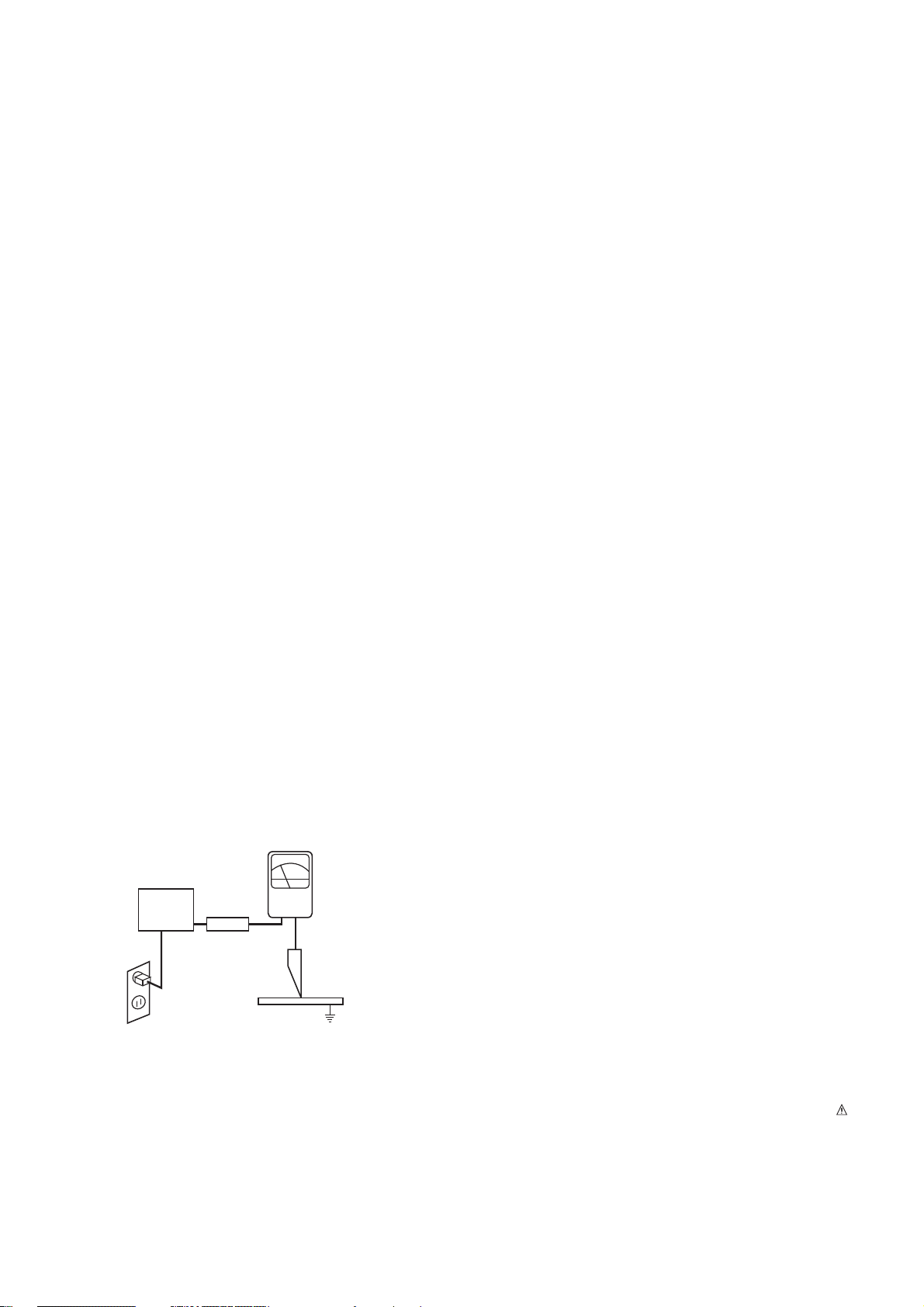
d. Leakage Current Hot Check-With the instrument completely
reassembled, plug the AC line cord directly into a 120 V AC outlet.
(Do not use an isolation transformer during this test.) Use a leakage
current tester or a metering system that complies with American
National Standards Institute (ANSI)
C101.1 Leakage Current for
Appliances and Underwriters Laboratories (UL) 1410, (50.7). With the
instrument AC switch first in the on position and then in the off position,
measure from a known earth ground (metal waterpipe, conduit, etc.) to
all exposed metal parts of the instrument (antennas, handle bracket,
metal cabinet, screwheads, metallic overlays, control shafts, etc.),
especially any exposed metal parts that offer an electrical return path to
the chassis. Any current measured must not exceed 0.5 milliamp.
Reverse the instrument power cord plug in the outlet and repeat the
test.
ANY MEASUREMENTS NOT WITHIN THE LIMITS SPECIFIED HEREIN
INDICATE A POTENTIAL SHOCK HAZARD THAT MUST BE
ELIMINATED BEFORE RETURNING THE INSTRUMENT TO THE
CUSTOMER.
e. X-Radiation and High Voltage Limits-Because the picture tube is the
primary potential source of X-radiation in solid-state TV receivers, it is
specially constructed to prohibit X-radiation emissions. For continued Xradiation protection, the replacement picture tube must be the same
type as the original. Also, because the picture tube shields and mounting
hardware perform an X-radiation protection function, they must be
correctly in place.
High voltage must be measured each time servicing is done that
involves B+, horizontal deflection, or high voltage. Correct operation of
the X-radiation protection circuits also must be reconfirmed each time
they are serviced. (X-radiation protection circuits also may be called
"horizontal disable" or "hold-down.") Read and apply the high voltage
limits and, if the chassis is so equipped, the X-radiation protection circuit
specifications given on instrument labels and in the Product Safety & Xradia
tion Warning note on the service data chassis schematic.
High voltage is maintained within specified limits by close-tolerance
safety-related components/adjustments in the high-voltage circuit.
If high voltage exceeds specified limits, check each component
specified on the chassis schematic and take corrective action.
2. Read and comply with all caution and safety-related notes on or inside
the receiver cabinet, on the receiver chassis, or on the picture tube.
3. Design Alteration Warning- Do not alter or add to the mechanical or
electrical design of this TV receiver. Design alterations and additions,
including, but not limited to, circuit modifications and the addition of
items such as auxiliary audio and/or video output connections, might
alter the safety characteristics of this receiver and create a hazard to
the user. Any design alterations or additions will void the manufacturer's
warranty and will make you, the servicer responsible for personal injury
or property damage resulting therefrom.
4. Picture Tube Implosion Protection Warning-The picture tube in this
receiver employs integral implosion protection. For continued implosion
protection, replace the picture tube only with one of the same type and
number. Do not remove, install, or otherwise handle the picture tube in
any manner without first putting on shatterproof goggles equipped with
side shields. People not so equipped must be kept safely away while
picture tubes are handled. Keep the picture tube away from your body.
Do not handle the picture tube by its neck. Some "in-line" picture tubes
are equipped with a permanently attached deflection yoke; because of
potential hazard, do not try to remove such "permanently attached"
yokes from the picture tube.
5. Hot Chassis Warning-a. Some TV receiver chassis are electrically
connected directly to one conductor of the AC power cord and may be
safely serviced without an isolation transformer only if the AC power
plug is inserted so that the chassis is connected to the ground side of
the AC power source. To confirm that the AC power plug is inserted
correctly, with an AC voltmeter measure between the chassis and a
known earth ground. If a voltage reading in excess of 1.0 V is obtained,
remove and reinsert the AC power plug in the opposite polarity and
again measure the voltage potential between the chassis and a known
earth ground. b. Some TV receiver chassis normally have 85 V AC (RMS)
between chassis and earth ground regardless of the AC plug polarity.
These chassis can be safely serviced only with an isolation transformer
inserted in the power line between the receiver and the AC power
source, for both personnel and test equipment protection. c. Some TV
receiver chassis have a secondary ground system in addition to the main
chassis ground. This secondary ground system is isolated from the AC
power line. The two ground systems are electrically separated by
insulating material that must not be defeated or altered.
6. Observe original lead dress. Take extra care to assure correct lead
dress in the following areas: a. near sharp edges, b. near thermally hot
parts- be sure that leads and components do not touch, c. the AC
supply, d. high voltage, and e.antenna wiring. Always inspect in all areas
for pinched, out-of-place, or frayed wiring. Do not change spacing
between components, and between components and the printed circuit
board. Check the AC power cord for damage.
7. Components, parts, and/or wiring that appear to have overheated or are
otherwise damaged should be replaced with components, parts, or
wiring that meet original specifications. Additionally, determine the
cause of overheating and/or damage and, if necessary, take corrective
action to remove any potential safety hazard.
8. PRODUCT SAFETY NOTICE
Some electrical and mechanical parts have special safety related
characteristics which are often not evident from visual inspection, nor can
the protection they give necessarily be obtained by replacing them with
components rated for higher voltage, wattage, etc. Parts that have
special safety characteristics are identified by shading, by a ¡ ,or by
on schematics and parts lists. Use of a substitute replacement that does
not have the same safety characteristics as the recommended
replacement parts might create shock, fire, and/or other hazards. Product
safety is under review continuously and new instructions are issued
whenever appropriate.
DEVICE
UNDER
TEST
TEST ALL
EXPOSED METAL
SURFACES
2-WIRE CORD
ALSO TEST WITH
PLUG REVERSED
(USING AC ADAPTER
PLUG AS REQUIRED)
EARTH
GROUND
LEAKAGE
CURRENT
TESTER
(READING SHOULD
NOT BE ABOVE
0.5mA)
+ -
AC Leakage Test
1. Application Object
These instructions are applied to SC-023A chassis.
2. Notes
(1) Because this is not a hot chassis, it is not necessary to use
an isolation transformer. However, the use of isolation
transformer will help protect test instrument.
(2) Adjustment must be done in the correct order.
(3) The adjustment must be performed in the circumstance of
25±5°C of temperature and 65±10% of relative humidity if
there is no specific designation.
(4) The input voltage of the receiver must keep
(100~240V)±10%, 50/60Hz in adjusting.
(5) The receiver must be operated for about 15 minutes prior
to the adjustment. But adjusting on the board can be done
in jig state right away.
(6) Signal : The standard color signal is approved in
65±1dBµV.
The standard color signal means digital pattern signal.
(7) If not specified, APC ON is CLEAR.
3. AGC Voltage Adjustment
3.1 Preliminary steps
(1) Input 65dB(±1dB) digital pattern signal into 75Ω antenna
terminal.
(2) Connect digital multimeter to the C102 left terminal(with
Hole/J5) marking with AGC Check.
3.2 Adjustment
(1) Select the SUB 0(RF AGC) mode with a INSTART Key.
(2) Adjust the adjustment data with VOL +, - key until the
digital multimeter voltage show 2.2±0.05V.
(3) CAUTION : Since the signal strength can be easily
changed by the condition of signal cable, you need to
check the signal strength frequently in order to prevent
misadjustment.
4. Screen Voltage Adjustment
4.1 Preliminary steps
(1) Input digital pattern signal into 75Ω terminal.
(2) Set Picture condition to “CLEAR”.
CLEAR CONTRAST : 100
BRIGHTNESS : 50
COLOR : 50
SHARPNESS : 50
TINT : 0
4.2 Adjustment
(1) Press “ADJ” or “SVC” button on the remote control to make
one horizontal line.
(2) Turn the Screen volume not to see one horizontal line and
turn oppositely until it starts to display.
5. Purity and Convergence Adjustment
5.1 Purity Adjustment
(1) Preliminary steps
1. Receive Red Raster Pattern.
2. Degauss CPT and Cabinet with degaussing coil.
(2) Horizontal Line Adjustment
1. Pre-adjust Static Convergence(STC) with 4-pole & 6pole magnet.
2. Check if the beam lands at mask hole by setting two 2Pole magnets in opposite direction repectively.
3. If not, adjust 2-Pole magnet so the beam as to land at
mask hole accurately.
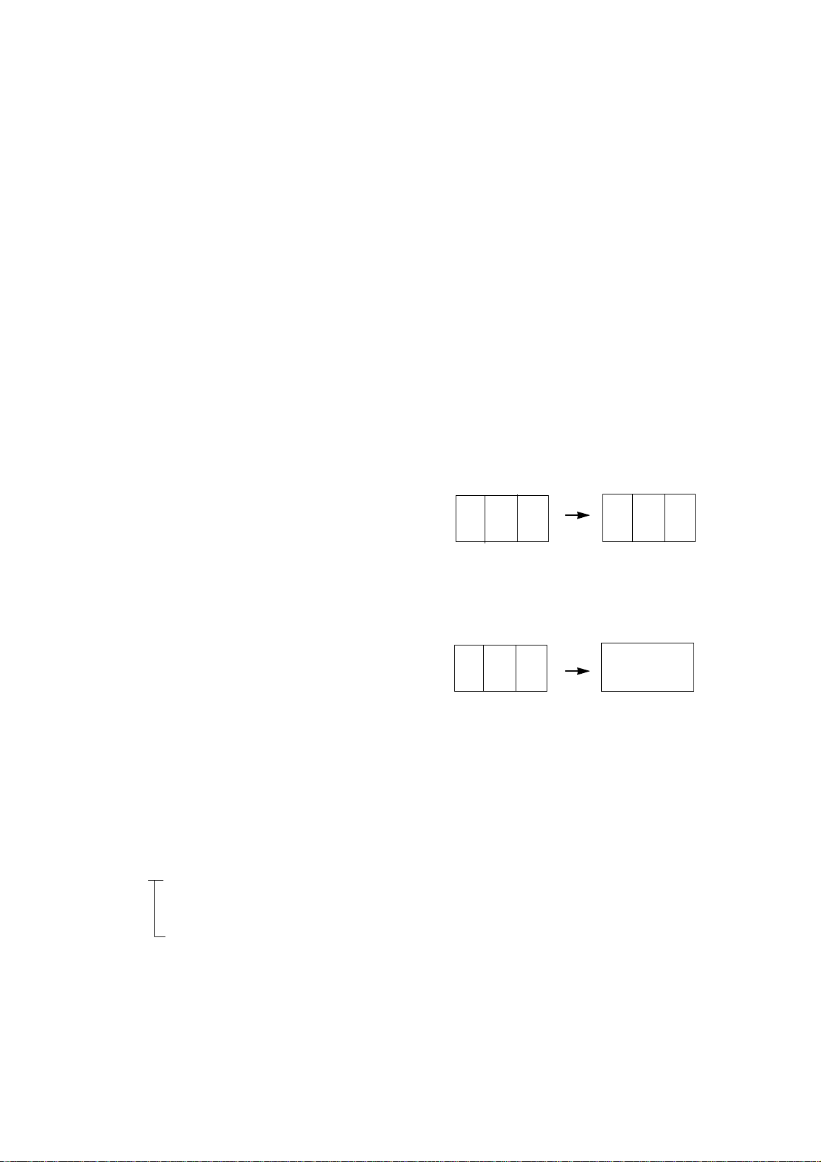
(3) Purity Adjustment
1. Adhere DY closely to CPT.
2. Receive Red Pattern and adjust the 2-Pole magnet so
Red Color Bar as to locate center and make the portion
of Green color and Blue color same. <Fig. 1>
(Be careful of HALO if two 2-Pole magnet are open over
30 degree)
3. Make the full screen Red by pulling DY back slowly.
<Fig. 2>
(When adhering DY, use the electric driver of which
turning force is lower than 10Kg/Cm.)
5.2 Convergence Adjustment
(1) Test equipment
1. Degaussing Coil
2. Convergence fixing jig
(2) Preliminary steps
1. Heat run over 30 minutes before adjustment.
2. Degauss CPT and Cabinet with degaussing coil.
3. Rececive Cross Hatch Pattern.
4. Adjust Contrast and Brightness for easy observation.
(3) Static Convergence (STC) Adjustment
1. Receive Crosshatch Pattern.
2. Adjust Focus with focus volume.
3. Open two 4-Pole magnets until vertical Red and Blue
lines are unified.
4. Rotate the 4-Pole magnets keeping the angle between
two 4-Pole magnets until horizontal Red and Blue lines
are unified.
5. Open two 6-Pole magnets until vertical Red and Green
lines are unified.
- 4 -
ADJUSTMENT INSTRUCTION
G R BG R B
RG R B
<Fig. 1>
<Fig. 2>
6. Rotate the 6-Pole magnets keeping the angle between
two 6-Pole magnets until horizontal Red and Blue lines
are unified.
(4) Dynamic Convergence (DYC) Adjustment
1. Vertical Line Adjustment : Adjust by moving DY right and
left.
2. Horizontal Line Adjustment : Adjust by moving DY up
and down.
6. White Balance Adjustment
6.1 Test Equipment
(1) Automatic White Balance meter(Can generate Low/High
light pattern)
(2) White Balance meter(CRT color Analyzer, CA-100)
(3) SVC Remote control for adjustment
6.2 Preliminary steps
Do screen adjustment first.
6.3 Adjustment
(1) White Balance should be adjusted with the SVC remote
control.
(2) Enter into adjustment mode by “INSTART” button.
(3) Adjust the item with CH
D,E.
(4) Adjust the data with VOL F, G.
(5) Adjustment Procedure
1. Adjust “CONTRAST” and “BRIGHT” so the bright level to
be 35Ft_L.
2. Select G-DRIVE(SUB 7) and adjust Y coordinate in High
Light and select B-DRIVE(SUB 8) and adjust X
coordinate so the color coordinates in High light as to
be the values in Table below.
3. Adjust “CONTRAST” and “BRIGHT” so the bright level to
be 4.5Ft_L.
4. Select G-CUT(SUB 5) and adjust Y coordinate in Low
Light and select B-CUT(SUB 6) and adjust X coordinate
so the color coordinates in Low light as to be the values
in Table below.
5. Repeat 1 ~ 4 until the color coordinates in High and
Low color satisfies the Table.
6. Check the adjusted color coordinates with the white
balance meter.
7. Focus Voltage Adjustment
Adjust after operating the receiver enough.
7.1 Preliminary steps
(1) Receive Digital Pattern.
(2) Set Picture condition to “CLEAR”.
7.2 Adjustment
Adjust center focus with upper Focus volume and adjust
corner focus with lower Focus volume.
Repeatedly adjust focus until getting proper focus.
8. Sub-Brightness Adjustment
Do white balance adjustment first.
8.1 Preliminary steps
(1) Receive Mono Scope.
(2) Set Picture condition to “CLEAR”.
8.2 Adjustment
(1) Select “SUB BRI” mode pressing “ADJ” button on the SVC
Remote control.
(2) Adjust until number “2” almost disappears on Gray Scale
of Mono Scope signal by VOL F, G key.
Adjust 21” FLAT Model until number “3” almost disappears.
9. Sub-Tint Adjustment
This adjustment must be done when the TINT is on.
(1) Receive SMPTE.
(2) Select the TINT adjustment mode(Sub-Tint) with the ADJ
key(or SVC key).
(3) Adjust the up and down cyan color same with VOL F, G
key.
- 5 -
Location
C
L,R,X,Y
A,B,D,E
3,6,9,12
2,4,8,10
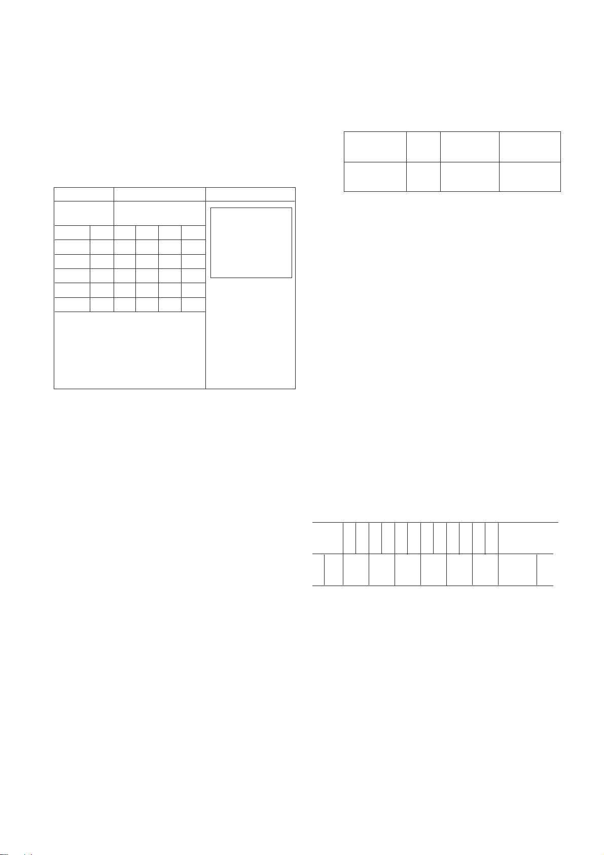
Convergence
Colors : R/B, R/G, B/G <Unit : mm>
* Each indicator stands
for the 30ø circle.
O
Adjust after warming
the Braun tube up for
15 minutes.
O
Adjustment position is
the center of the circle
above.
O
The specification of
horizontal and vertical
direction is equal
10 12 2
A X B
9 L C R 3
D Y E
8 6 4
ConditionSpecificationContent
Colors
Colors
Colors
Colors
Colors
14”
-
0.8
0.8
1.0
1.4
15”
-
0.8
0.8
1.0
1.4
20”
-
0.8
0.8
1.0
1.4
21”
-
0.8
0.8
1.0
1.4
Color
temperature
13,000¡ 800
MPCD
¡ 10
X Coordinate
0.266¡ 0.008
Y Coordinate
0.282¡ 0.008
0 1 2 3 4 5 6 7 8 9
MONO SCOPE
F GRAY SCALE
F COLOR BAR

10. Deflection Data Adjustment
10.1 Preliminary Steps
(1) Set the Deflection data with the SVC Remote control.
(2) Enter into Deflection adjustment mode by “INSTART”
button.
(3) Use “CHD”, “CHE” button for changing adjustment item
(4) Use “VOLF, VOLG” button for Data change.
10.2 Adjustment
(1) Horizontal Position Adjsutment
Select SUB 1(H POSIT) and adjust until left and right
screen are symmetrically equal.
(2) Vertical Position Adjustment
Select SUB 2(V-POS) and adjust until the mechanical
center point and the center of screen unite.
(3) Vertical Size Adjustment
Select SUB 3(V SIZ) and adjust until the smaller inscribed
circle of Digital Pattern coincides with the outer frame of
screen as figure below.
- 6 -
11. IIC BUS Adjustment Data Table
11.1 21
¡¡––
FLAT Model
* Adjustment is necessary from SUB 0 to SUB 8 and the OSD is Blue.
* Adjustment is unnecessary from SUB 9 to SUB 30 and the OSD is Red.
Menu
S - 0
S - 1
S - 2
S - 3
S - 4
S - 5
S - 6
S - 7
S - 8
S - 9
S - 10
S - 11
S - 12
S - 13
S - 14
S - 15
S - 16
S - 17
S - 18
S - 19
S - 20
S - 21
S - 22
S - 23
S - 24
S - 25
S - 26
S - 27
S - 28
S - 29
S - 30
S - 31
Adjustment
AGC Voltage Adj.
Horizontal Postilion
Vertical Position
Vertical SIZE
R CUT OFF
G CUT OFF
B CUT OFF
Inside TEST Pattern
Range
0 ~ 63
0 ~ 31
0 ~ 7
0 ~ 63
0 ~ 255
0 ~ 255
0 ~ 255
0 ~ 127
0 ~ 127
0 ~ 63
0 ~ 15
0 ~ 15
0 ~ 3
0 ~ 3
0 ~ 1
0 ~ 1
0 ~ 3
0 ~ 7
0 ~ 1
0 ~ 1
0 ~ 1
0 ~ 3
0 ~ 3
0 ~ 7
0 ~ 3
0 ~ 1
0 ~ 1
0 ~ 1
0 ~ 1
0 ~ 1
0 ~ 70
OSD
RF AGC
H POSIT
V-POS
V SIZE
R-CUT
G-CUT
B-CUT
G-DRIVE
B-DRIVE
V CENTE
V LINEA
V S COR
AFC GAI
ABL GAI
YPL
C-GAMMA
N MATRI
A-SHARP
RGBMUTE
AU GAIN
MIX GAI
Y-GAMMA
BLK STR
Y DL
ABL POI
BPT-TOF
V AGC
V R BIA
SYN SEP
OVER MOD
OSD POSITION
Initial setting
50
13
3
53
128
128
128
64
64
36
9
7
0
3
1
1
1
3
0
0
0
3
3
1
0
1
0
1
0
0
17
Remark
Necessary
Necessary
Necessary
Necessary
Necessary
Necessary
Necessary
Necessary
Necessary
Unnecessary
Unnecessary
Unnecessary
Unnecessary
Unnecessary
Unnecessary
Unnecessary
Unnecessary
Unnecessary
Unnecessary
Unnecessary
Unnecessary
Unnecessary
Unnecessary
Unnecessary
Unnecessary
Unnecessary
Unnecessary
Unnecessary
Unnecessary
Unnecessary
Unnecessary
Unnecessary
 Loading...